Power Meter User Manual English Only - Quarq
Power Meter User Manual English Only - Quarq
Power Meter User Manual English Only - Quarq

You also want an ePaper? Increase the reach of your titles
YUMPU automatically turns print PDFs into web optimized ePapers that Google loves.
<strong>Power</strong> <strong>Meter</strong> <strong>User</strong> <strong>Manual</strong><br />
95-6118-008-000 Rev A Copyright ©SRAM LLC, 2012
Statement of Compliance for FCC and Industry Canada:<br />
<strong>Quarq</strong> Technology / SRAM LLC.<br />
Model#: 0808<br />
FCC ID: C9O-MERC1<br />
IC: 10161A-MERC1<br />
This equipment has been tested and found to comply with the limits for a Class B digital device, pursuant to<br />
Part 15 of the FCC Rules. These limits are designed to provide reasonable protection against harmful interference<br />
in a residential installation. This equipment generates uses and can radiate radio frequency energy and,<br />
if not installed and used in accordance with the instructions, may cause harmful interference to radio communications.<br />
However, there is no guarantee that interference will not occur in a particular installation.<br />
Operation is subject to the following two conditions:<br />
1 This device may not cause harmful interference, and<br />
2 this device must accept any interference received, including interference that may cause undesired<br />
operation.<br />
<br />
<br />
<br />
were met.<br />
<br />
operate this equipment.<br />
Statement of RoHS Compliance<br />
<br />
<br />
<br />
<br />
<br />
<br />
2
and ®, respectively.<br />
<br />
SRAM LLC WARRANTY<br />
ExTENT of LiMiTEd WARRANTY<br />
<br />
period of two years after original purchase. This warranty only applies to the original owner and is not transferable. Claims under<br />
this warranty must be made through the retailer where the bicycle or the SRAM component was purchased. Original proof of<br />
purchase is required. Except as described herein, SRAM makes no other warranties, guaranties, or representations of<br />
any type (express or implied), and all warranties (including any implied warranties of reasonable care, merchantibility,<br />
<br />
LoCAL LAW<br />
<br />
<br />
<br />
consistent with such law, under such local law, certain disclaimers and limitations of this warranty statement may apply to the<br />
<br />
<br />
a. Preclude the disclaimers and limitations of this warranty statement from limiting the statutory rights of the consumer<br />
<br />
b. Otherwise restrict the ability of a manufacturer to enforce such disclaimers or limitations.<br />
For Australian customers:<br />
<br />
<br />
a claim by contacting SRAM Australia, 6 Marco Court, Rowville 3178, Australia. For valid claims SRAM will, at its option, either<br />
<br />
given by this warranty are additional to other rights and remedies that you may have under laws relating to our products. Our<br />
goods come with guarantees that cannot be excluded under the Australian Consumer Law. You are entitled to a replacement<br />
or refund for a major failure and for compensation for any other reasonably foreseeable loss or damage. You are also entitled<br />
to have the goods repaired or replaced if the goods fail to be of acceptable quality and the failure does not amount to a major<br />
failure.<br />
LiMiTATioNS of LiAbiLiTY<br />
<br />
SRAM or its third party suppliers be liable for direct, indirect, special, incidental, or consequential damages.<br />
3
LiMiTATioNS of WARRANTY<br />
This warranty does not apply to products that have been incorrectly installed and/or adjusted according to the respective SRAM<br />
<br />
This warranty does not apply to damage to the product caused by a crash, impact, abuse of the product, non-compliance with<br />
<br />
beyond its design.<br />
<br />
<br />
chargers.<br />
This warranty does not apply when the serial number or production code has been deliberately altered, defaced or removed.<br />
This warranty does not apply to normal wear and tear. Wear and tear parts are subject to damage as a result of normal use,<br />
failure to service according to SRAM recommendations and/or riding or installation in conditions or applications other than<br />
recommended.<br />
<br />
Dust seals<br />
Bushings<br />
Air sealing o-rings<br />
Glide rings<br />
Rubber moving parts<br />
Foam rings<br />
<br />
main seals<br />
<br />
Stripped threads/bolts (aluminium,<br />
<br />
<br />
Notwithstanding anything else set forth herein, this warranty is limited to one year for all electronic and electronic related<br />
<br />
charger warranty does not include damage from power surges, use of improper charger, improper maintenance, or such other<br />
misuse.<br />
This warranty shall not cover damages caused by the use of parts of different manufacturers.<br />
This warranty shall not cover damages caused by the use of parts that are not compatible, suitable and/or authorised by SRAM<br />
for use with SRAM components.<br />
<br />
Garmin®, Edge®, and Forerunner® are registered copyrights of Garmin Corporation.<br />
4<br />
<br />
Chains<br />
<br />
Cassettes<br />
<br />
Handlebar grips<br />
Shifter grips<br />
<br />
<br />
<br />
Bottomout pads<br />
Bearings<br />
Bearing races<br />
Pawls<br />
Transmission gears<br />
<br />
Free hubs<br />
Aero bar pads<br />
Corrosion<br />
Tools<br />
Motors<br />
Batteries
TABLE OF CONTENTS<br />
POWER METER ANATOMY ................................................................................. 6<br />
INSTALLATION ...................................................................................................... 7<br />
MAGNET INSTALLATION ..............................................................................................................7<br />
BB CUP MOUNT INSTALLATION .............................................................................................. 8<br />
CABLE GUIDE MOUNT INSTALLATION ................................................................................. 9<br />
ADHESIVE PUTTY INSTALLATION .........................................................................................10<br />
CRANK INSTALLATION ...................................................................................... 11<br />
SET UP ................................................................................................................... 11<br />
LED FUNCTIONALITY ...................................................................................................................11<br />
PAIRING .............................................................................................................................................. 12<br />
ZEROING ............................................................................................................................................ 12<br />
CHAINRING INSTALLATION ..............................................................................14<br />
MAINTENANCE AND CARE ................................................................................15<br />
BATTERY INFORMATION ............................................................................................................15<br />
BATTERY CARE ...............................................................................................................................15<br />
CLEANING .........................................................................................................................................15<br />
TROUBLESHOOTING ...........................................................................................16<br />
TABLE OF CONTENTS<br />
5
POWER MET ER A NAT OMY<br />
Crankarm Spider Serial Number<br />
/ ANT+ ID<br />
Battery Compartment<br />
6 POWER METER ANATOMY<br />
LED<br />
Cadence Sensor Ring<br />
Cadence Sensor Ring Label
I NST ALLATION<br />
MAGNET INSTALLATI ON<br />
The included magnet must be installed for the power meter to function. There are three ways to install<br />
the magnet: BB Cup Mount, Cable Guide Mount, and Adhesive Putty. Please choose the one mounting<br />
<br />
When properly installed, the magnet should be in line with the cadence sensors and within 2-8 mm of the<br />
sensor ring<br />
allow the magnet to contact the power meter.<br />
It is easier to install the magnet when the cranks are not installed on the frame.<br />
BB Cup Mount Cable Guide Mount Adhesive Putty<br />
INSTALLATION<br />
7
BB CUP MOUNT INSTALLATI ON<br />
The BB Cup Mount is only compatible with threaded bottom brackets. It does not work with frames that<br />
have bearings pressed into the bottom bracket (BB30, PF30, etc.). Frames using threaded bottom bracket<br />
adapters (ie. SRAM GXP30 BB Adapter) may use the BB Cup Mount if the mount is installed onto the<br />
threaded drive side bottom bracket cup.<br />
1. <br />
2. Slide the BB Cup Mount over the threads of the drive side bearing cup with the magnet facing away<br />
from the frame.<br />
3. <br />
recommended torque.<br />
<br />
8 BB CUP MOUNT INSTALLATION<br />
2-8 mm<br />
(1/16”-3/8”)
CAB LE G U I DE MOUNT INSTALLATI ON<br />
The Cable Guide Mount should only be used when the cable guide is fastened with a screw. If the cable<br />
guide is fastened with a rivet, use the Bottom Bracket Cup Mount or Adhesive Putty instead.<br />
Installation Notes: Do not allow the magnet to contact the power meter. When properly installed, the<br />
<br />
1. <br />
2. Loosen the cable guide screw. It may be helpful to shift the front derailleur to the small chainring<br />
<br />
easier to slide the cable guide mount under the cable guide.<br />
3. Slide the mount under the cable guide. The guide can be installed with the magnet pointed down (as<br />
<br />
<br />
5. Tighten the cable guide screw.<br />
6. <br />
2-8 mm<br />
(1/16”-3/8”)<br />
CABLE GUIDE MOUNT INSTALLATION<br />
9
A DHESI VE P UTTY INSTALLATI ON<br />
The included adhesive putty will permanently attach the magnet to your frame. Other non-permanent<br />
attachment options include: hot glue, some epoxies, electrical tape, or similar adhesives.<br />
Installation Notes: Do not allow the magnet to contact the power meter. When properly installed, the<br />
<br />
<br />
1. <br />
2. <br />
<br />
<br />
3. Clean the frame with the included alcohol pad prior to attaching the magnet.<br />
<br />
5. <br />
the frame.<br />
6. <br />
minutes, and will cure in 1 hour.<br />
7. <br />
8. <br />
10 ADHESIVE PUTTY INSTALLATION<br />
0<br />
1 2<br />
3 4 5 6 7 8 9 1 2 3 4<br />
10<br />
20 30 40<br />
mm/inch<br />
OFF ON ZERO<br />
1 2 3 4 5 6<br />
7<br />
100 120<br />
8 9 1 2<br />
5<br />
130
CRANK INST ALLATION<br />
<br />
instructions.<br />
<br />
components. Please contact <strong>Quarq</strong> customer service with any frame compatibility questions. An updated<br />
list of compatible frames is available at <strong>Quarq</strong>.com.<br />
SET UP<br />
LED FUNC T I ONALI TY<br />
<br />
in the Troubleshooting section for more LED information.<br />
<br />
twice when battery is inserted<br />
<br />
<br />
once when entering the sleep state<br />
LED<br />
CRANK INSTALLATION<br />
11
P A I R I NG<br />
Before pairing your power meter to a computer, make sure you are at least 10 meters (30 feet) from any<br />
other ANT+ device. This will keep you from accidentally pairing to another person’s ANT+ device.<br />
To pair the power meter<br />
meter and begin broadcasting ANT+ messages. The power meter will shut off after about 10 minutes of<br />
inactivity.<br />
<br />
G ARMIN® E DGE® 800<br />
To pair the power meter:<br />
Click the <strong>Power</strong> button tap the Dumbbell icon Rescan<br />
“<strong>Power</strong> <strong>Meter</strong> Detected”<br />
G ARMIN E DGE 500<br />
To pair the power meter:<br />
Menu Settings Bike Settings Bike 1 ANT+<strong>Power</strong> Rescan<br />
“<strong>Power</strong> <strong>Meter</strong> Detected”<br />
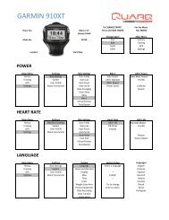
G ARMIN FORERUNNER® 310XT & 910XT WATC H<br />
Your watch must be in bike mode in order to pair and zero your power meter (press and hold the Mode<br />
button).<br />
To pair the power meter:<br />
Mode Bike Settings Bike 1 Ant+<strong>Power</strong> Restart Scan<br />
“<strong>Power</strong> <strong>Meter</strong> Detected” will appear on your screen when the units are paired.<br />
ZEROI NG<br />
<br />
Auto Zero and <strong>Manual</strong> Zero.<br />
When to perform the Zero procedure<br />
For best results, you should perform the <strong>Manual</strong> Zero procedure before you start each ride. The Auto<br />
Zero procedure can be performed instead of a <strong>Manual</strong> Zero or if your computer cannot send a “Calibrate”<br />
command; if the temperature changes greatly during your ride; or if you feel that you are getting inaccurate<br />
data.<br />
12 PAIRING
<strong>Manual</strong> Zero<br />
The <strong>Manual</strong> Zero procedure should be performed before every ride with the rider off the bike and with the<br />
drive-side crank arm at 6 o’clock.<br />
<br />
<br />
<br />
is typically between +/- 1000<br />
<br />
<br />
or if day-to-day values vary widely, please call <strong>Quarq</strong> customer service.<br />
When performing the <strong>Manual</strong> Zero<br />
<br />
ANT+ computer to send the “Calibrate” command. ash<br />
G ARMIN® E DGE® 800<br />
Click the <strong>Power</strong> button tap the Dumbbell icon Calibrate<br />
G ARMIN E DGE 500<br />
Menu Settings Bike Settings Bike 1 ANT+<strong>Power</strong> Calibrate<br />
G ARMIN FORERUNNER® 310XT & 910XT WATC H<br />
Mode Bike Settings Bike 1 Ant+<strong>Power</strong> Calibrate<br />
Auto Zero<br />
<br />
is complete. Auto Zero procedure may be<br />
<br />
<br />
Zero Offset Stabilization<br />
<br />
this time you should perform the procedure regularly to ensure accurate power readings.<br />
<br />
ZEROING<br />
13
CHA I NRI N G INST ALLATION<br />
If you are replacing worn rings with a new pair of the same model, or replacing with SRAM Red TT<br />
chainrings, re-calibration is not required.<br />
<br />
<br />
Tighten SRAM steel chainring<br />
<br />
Hidden bolt crank<br />
5<br />
Non-hidden bolt crank<br />
6<br />
6 5<br />
14 CHAINRING INSTALLATION<br />
Knurled Edge<br />
Chainring bolt<br />
5
MAI N T ENANC E AND CARE<br />
BATTERY INF ORM ATI ON<br />
The power meter is powered by a CR2032 coin cell battery.<br />
The battery can be replaced without any special tools. To replace the<br />
<br />
it open. The battery should be installed with the “+” facing out. Reinstall<br />
and hand tighten the battery cover after the battery is replaced.<br />
<br />
<br />
operating conditions the battery will last for about 300 hours of riding.<br />
The power meter will send a warning when the battery is low. However,<br />
not all ANT+ computers will display the message.<br />
The power meter retains its sensor ID throughout battery changes and<br />
will remain properly paired with your computer.<br />
BATTERY C ARE<br />
<br />
free of corrosion and<br />
moisture.<br />
CLEANI NG<br />
<br />
<br />
and chainrings with clean or soapy water, then rinse with clean water and let air dry. Do not use harsh<br />
chemicals and do not use a high-pressure washer.<br />
MAINTENANCE AND CARE<br />
15
T ROU BLESH OOTIN G<br />
<br />
<br />
<br />
<br />
<br />
<br />
<br />
<strong>Power</strong> <strong>Meter</strong> does not pair with the computer<br />
<br />
sure the battery contact is free of corrosion.<br />
The magnet<br />
should be installed according to the instructions on pages 8-10. Once the cadence sensors have been<br />
activated, the power meter will begin transmitting messages and is ready to be paired.<br />
<br />
<br />
If you are using a Garmin ® heart rate enabled, calibration will often be faster<br />
when you are wearing the heart rate monitor/strap. Turn off the ANT+ HRM function if you are not using<br />
a heart rate strap.<br />
<br />
<br />
G ARMIN E DGE® 800<br />
Menu Settings About Edge<br />
G ARMIN E DGE 500<br />
Menu Settings About Edge<br />
To view the menu, you must press and hold the Menu button until the menu pops up.<br />
G ARMIN FORERUNNER® 310XT & 910XT WATC H<br />
Mode Settings About Forerunner<br />
16 TROUBLESHOOTING
Cadence, but no power<br />
<br />
8-10. 12-13.<br />
Remove any separate cadence or speed sensors.<br />
Unusually high or low power values<br />
1. 13.<br />
2. 1000<br />
3. differ by more than 50 points, it may be necessary<br />
to contact Customer Support. Keeping a record of the Zero Offset values will be helpful when<br />
contacting Customer Support.<br />
Remove third party cadence sensors. The power meter delivers both power and cadence data to the<br />
<br />
Inspect and clean the chainrings and power meter, including the chainring mounting tabs. Re-assemble<br />
according to the instructions on page .<br />
<strong>Manual</strong> Zero (Calibration) Fails<br />
<br />
<br />
If you are using a Garmin ® heart rate enabled, calibration will often be faster<br />
when you are wearing the heart rate monitor/strap. Turn off the ANT+ HRM function if you are not using<br />
a heart rate strap.<br />
Wireless Signal Disconnections<br />
<br />
according to the instructions on pages 8-10.<br />
<br />
power meter<br />
<br />
TROUBLESHOOTING<br />
17
WORLD HEADQUARTERS<br />
SRAM LLC<br />
<br />
<br />
QUARQ<br />
3100 1st Ave.<br />
<br />
<br />
ASIAN HEADQUARTERS<br />
SRAM Taiwan<br />
No. 1598-8 Chung Shan Road<br />
<br />
<br />
EUROPEAN HEADQUARTERS<br />
SRAM Europe<br />
<br />
<br />
The Netherlands<br />
www.sram.com © SRAM LLC 2012