Ohio Exposed Wall Mounted Thermostatic Shower - Jacuzzi
Ohio Exposed Wall Mounted Thermostatic Shower - Jacuzzi
Ohio Exposed Wall Mounted Thermostatic Shower - Jacuzzi

You also want an ePaper? Increase the reach of your titles
YUMPU automatically turns print PDFs into web optimized ePapers that Google loves.
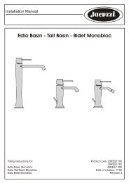
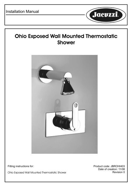
Installation Manual<br />
<strong>Ohio</strong> <strong>Exposed</strong> <strong>Wall</strong> <strong>Mounted</strong> <strong>Thermostatic</strong><br />
<strong>Shower</strong><br />
Fitting instructions for:<br />
<strong>Ohio</strong> <strong>Exposed</strong> <strong>Wall</strong> <strong>Mounted</strong> <strong>Thermostatic</strong> <strong>Shower</strong><br />
Product code: JBROHI403<br />
Date of creation: 11/08<br />
Revision 0
Installation Manual<br />
Water Regulations Requirements :<br />
It is important to ensure that the water supplies to your taps and mixers are connected in<br />
accordance with the water regulation (WRAS) requirements and good plumbing practice.<br />
It is good plumbing practice that the supplies of hot and cold water to the Bathroom fitting should<br />
be equal (balanced) pressure in order to provide a consistent flow. Supplies should be from a<br />
common source, either mains or tank fed. If supplies are not equal pressures then a Non Return<br />
Valve ( Check Valve ) should be fitted on the hot inlet.<br />
It is our recommendation and good plumbing practice that a service valve should be installed in the<br />
inlet supply lines to allow isolation of the Bathroom fitting.<br />
1. Make sure both Hot and Cold supplies have been isolated and drained.<br />
2. Rotate the spout and body so the tap is facing forwards. The spout screw on the tap indicates<br />
the rear of the body. Typically the hot water should be on the left-hand side of the tap.<br />
Before proceeding the assmbly and installation, prepare a smooth surface where you can lay all the<br />
particulars being sure not to damage them.<br />
SYSTEM REQUIREMENTS<br />
To ensure the optimum performance and customer satisfaction please adhere to the following:<br />
• Flush out all pipe work prior to installation.<br />
• Minimum flow pressure for satisfactory operation: (Hot and Cold) 0.2 Bar 20kPa<br />
• Maximum static water pressure 10 Bar 1,000kPa<br />
• If the water pressure exceeds or is likely to exceed 10 Bar 1,000kPa, an approved pressure<br />
limiting valve must be fitted.<br />
• Maximum hot water temperature 80ºC<br />
• If the water temperature exceeds 80ºC an approved tempering valve must be fitted.<br />
• Installation should comply with relevant local authority requirements.<br />
Failure to comply with the above will void all warranties.<br />
Tools required.
Installation Instructions<br />
Please note these instructions are for the hot and cold inlet pipes to enter the mixer from below the<br />
mixer and the outlet to the shower at the top.<br />
If the inlet pipes are located above the mixer rotate the mixer 180 degrees and fasten as indicated<br />
below.<br />
To ensure correct operation of the valve the installer will need to remove the chrome cover sleeve from<br />
the mixer by unscrewing the two grub screws holding the sleeve in place and undoing the large brass<br />
nut holding the thermo cartridge in place, remove the cartridge and rotate the cartridge 180 degrees and<br />
re-install, ensuring a water tight seal is maintained. Re-position the cover sleeve with the temperature<br />
indication mark facing upwards and then retighten the grub screws to fasten the cover sleeve to the<br />
thermomixer body.<br />
1) Fit plug (not supplied) to shut off bottom outlet<br />
2) Position the thermostatic mixer against a mounting board within a maximum (100mm) and a<br />
minimum (70mm) depth allowed from the back of the mixer and the face of the wall lining and fix.<br />
3) Connect the hot and cold water supplies to the mixer, matching the ot and cold inlet pipes to the<br />
correct hot and cold inlets on the thermo mixer.<br />
4) Connect the pipe work and the volume control valve to the top outlet of the thermostatic mixer, and<br />
the shower rose-slide shower set pipe work to the outlet of the volume control valve.<br />
5) Pressure test by plugging outlet pipes: turn on the water supply and the volume control valve. Once<br />
all joints are proved pressure tight turn off the volume control valve and break the seal on the temporary<br />
outlet plug.<br />
6) Cut an access hole 140mm x 70mm in the wall lining for the mixer; fit wall lining.<br />
7) Apply a thin bead of silicone sealant to the back of the faceplate ensuring a continuous seal is<br />
maintained around the edge of the faceplate.<br />
8) Slide the faceplate over the mixer ensuring the faceplate is correctly positioned on the wall and<br />
covering the access hole.<br />
To fit the handle:<br />
Please note the thermostatic valve has been factory set at approximately 38° C when the handle is<br />
positioned on the mixer at the safety button position. (This will be dependant on the hot and cold water<br />
inlet temperatures).<br />
1) Fit the handle to the valve with the blade of the handle facing in a downward (6 o clock) position and<br />
ensuring the lug on the underside of the handle is just touching the safety button stop on the mixer.<br />
2) Turn on the water supply and test the temperature being delivered from the thermostatic mixer.<br />
To increase the temperature being delivered at the safety button position, remove the handle and turn<br />
the spindle of the thermostatic mixer anticlockwise a few degrees and retest the temperature.<br />
Likewise to decrease the temperature turn the spindle clockwise a few degrees and retest te<br />
temperature.<br />
When the appropriate temperature has been achieved align the handle with the handle facing in a<br />
downward (6 o clock) position and ensuring the lug on the underside of the handle is just touching the<br />
safety button stop on the mixer, tighten the grub screw under the handle.
Installation Manual<br />
Care and Maintenance<br />
Important: When joining any screw connections always use PTFE tape and ensure the joints are<br />
fully tightened. Once the product is installed always check the entire installation for leaks.<br />
Your product may require non-return valves to suit your water system or to conform to local water<br />
Bylaws.<br />
Once the product has been installed turn both the hot and cold water on, thoroughly flush any small<br />
particles that may have been dislodged during the installation of the product.<br />
Only clean the product with a soft cloth, warm water and a mild detergent solution, rinse the product<br />
clean thoroughly afterwards with water. Do not use any abrasive or harsh chemical products,<br />
otherwise this will invalidate your guarantee.<br />
These instructions are only intended as a guide, if there is any doubt then<br />
contact a certified plumber.<br />
Please ensure you register your product with <strong>Jacuzzi</strong> UK using the Warranty<br />
Card enclosed in this box.<br />
<strong>Jacuzzi</strong> UK<br />
For further information please contact:<br />
Customer service<br />
<strong>Jacuzzi</strong> UK<br />
Woodlands, Roydsdale Way<br />
Euroway Trading Estate<br />
Bradford, West Yorkshire<br />
Telephone: 01274 475 178<br />
Fax: 01274 654 771<br />
e-mail: aftersales@jacuzziuk.com<br />
www.jacuzzi.co.uk