
Create successful ePaper yourself
Turn your PDF publications into a flip-book with our unique Google optimized e-Paper software.
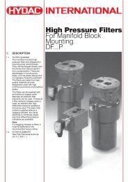
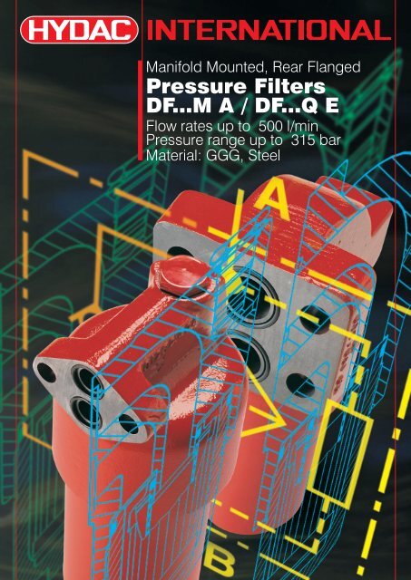
Manifold Mounted, Rear Flanged<br />
<strong>Pressure</strong> <strong>Filters</strong><br />
DF...M A / DF...Q E<br />
Flow rates up to 500 l/min<br />
<strong>Pressure</strong> range up to 315 bar<br />
Material: GGG, Steel
1. DESCRIPTION<br />
1.1. FILTER HOUSING<br />
Construction<br />
The filter housings have been<br />
designed in accordance with<br />
international regulations. They<br />
consist of a filter head and a screwin<br />
filter bowl.<br />
Standard specification:<br />
l Mounting holes in the head<br />
l 2-piece bowl for size 990 and<br />
above<br />
l Suitable for HFA/HFC fluids<br />
l Oil drain plug with automatic<br />
pressure relief (for size 330 and<br />
above)<br />
Interface<br />
l DF 60-280 M A:<br />
Outlet above inlet<br />
l DF 30-280 Q E:<br />
Inlet above outlet<br />
option (size 160, 240, 280):<br />
Outlet above inlet (…/-OAI)<br />
l DF 330-1320 Q E:<br />
Outlet above inlet<br />
1.2. FILTER ELEMENTS<br />
Hydac filter elements fulfil all ISO<br />
test criteria.<br />
l ISO 3724 Verification of flow<br />
fatigue characteristics<br />
l ISO 4572 Contamination<br />
retention capacity<br />
l ISO 4572 Multi-pass method for<br />
evaluating filtration performance<br />
l ISO 3968 Evaluation of pressure<br />
drop versus flow characteristics<br />
l ISO 2942 Bubble Point Test<br />
l ISO 2941 Verification of collapse/<br />
burst resistance<br />
Reliable filter operation is only<br />
guaranteed with original<br />
HYDAC filter elements.<br />
The filter elements are also<br />
suitable for use in dynamic<br />
applications due to their high<br />
pressure stability; max. permiss.<br />
Dp across the element:<br />
Betamicron â (BH3HC) : 210 bar<br />
Betamicron â (BN3HC) : 25 bar<br />
Wire mesh (W/HC) : 30 bar<br />
Stainless steel<br />
fibre (V) : 210 bar<br />
Fluid compatibility<br />
All filter materials are suitable for<br />
mineral oils, lubrication oils, nonflam,<br />
synthetic and rapidly<br />
biodegradable oils. For use with<br />
water, please contact our sales/<br />
technical department.<br />
For further details on filter<br />
elements, please see point 3.2.<br />
and brochure no.: E 7.200../..<br />
2
1.3. CLOGGING INDICATORS<br />
Type of indicator<br />
VD differential pressure indicator up to 450 bar operating pressure<br />
VM differential pressure indicator up to 210 bar operating pressure<br />
<strong>Pressure</strong> setting<br />
5 standard (others on request)<br />
Indicator type code (options)<br />
B. = visual<br />
C. = electrical<br />
D. = visual/electrical<br />
Modification number<br />
0 the latest version is always supplied<br />
Supplementary details<br />
-V Viton<br />
-LED 2 light-emitting diodes up to 24 volt<br />
-L.. light with corresponding voltage (24, 48, 110, 220 volt)<br />
-W only for oil-water emulsions HFA, HFC (only possible for version "VD")<br />
For further details on clogging indicators, please see:<br />
brochure no.: E 7.050../..<br />
1.4. SEALS<br />
Choice of Perbunan (= NBR).<br />
1.5. SPECIAL MODELS AND<br />
ACCESSORIES<br />
– with bypass valve<br />
– oil drain plug up to size 280<br />
– seals in FPM, EPDM<br />
– test and inspection certificates<br />
1.6. SPARE PARTS<br />
See Original Spare Parts List and<br />
Maintenance Instructions, no.: E<br />
7.555.E../..<br />
VD 5 D . 0 /-L220<br />
2. GENERAL<br />
Mounting<br />
Manifold mounted rear flanged<br />
Temperature range<br />
-10 °C to +100 °C<br />
(-30 °C to -10 °C only pmax 2<br />
is permissible)<br />
<strong>Pressure</strong> setting of the<br />
clogging indicator<br />
Dp a = 5 bar -0.5 bar<br />
Other pressure settings on<br />
request<br />
Cracking pressure of<br />
bypass valve<br />
Dp O = 6 bar +0.6 bar<br />
Other pressure settings on<br />
request<br />
Circuit diagram<br />
differential pressure<br />
indicator<br />
3
3. MODEL CODE<br />
(also order example)<br />
3.1. COMPLETE FILTER<br />
Filter type<br />
Filter material<br />
BN/HC Betamicron â (BN3HC)<br />
BH/HC Betamicron â (BH3HC)<br />
W/HC Stainless steel wire mesh<br />
V Stainless steel fibre<br />
Size: filter and element<br />
M A: 60, 110, 140, 160, 240, 280<br />
Q E: 30, 60, 110, 140, 160, 240, 280,<br />
330, 500, 660, 990, 1320<br />
Operating pressure<br />
M: 250 bar<br />
Q: 315 bar<br />
Type of connection / Connection size<br />
A: 2 mounting holes<br />
E: 4 mounting holes<br />
Filtration rating in µm<br />
BN3HC, BH3HC, V : 3, 5, 10, 20<br />
W/HC : 25, 50, 100, 200<br />
Type of clogging indicator<br />
Y with plastic blanking plug<br />
A with steel blanking plug for other clogging indicators,<br />
B with visual indicator see brochure no. E 7.050../..<br />
C with electrical indicator<br />
D with combined visual/electrical indicator<br />
Type code<br />
1 1 version with 1-piece bowl: up to size 660<br />
2 2 version with 2-piece bowl: size 660-1320<br />
Modification number<br />
X the latest version is always supplied<br />
Supplementary details<br />
V FPM seals, filter suitable for rapidly biodegradable oils and phosphate ester (HFD-R)<br />
W suitable for oil-water emulsions HFA, HFC<br />
(only necessary when using a clogging indicator and/or V or W/HC elements)<br />
L...<br />
LED<br />
light with corresponding voltage (24V, 48V, 110V, 220V)<br />
2 light-emitting diodes up to 24 volt<br />
ù only on clogging<br />
û type D<br />
B. special cracking pressure of bypass (B3 = 3 bar, B6 = 6 bar)<br />
SO184 pressure release / oil drain plug (up to size 280)<br />
OAI outlet above inlet (only for DF 160, 240, 280 Q E)<br />
SO348 for operating pressure p £ 210 bar (see point 4.)<br />
max<br />
DF BN/HC 60 Q E 10 D 1 . X /-V-L24<br />
4
3.2. REPLACEMENT ELEMENT<br />
Size<br />
0030, 0060, 0110, 0140, 0160, 0240<br />
0280, 0330, 0500, 0660, 0990, 1320<br />
Type<br />
D<br />
Filtration rating in µm<br />
BN3HC, BH3HC, V : 3, 5, 10, 20<br />
W/HC : 25, 50, 100, 200<br />
Filter material<br />
BN3HC, BH3HC, V, W/HC<br />
Supplementary details<br />
V = FPM seals, filter suitable for rapidly biodegradable oils<br />
and phosphate ester (HFD-R)<br />
W = element suitable for oil-water emulsions HFA, HFC<br />
(only necessary for V and W/HC elements)<br />
4. FILTER SPECIFICATIONS<br />
Version M A Q E<br />
p max 250 bar 315 bar<br />
Temperature range -30 °C to 100 °C (see point 2)<br />
<strong>Pressure</strong> setting of 5 bar<br />
the clogging indicator (Standard)<br />
Type of Standard: VD<br />
clogging indicator For SO348: VM<br />
Material of filter head GGG 40<br />
Material of filter bowl steel<br />
Cracking pressure of bypass 6 bar<br />
Sizes 60-280 30-1320<br />
0330 D 010 BN3HC /-V<br />
5
5. FILTER CALCULATION/SIZING<br />
The total pressure drop of a filter at a certain flow rate is<br />
the sum of the housing Dp and the element Dp.<br />
The pressure drop can either be determined with the aid<br />
of our FSP Filter Sizing Program, which is available free<br />
of charge, or by using the following graphs.<br />
5.1. DP-Q HOUSING GRAPHS TO ISO 3968<br />
The housing graphs apply to mineral oil with a density<br />
of 0.86 kg/dm3 and a viscosity of 30 mm²/s. In this case,<br />
the differential pressure changes proportionally to the<br />
density.<br />
Dp in bar<br />
Dp in bar<br />
Dp in bar<br />
DF 60/110/140 M A<br />
DF 160/240/280 M A<br />
DF 30 Q E<br />
Q in l/min<br />
Q in l/min<br />
Q in l/min<br />
Dp in bar<br />
Dp in bar<br />
Dp in bar<br />
DF 60/110/140 Q E<br />
Q in l/min<br />
DF 160/240/280 Q E (also /-OAI)<br />
Q in l/min<br />
DF 330/500/660/990/1320 Q E<br />
Q in l/min<br />
6
5.2. DP-Q GRAPHS - FILTER ELEMENTS<br />
The element graphs apply to mineral oil with a<br />
kinematic viscosity of 30 mm²/s. The pressure drop<br />
changes proportionally to the change in viscosity<br />
(see Example 5.3.).<br />
Dp in bar<br />
Dp in bar<br />
Dp in bar<br />
2<br />
2<br />
1.8 1,8 1.8<br />
1.6 1,6<br />
1.6<br />
1.4 1,4 1.4<br />
1.2 1,2<br />
1.2<br />
1<br />
1<br />
0.8 0,8<br />
0.8<br />
0.6 0,6<br />
0.6<br />
0.4 0,4<br />
0.4<br />
0.2 0,2<br />
0.2<br />
0<br />
2<br />
1.8 1,8<br />
1.6 1,6<br />
1.4 1,4<br />
1.2 1,2<br />
1<br />
0.8 0,8<br />
0.6 0,6<br />
0.4 0,4<br />
0.2 0,2<br />
0<br />
2<br />
1.8 1,8<br />
1.6 1,6<br />
1.4 1,4<br />
1.2 1,2<br />
1<br />
0.8 0,8<br />
0.6 0,6<br />
0.4 0,4<br />
0.2 0,2<br />
0<br />
BN3HC<br />
Size 30<br />
3µm<br />
1 2 3 4 5 6 7<br />
flow rate in l/min<br />
BN3HC<br />
Size 60<br />
Size 110<br />
Size 140<br />
0 15 30 45 60<br />
flow rate in l/min<br />
75 90 105 120<br />
BN3HC<br />
Size 160<br />
Size 240<br />
Size 280<br />
0 50 100 150 200 250<br />
flow rate in l/min<br />
5µm<br />
3µm 5µm<br />
3µm<br />
3µm<br />
10µm<br />
20µm<br />
3µm<br />
10µm<br />
3µm<br />
5µm<br />
20µm<br />
10µm<br />
5µm<br />
20µm<br />
10µm<br />
20µm<br />
5µm<br />
5µm<br />
3µm<br />
10µm<br />
10µm<br />
20µm<br />
20µm<br />
5µm<br />
10µm<br />
20µm<br />
Dp in bar<br />
Dp in bar<br />
Dp in bar<br />
Dp in bar<br />
2<br />
1,8 1.8<br />
1,6 1.6<br />
1,4 1.4<br />
1,2 1.2<br />
1<br />
0,8 0.8<br />
0,6 0.6<br />
0,4 0.4<br />
0,2 0.2<br />
0<br />
1<br />
0.9 0,9<br />
0.8 0,8<br />
0.7 0,7<br />
0.6 0,6<br />
0.5 0,5<br />
0.4 0,4<br />
0.3 0,3<br />
0.2 0,2<br />
0.1 0,1<br />
0<br />
2<br />
1,8 1.8<br />
1,6 1.6<br />
1,4 1.4<br />
1,2 1.2<br />
1<br />
0,8 0.8<br />
0,6 0.6<br />
0,4 0.4<br />
0,2 0.2<br />
0<br />
2<br />
1,8 1.8<br />
1,6 1.6<br />
1,4 1.4<br />
1,2 1.2<br />
1<br />
0,8 0.8<br />
0,6 0.6<br />
0,4 0.4<br />
0,2 0.2<br />
0<br />
BN3HC<br />
Size 330<br />
Size 500<br />
Size 660<br />
0 100 200 300 400 500<br />
BN3HC<br />
Size 990<br />
Size 1320<br />
flow rate in l/min<br />
0 100 200 300 400 500<br />
flow rate in l/min<br />
BH3HC<br />
Size 30<br />
0 10 20 30<br />
flow rate in l/min<br />
40 50 60<br />
BH3HC<br />
Size 60<br />
Size 110<br />
Size 140<br />
3µm<br />
3µm<br />
3µm<br />
5µm<br />
3µm<br />
10µm<br />
3µm<br />
20µm<br />
5µm<br />
5µm<br />
10µm<br />
20µm<br />
10µm<br />
20µm<br />
0 15 30 45 60<br />
flow rate in l/min<br />
75 90 105 120<br />
5µm<br />
5µm<br />
3µm<br />
3µm 10µm<br />
3µm<br />
3µm<br />
5µm<br />
5µm<br />
10µm<br />
20µm<br />
10µm<br />
20µm<br />
10µm<br />
20µm<br />
20µm<br />
5µm<br />
5µm<br />
10µm<br />
10µm<br />
20µm<br />
20µm<br />
7
Dp in bar<br />
Dp in bar<br />
Dp in bar<br />
Dp in bar<br />
2<br />
1,8 1.8<br />
1,6 1.6<br />
1,4 1.4<br />
1,2 1.2<br />
1<br />
0,8 0.8<br />
0,6 0.6<br />
0,4 0.4<br />
0,2 0.2<br />
0<br />
2<br />
1,8 1.8<br />
1,6 1.6<br />
1,4 1.4<br />
1,2 1.2<br />
1<br />
0,8 0.8<br />
0,6 0.6<br />
0,4 0.4<br />
0,2 0.2<br />
0<br />
1<br />
0.9 0,9<br />
0.8 0,8<br />
0.7 0,7<br />
0.6 0,6<br />
0.5 0,5<br />
0.4 0,4<br />
0.3 0,3<br />
0.2 0,2<br />
0.1 0,1<br />
0<br />
1,2 1.2<br />
1<br />
0,8 0.8<br />
0,6 0.6<br />
0,4 0.4<br />
0,2 0.2<br />
0<br />
BH3HC<br />
0 50 100 150 200 250<br />
BH3HC<br />
flow rate in l/min<br />
0 100 200 300 400 500<br />
flow rate in l/min<br />
BH3HC<br />
0 100 200 300 400 500<br />
flow rate in l/min<br />
V<br />
Size 160<br />
Size 240<br />
Size 280<br />
Size 330<br />
Size 500<br />
Size 660<br />
Size 990<br />
Size 1320<br />
Size 30<br />
3µm<br />
flow rate in l/min<br />
3µm<br />
5µm 3µm<br />
0 10 20 30 40 50 60<br />
5µm<br />
10µm<br />
5µm<br />
3µm<br />
20µm<br />
10µm<br />
20µm<br />
5µm<br />
10µm<br />
20µm<br />
3µm<br />
10µm<br />
3µm<br />
5µm<br />
20µm<br />
5µm<br />
10µm<br />
20µm<br />
10µm<br />
20µm<br />
3µm<br />
3µm<br />
5µm<br />
5µm<br />
10µm<br />
20µm<br />
10µm<br />
20µm<br />
3µm<br />
5µm<br />
10µm<br />
20µm<br />
Dp in bar<br />
Dp in bar<br />
Dp in bar<br />
Dp in bar<br />
1,6 1.6<br />
1,4 1.4<br />
1,2 1.2<br />
1<br />
0,8 0.8<br />
0,6 0.6<br />
0,4 0.4<br />
0,2 0.2<br />
0<br />
1<br />
0.9 0,9<br />
0.8 0,8<br />
0.7 0,7<br />
0.6 0,6<br />
0.5 0,5<br />
0.4 0,4<br />
0.3 0,3<br />
0.2 0,2<br />
0.1 0,1<br />
0<br />
1<br />
0,9 0.9<br />
0,8 0.8<br />
0,7 0.7<br />
0,6 0.6<br />
0,5 0.5<br />
0,4 0.4<br />
0,3 0.3<br />
0,2 0.2<br />
0,1 0.1<br />
0<br />
0,4<br />
0.4<br />
0,35<br />
0.35<br />
0.3<br />
0,3<br />
0.25 0,25<br />
0.2 0,2<br />
0.15 0,15<br />
0.1 0,1<br />
0.05 0,05<br />
V<br />
0 15 30 45 60 75 90 105 120<br />
V<br />
flow rate in l/min<br />
0 50 100 150 200 250<br />
flow rate in l/min<br />
0<br />
V<br />
0 100 200 300 400 500<br />
V<br />
Size 60<br />
Size 110<br />
Size 140<br />
Size 160<br />
Size 240<br />
Size 280<br />
Size 330<br />
Size 500<br />
Size 660<br />
Size 990<br />
Size 1320<br />
flow rate in l/min<br />
0 100 200 300 400 500<br />
flow rate in l/min<br />
3µm<br />
3µm<br />
3µm<br />
5µm<br />
3µm<br />
3µm<br />
5µm<br />
10µm<br />
5µm<br />
20µm<br />
10µm<br />
10µm<br />
20µm<br />
20µm<br />
5µm<br />
3µm<br />
5µm<br />
3µm<br />
10µm<br />
10µm<br />
5µm<br />
20µm<br />
10µm<br />
20µm<br />
20µm<br />
5µm<br />
3µm<br />
10µm<br />
5µm<br />
3µm<br />
5µm<br />
10µm<br />
20µm<br />
10µm<br />
20µm<br />
20µm<br />
3µm<br />
5µm<br />
3µm<br />
5µm<br />
10µm<br />
10µm<br />
20µm<br />
20µm<br />
8
Dp in bar<br />
Dp in bar<br />
0.5 0,5<br />
0.4 0,4<br />
0.3 0,3<br />
0.2 0,2<br />
0.1 0,1<br />
0<br />
0.08 0,09<br />
0,08<br />
0.07<br />
0,07<br />
0.06<br />
0,06<br />
0.05<br />
0,05<br />
0.04<br />
0,04<br />
0.03<br />
0,03<br />
0.02<br />
0,02<br />
0.01<br />
0,01<br />
0<br />
W/HC<br />
0 50 100 150 200 250<br />
W/HC<br />
BG = size<br />
flow rate in l/min<br />
0 100 200 300 400 500<br />
flow rate in l/min<br />
BG 30<br />
BG 60<br />
BG 110<br />
BG 140<br />
BG 160<br />
BG 240<br />
BG 280<br />
BG 330<br />
BG 500<br />
BG 660<br />
BG 990<br />
BG 1320<br />
5.3. EXAMPLE<br />
General<br />
Dp total<br />
= Dp housing + Dp element x<br />
viscosity (mm²/s)<br />
30 mm²/s<br />
Dp housing = to be determined from point 5.1.<br />
Dp element = element pressure drop according to point 5.2.<br />
Example<br />
System data: Q = 200 l/min; DF 660 Q E with<br />
BN3HC element (10 µm);<br />
viscosity = 68 mm²/s<br />
Þ Dp housing = 0.25 bar (DF 660 Q E)<br />
Dp = 0.25 bar x element 68 mm²/s = 0.57 bar<br />
30 mm²/s<br />
Dp = Dp + Dp = 0.82 bar<br />
total housing element<br />
For ease of calculation, our FSP Filter Sizing<br />
Program is available on request, free of charge.<br />
9
6. DIMENSIONS<br />
6.1. DF ... Q E<br />
Type b b1 b2 b3 b4 b5 d d1 d2 d3 d4 d5 h1 h2 h3 h4 h5 h6 h7 h8 h9 h10 h11 SW O- Weight<br />
ring1) incl.<br />
element<br />
in kg<br />
30 18 80 57 56 37 38 20 67 52 13 14 – 197 176 78 48 76 45 15.5 30.5 28 75 – 24 18 x 2.5 2.9<br />
60 20 110 72 66 45 48 26 84 68 18 20 – 217 181 83 45.5 94 55 19.5 34.5 35 75 – 27 24 x 3 5.2<br />
110 20 110 72 66 45 48 26 84 68 18 20 – 284 248 150 45.5 94 55 19.5 34.5 35 75 – 27 24 x 3 6.1<br />
140 20 110 72 66 45 48 26 84 68 18 20 – 328 292 194 45.5 94 55 19.5 34.5 35 75 – 27 24 x 3 6.7<br />
160 30 140 95 89 59 69 32 116 95 22 32 – 280 222 117 61 110 60 25 31 52 85 – 32 40 x 3.5 9.6<br />
240 30 140 95 89 59 69 32 116 95 22 32 – 340 282 177 61 110 60 25 31 52 85 – 32 40 x 3.5 11.6<br />
280 30 140 95 89 59 69 32 116 95 22 32 – 522 464 359 61 110 60 25 31 52 85 – 32 40 x 3.5 15.9<br />
330 30 140 95 – 79.5 – 32 154 130 23 30 – 353 357 157 94 110 58 26 32 52 115 – 36 40 x 3.5 22.9<br />
500 30 140 95 – 79.5 – 32 154 130 23 30 – 446 450 250 94 110 58 26 32 52 115 – 36 40 x 3.5 27.3<br />
660 30 140 95 – 79.5 – 32 154 130 23 30 – 523 527 329 94 110 58 26 32 52 115 – 36 40 x 3.5 30.9<br />
6602) 30 140 95 – 79.5 – 32 154 132 23 30 152 517 521 321 94 110 58 26 32 52 350 112 36 40 x 3.5 34.1<br />
9902) 30 140 95 – 79.5 – 32 154 132 23 30 152 673 677 477 94 110 58 26 32 52 500 112 36 40 x 3.5 42.1<br />
13202) 30 140 95 – 79.5 – 32 154 132 23 30 152 839 843 643 94 110 58 26 32 52 670 112 36 40 x 3.5 50.3<br />
Version: /-OAI (outlet above inlet)<br />
160 30 140 95 83 84 59 32 116 95 22 32 – 284 239 119 64 110 58 26 31 52 85 – 32 40 x 3.5 10.7<br />
240 30 140 95 83 84 59 32 116 95 22 32 – 344 299 179 64 110 58 26 31 52 85 – 32 40 x 3.5 12.7<br />
280 30 140 95 83 84 59 32 116 95 22 32 – 526 481 361 64 110 58 26 31 52 85 – 32 40 x 3.5 17.0<br />
1) supplied<br />
2) 2-piece bowl version<br />
outlet<br />
Size 160-280<br />
Version /-OAI<br />
outlet<br />
inlet<br />
inlet<br />
Detail X<br />
outlet<br />
inlet<br />
filter<br />
mounting<br />
filter<br />
mounting<br />
10
6.2. DF ... M A<br />
Type b b1 b2 b4 b5 d d1 d2 d3 d4 h1 h2 h3 h4 h5 h6 h10 SW O-ring 1) Weight<br />
incl.<br />
element<br />
in kg<br />
60 15 83 58 42 21 20 80 68 11 15 185 192 83 45 58 26 75 27 19 x 2.5 3.5<br />
110 15 83 58 42 21 20 80 68 11 15 252.5 259.5 150.5 45 58 26 75 27 19 x 2.5 4.4<br />
140 15 83 58 42 21 20 80 68 11 15 296 303 194 45 58 26 75 27 19 x 2.5 5.0<br />
160 20 83 58 60 26 20 116 95 13.5 15 232 239 107 79 58 26 85 32 19 x 2.5 8.1<br />
240 20 83 58 60 26 20 116 95 13.5 15 292 299 167 79 58 26 85 32 19 x 2.5 9.6<br />
280 20 83 58 60 26 20 116 95 13.5 15 474 481 349 79 58 26 85 32 19 x 2.5 14.2<br />
1) supplied<br />
7. NOTE<br />
All details in this brochure are subject to technical modifications.<br />
outlet<br />
filter mounting<br />
inlet<br />
11