Pressure Filters
Pressure Filters
Pressure Filters

Create successful ePaper yourself
Turn your PDF publications into a flip-book with our unique Google optimized e-Paper software.
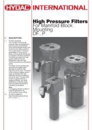
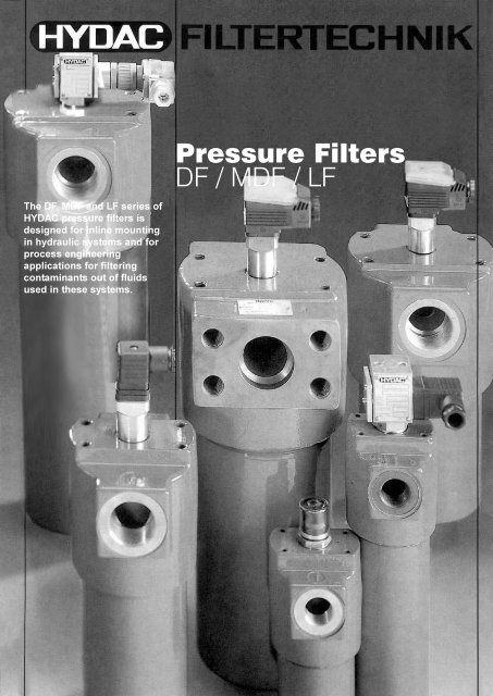
The DF, MDF and LF series of<br />
HYDAC pressure filters is<br />
designed for inline mounting<br />
in hydraulic systems and for<br />
process engineering<br />
applications for filtering<br />
contaminants out of fluids<br />
used in these systems.<br />
<strong>Pressure</strong> <strong>Filters</strong><br />
DF / MDF / LF
1. DESCRIPTION<br />
1.1. FILTER HOUSING<br />
1.1.1 Basic design<br />
<strong>Filters</strong> of the DF, MDF and LF<br />
series consist of the filter head<br />
and a screw-in filter bowl.<br />
Size 660 of the DF filter is also<br />
available with a two-piece bowl<br />
(tube and cover plate) as an<br />
additional version. When<br />
changing the element, sizes 500<br />
and 660 have the advantages of<br />
diamond knurling and a ring on<br />
the bowl. For size 990 and above<br />
the two-piece bowl version is<br />
used.<br />
The standard models of the DF,<br />
MDF and LF are supplied without<br />
a bypass valve. Moreover, sizes<br />
30 to 280 are supplied without a<br />
pressure release plug. Size 330<br />
and above are supplied with a<br />
pressure release plug as<br />
standard. The connection for a<br />
clogging indicator is available as<br />
standard.<br />
Model with one-piece bowl<br />
Outlet Inlet<br />
Model with two-piece bowl<br />
filter element<br />
BN3HC<br />
BH3HC<br />
V/HC<br />
W/HC<br />
Outlet Inlet<br />
filter element<br />
BN3HC<br />
BH3HC<br />
V/HC<br />
W/HC<br />
1.1.2 Materials<br />
DF SERIES:<br />
Filter Head: GGG 40<br />
Filter Bowl: Cold impact<br />
formed steel<br />
MDF SERIES:<br />
Filter Head: GGG 40<br />
Filter Bowl: Cold impact<br />
formed steel<br />
LF SERIES:<br />
Filter Head: Al<br />
Filter Bowl: Size 30 - 330: Al<br />
Size 660:<br />
Cold impact<br />
formed steel<br />
1.1.3 Seals<br />
NBR (Perbunan)<br />
1.1.4 Special models<br />
– <strong>Filters</strong> with protective finish<br />
– <strong>Filters</strong> with bypass valve<br />
– <strong>Filters</strong> with pressure release plug<br />
(size 280 and below)<br />
– Viton seals<br />
1.1.5 Accessories<br />
– Visual and/or electrical clogging<br />
indicator.<br />
The clogging indicators must be<br />
tightened to the recommended<br />
torque ratings,<br />
(see brochure no.: E 7.050../..)<br />
– Mating flanges for filters with<br />
SAE flange connection.<br />
1.2. NOTE<br />
For larger flow rates and lower<br />
pressure ranges, see brochure:<br />
Inline <strong>Filters</strong> (RFL)<br />
no.: E 7.104../..<br />
For stainless steel filters,<br />
see brochure:<br />
Industrial Processing <strong>Filters</strong><br />
no.: E 7.700../..<br />
Stainless steel filters also<br />
available for offshore applications.<br />
For information, contact our<br />
sales/technical department.<br />
1.2.1 Filter elements<br />
See Filter Element brochure<br />
no.: E 7.200../..<br />
1.2.2 Cleaning of elements<br />
Please note:<br />
Only wire mesh (W) and metal<br />
fibre (V) elements can be<br />
cleaned.<br />
Filter elements with<br />
Betamicron ® -H or Betamicron ® -N<br />
filter material cannot be cleaned.<br />
1.2.3 Spare parts<br />
See brochure: Spare Parts and<br />
Maintenance Instructions,<br />
no. E 7.501.E./..<br />
2. TECHNICAL<br />
SPECIFICATIONS<br />
2.1 GENERAL<br />
2.1.1 Designation and hydraulic<br />
symbols<br />
High pressure filter DF<br />
Medium pressure filter MDF<br />
Inline filter LF<br />
Filter without clogging indicator,<br />
without bypass valve (A)<br />
Filter without clogging indicator,<br />
with bypass valve (A../-B6)<br />
Filter with visual clogging<br />
indicator (B)<br />
Filter with electrical clogging<br />
indicator (C)<br />
Filter with visual and electrical<br />
clogging indicator (D)<br />
The lamp can either be fitted<br />
to the normally open contact (3)<br />
or the normally closed contact (2)<br />
2
2.1.2 Model Code<br />
(also order example)<br />
Filter Type<br />
DF high pressure filter<br />
MDF medium pressure filter<br />
LF inline filter<br />
Filter element material<br />
BH/HC Betamicron ® -H3HC element ⎤ absolute<br />
BN/HC Betamicron ® -N3HC element ⎦ filtration<br />
V/HC metal fibre element ⎤ nominal<br />
W/HC wire mesh element ⎦ filtration<br />
Size<br />
DF 30/60/110/140/160/240/280/330/500/660 1) /990/1320<br />
MDF 30/60/110/160/240<br />
LF 30/60/110/160/240/330/660<br />
Type of connection<br />
G threaded connection<br />
F flange connection<br />
Filtration rate in µm<br />
3 ⎤<br />
5 ⎥ Betamicron® -H (BH3HC) ⎤ absolute<br />
10 ⎥ Betamicron® -N (BN3HC) ⎦ filtration<br />
20 ⎦ metal fibre (V) ⎤ nominal<br />
25 wire mesh (W/HC) ⎦ filtration<br />
Type of clogging indicator<br />
A<br />
B<br />
C<br />
D<br />
= without clogging indicator<br />
= with visual clogging indicator<br />
= with electrical clogging indicator<br />
= with combined visual and electrical indicator<br />
⎤ see separate<br />
⎥ brochure on<br />
⎥ clogging indicators<br />
⎦ brochure no.: E 7.050../..<br />
Type code<br />
1 = standard connection for inlet and outlet (one-piece filter bowl)<br />
2 = standard connection for inlet and outlet (two-piece filter bowl) sizes 660 to 1320<br />
Modification number<br />
1<br />
DF BH/HC 60 G 10 C 1 . 1 / -V<br />
Supplementary details<br />
no details = standard<br />
-V = FPM (Viton) seals, filter suitable for phosphate ester (HFD-R)<br />
-W = NBR (Perbunan) seals, filter suitable for oil-water emulsion (HFA), water polymer solution (HFC)<br />
-L24 = light with 24 V DC ⎤<br />
-L48 = light with 48 V DC ⎥ on type "D"<br />
-L110 = light with 110 V DC ⎥ indicators only<br />
-L220 = light with 220 V DC ⎥<br />
-LED = 2 light emitting diodes for up to 24 V DC ⎦<br />
-B6 = with bypass valve (cracking pressure 6 bar)<br />
-SO 184= pressure release/oil drain plug (up to size 280)<br />
1) for DF series, this filter is available with type code 1 and 2<br />
3
2.1.3 Type of construction<br />
Inline filter<br />
2.1.4 Mounting method<br />
4 mounting holes in filter head<br />
2.1.5 Approx. weights<br />
with without<br />
element element<br />
DF 30 1.9 kg 1.8 kg<br />
DF 60 4.1 kg 3.9 kg<br />
DF 110 6.0 kg 5.7 kg<br />
DF 140 6.6 kg 6.2 kg<br />
DF 160 9.6 kg 9.1 kg<br />
DF 240 11.3 kg 10.6 kg<br />
DF 280 15.9 kg 14.5 kg<br />
DF 330 22.6 kg 21.4 kg<br />
DF 500 26.9 kg 25.2 kg<br />
DF 660 2) 30.5 kg 28.3 kg<br />
DF 660 3) 36.2 kg 34.0 kg<br />
DF 990 43.4 kg 40.0 kg<br />
DF1320 52.4 kg 48.0 kg<br />
MDF 30 1.9 kg 1.8 kg<br />
MDF 60 3.2 kg 3.0 kg<br />
MDF110 3.7 kg 3.2 kg<br />
MDF160 7.2 kg 6.7 kg<br />
MDF240 8.1 kg 7.4 kg<br />
LF 30 0.8 kg 0.7 kg<br />
LF 60 1.5 kg 1.3 kg<br />
LF 110 1.8 kg 1.5 kg<br />
LF 160 3.7 kg 3.2 kg<br />
LF 240 4.3 kg 3.6 kg<br />
LF 330 8.2 kg 7.0 kg<br />
LF 660 17.8 kg 15.6 kg<br />
2.1.6 Housing volumes<br />
Filter type LF and DF<br />
Size Volume<br />
30 0.13 l<br />
60 0.20 l<br />
110 0.33 l<br />
140 1) 0.40 l<br />
160 0.60 l<br />
240 0.80 l<br />
280 1) 1.45 l<br />
330 1.50 l<br />
500 1) 2.30 l<br />
660 3.00 l<br />
990 1) 4.20 l<br />
1320 1) 5.60 l<br />
Filter type MDF<br />
Size Volume<br />
30 0.10 l<br />
60 0.18 l<br />
110 0.32 l<br />
160 0.55 l<br />
240 0.79 l<br />
1) for DF series only<br />
2) size 660, type code 2<br />
3) size 660, type code 1<br />
2.1.7 Pipe connection sizes<br />
(threaded connection to ISO 228)<br />
and the relevant type codes<br />
DF 30 G G ½ 1.1<br />
DF 60 G G ¾ 1.1<br />
DF 110 G G ¾ 1.1<br />
DF 140 G G ¾ 1.1<br />
DF 160 G G 1 ¼ 1.1<br />
DF 240 G G 1 ¼ 1.1<br />
DF 280 G G 1 ¼ 1.1<br />
DF 330 G G 1 ½ 1.1<br />
DF 330 F SAE flange 1.1<br />
DN 50 / 6000 psi<br />
DF 500 G G 1 ½ 1.1<br />
DF 500 F SAE flange 1.1<br />
DN 50 / 6000 psi<br />
DF 660 G G 1 ½ 1.1<br />
2.1<br />
DF 990 G G 1 ½ 2.1<br />
DF 990 F SAE flange 2.1<br />
DN 50 / 6000 psi<br />
DF 1320 G G 1 ½ 2.1<br />
DF 1320 F SAE flange 2.1<br />
DN 50 / 6000 psi<br />
MDF 30 G G ½ 1.1<br />
MDF 60 G G ¾ 1.1<br />
MDF 110 G G ¾ 1.1<br />
MDF 160 G G 1 ¼ 1.1<br />
MDF 240 G G 1 ¼ 1.1<br />
LF 30 G G ½ 1.1<br />
LF 60 G G ¾ 1.1<br />
LF 110 G G ¾ 1.1<br />
LF 160 G G 1 ¼ 1.1<br />
LF 240 G G 1 ¼ 1.1<br />
LF 330 G G 1 ½ 1.1<br />
LF 660 G G 1 ½ 1.1<br />
2.1.8 Mounting position<br />
Vertical<br />
2.1.9 Flow direction<br />
Inlet and outlet: side connection<br />
At the same level, on<br />
opposite sides.<br />
2.2. HYDRAULIC DATA<br />
2.2.1 Operating pressure/<br />
temperature<br />
The operating pressure is<br />
generally dependent on the<br />
operating temperature.<br />
The following apply:<br />
δ min…δ max…= -10 °C…+100 °C<br />
DF 30 - 660 3) : p max = 420 bar<br />
DF 660 2) - 1320: p max = 315 bar<br />
(420 bar available on request)<br />
MDF all sizes: p max = 210 bar<br />
LF all sizes: p max = 100 bar<br />
δ min…δ max…= -30 °C…-10 °C<br />
only possible with Perbunan<br />
(NBR) seals.<br />
DF 30 - 660 3) : p max = 210 bar<br />
DF 660 2) - 1320: p max = 157.5 bar<br />
LF sizes 30 - 330: p max = 100 bar<br />
LF size 660: p max = 75 bar<br />
Proof of fatigue strength for<br />
complete filters to HYDAC test<br />
standard. Min. 1 mill. stress<br />
cycles, from 0 bar to permissible<br />
operating pressure (= p max ).<br />
For other temperature ranges,<br />
please contact our sales/technical<br />
department.<br />
2.2.2 Permissible ∆p across element<br />
Betamicron ® -H (BH3HC): 210 bar<br />
Betamicron ® -N (BN3HC): 25 bar<br />
Metal fibre (V): 210 bar<br />
Wire mesh (W): 30 bar<br />
2.2.3 Compatibility with<br />
hydraulic media<br />
Mineral oils:<br />
test criteria to ISO 2943<br />
Lubricating oils:<br />
test criteria to ISO 2943<br />
Suitable for use with non-flam<br />
fluids, synthetic oils and rapidly<br />
biodegradable oils. For use with<br />
water please check with our<br />
sales/technical department.<br />
2.2.4 Flow fatigue resistance<br />
to ISO 3724<br />
High fatigue resistance due to<br />
solid filter material supports on<br />
both sides and high inherent<br />
stability of filter materials.<br />
2.2.5 <strong>Pressure</strong> setting of<br />
clogging indicator<br />
∆pa = 5 bar - 10%<br />
2.2.6 Cracking pressure of<br />
bypass valve<br />
∆p = 6 bar + 10%<br />
O<br />
2.2.7 Bypass valve graphs<br />
The bypass valve graphs apply<br />
to mineral oil with a density of<br />
0.86 kg/dm³.<br />
The differential pressure of the<br />
valve changes proportionally to<br />
the density.<br />
∆p in bar<br />
A: sizes: 0660 D… E: sizes: 0110 D…<br />
B: sizes: 0500 D… / 0030 D…<br />
C: sizes: 0280 D… F: sizes: 0240 D…<br />
D: sizes: 0330 D… G:sizes: 0160 D…<br />
/ 0140 D… / 0060 D…<br />
Q in l/min as a % value of the size<br />
4
2.3. HOUSING GRAPHS<br />
The housing graphs apply to<br />
mineral oil with a density of<br />
0.86 kg/dm³ and a kinematic<br />
viscosity of 30 mm²/s.<br />
For turbulent flows the differential<br />
pressure changes proportionally<br />
to the density.<br />
For laminar flows the pressure<br />
changes proportionally to the<br />
density and the viscosity.<br />
DF/MDF/LF 30<br />
∆p in bar<br />
∆p in bar<br />
∆p in bar<br />
∆p in bar<br />
Q in l/min<br />
DF/MDF/LF 60/110/140*<br />
Q in l/min<br />
DF/MDF/LF 160/240/280*<br />
Q in l/min<br />
DF/LF 330/500*/660/990*/1320*<br />
* only for DF model<br />
Q in l/min<br />
3. FILTER CALCULATION<br />
3.1. TOTAL DIFFERENTIAL<br />
PRESSURE ACROSS THE<br />
COMPLETE FILTER<br />
The total differential pressure of<br />
the clean filter is the sum of<br />
housing and element differential<br />
pressure at operating viscosity.<br />
∆p =<br />
total<br />
∆p + f x ∆p housing at Q element at Q<br />
∆p = total differential<br />
total<br />
pressure across<br />
complete filter<br />
∆p = housing differential<br />
housing at Q<br />
(obtainable from housing graphs<br />
see point 2.3.)<br />
∆p = element differential<br />
element at Q<br />
pressure at 30 mm²/s<br />
at max. flow in l/min:<br />
(obtainable from element graphs<br />
see brochure no. E 7.200/..,<br />
Filter Elements)<br />
f = viscosity conversion factor -<br />
see point 3.1.1.<br />
3.1.1 Viscosity conversion factor f<br />
factor f<br />
3.1.2 Calculation guidelines<br />
Due to the high contamination<br />
retention capacity of the<br />
Betamicron ® elements, we<br />
recommend that the calculation of<br />
the filters (with clean element and<br />
at operating viscosity) be based<br />
on the following initial pressure<br />
drop:<br />
∆p total = 0.2 x pressure setting of<br />
clogging indicator.<br />
For pressure setting of clogging<br />
indicator see point 2.2.5.<br />
Other calculations are possible,<br />
depending on the system.<br />
An approximate calculation of the<br />
filter size can be made by means<br />
of the pre-selection chart - see<br />
point 3.2.<br />
operating viscosity (mm²/s)<br />
5
3.2. FILTER PRE-SELECTION<br />
CHART<br />
The pre-selection chart applies to<br />
a viscosity of 30 mm²/s at the<br />
usual hydraulic loads and<br />
favourable application conditions<br />
and applies to the following filters:<br />
Filter type: DF, MDF, LF<br />
Element type: ...D...BN3HC and<br />
...D...BH3HC<br />
The following example explains<br />
the procedure using the preselection<br />
chart:<br />
Example:<br />
System related details:<br />
Flow rate of variable<br />
displacement pump:<br />
Q p = 120 - 350 l/min<br />
Max. operating pressure:<br />
p B = 280 bar<br />
Required filtration rating:<br />
5 µm absolute<br />
Filter material:<br />
BH3HC<br />
Method:<br />
Determination of filter type<br />
Max. operating pressure:<br />
p B = 280 bar<br />
thus p B ≤ p max<br />
⇒ filter type: DF (see point 2.2.1)<br />
Determination of calculation<br />
flow rate Q A<br />
Q A = max. flow rate through<br />
the filter<br />
Q A = Q p max. = 350 l/min<br />
Determination of filter size<br />
For a calculation flow rate of<br />
Q A = 200 l/min and a filtration<br />
rating of 5 µm absolute, the filter<br />
size according to the<br />
pre-selection chart is 500<br />
Filter type:<br />
DF BH/HC 500 .. 5 ..<br />
12345678901234567890123456789012123456789012345<br />
12345678901234567890123456789012123456789012345<br />
Size 30 - 140<br />
12345678901234567890123456789012123456789012345<br />
12345678901234567890123456789012123456789012345<br />
12345678901234567890123456789012123456789012345<br />
12345678901234567890123456789012123456789012345<br />
12345678901234567890123456789012123456789012345<br />
12345678901234567890123456789012123456789012345<br />
12345678901234567890123456789012123456789012345<br />
12345678901234567890123456789012123456789012345<br />
12345678901234567890123456789012123456789012345<br />
12345678901234567890123456789012123456789012345<br />
12345678901234567890123456789012123456789012345<br />
12345678901234567890123456789012123456789012345<br />
12345678901234567890123456789012123456789012345<br />
12345678901234567890123456789012123456789012345<br />
12345678901234567890123456789012123456789012345<br />
12345678901234567890123456789012123456789012345<br />
12345678901234567890123456789012123456789012345<br />
Q in l/min<br />
12345678901234567890123456789012123456789012345<br />
12345678901234567890123456789012123456789012345<br />
12345678901234567890123456789012123456789012345<br />
12345678901234567890123456789012123456789012345<br />
12345678901234567890123456789012123456789012345<br />
12345678901234567890123456789012123456789012345<br />
12345678901234567890123456789012123456789012345<br />
12345678901234567890123456789012123456789012345<br />
12345678901234567890123456789012123456789012345<br />
12345678901234567890123456789012123456789012345<br />
12345678901234567890123456789012123456789012345<br />
12345678901234567890123456789012123456789012345<br />
12345678901234567890123456789012123456789012345<br />
<strong>Filters</strong> with Betamicron 12345678901234567890123456789012123456789012345<br />
12345678901234567890123456789012123456789012345<br />
12345678901234567890123456789012123456789012345<br />
12345678901234567890123456789012123456789012345<br />
12345678901234567890123456789012123456789012345<br />
® elements<br />
∆p = 1.5 bar<br />
Viscosity 30 mm²/s<br />
12345678901234567890123456789012123456789012345<br />
12345678901234567890123456789012123456789012345<br />
12345678901234567890123456789012123456789012345<br />
12345678901234567890123456789012123456789012345<br />
12345678901234567890123456789012123456789012345<br />
12345678901234567890123456789012123456789012345<br />
12345678901234567890123456789012123456789012345<br />
12345678901234567890123456789012123456789012345<br />
12345678901234567890123456789012123456789012345<br />
12345678901234567890123456789012123456789012345<br />
12345678901234567890123456789012123456789012345<br />
12345678901234567890123456789012123456789012345<br />
12345678901234567890123456789012123456789012345<br />
12345678901234567890123456789012123456789012345<br />
12345678901234567890123456789012123456789012345<br />
12345678901234567890123456789012123456789012345<br />
Size 160 - 280<br />
12345678901234567890123456789012123456789012345<br />
12345678901234567890123456789012123456789012345<br />
12345678901234567890123456789012123456789012345<br />
12345678901234567890123456789012123456789012345<br />
12345678901234567890123456789012123456789012345<br />
12345678901234567890123456789012123456789012345<br />
12345678901234567890123456789012123456789012345<br />
12345678901234567890123456789012123456789012345<br />
12345678901234567890123456789012123456789012345<br />
12345678901234567890123456789012123456789012345<br />
12345678901234567890123456789012123456789012345<br />
12345678901234567890123456789012123456789012345<br />
12345678901234567890123456789012123456789012345<br />
12345678901234567890123456789012123456789012345<br />
Q in l/min Q in l/min<br />
12345678901234567890123456789012123456789012345<br />
12345678901234567890123456789012123456789012345<br />
12345678901234567890123456789012123456789012345<br />
12345678901234567890123456789012123456789012345<br />
12345678901234567890123456789012123456789012345<br />
12345678901234567890123456789012123456789012345<br />
12345678901234567890123456789012123456789012345<br />
12345678901234567890123456789012123456789012345<br />
12345678901234567890123456789012123456789012345<br />
12345678901234567890123456789012123456789012345<br />
<strong>Filters</strong> with Betamicron 12345678901234567890123456789012123456789012345<br />
12345678901234567890123456789012123456789012345<br />
12345678901234567890123456789012123456789012345<br />
12345678901234567890123456789012123456789012345<br />
12345678901234567890123456789012123456789012345<br />
® elements<br />
∆p = 1.5 bar<br />
Viscosity 30 mm²/s<br />
12345678901234567890123456789012123456789012345<br />
12345678901234567890123456789012123456789012345<br />
12345678901234567890123456789012123456789012345<br />
12345678901234567890123456789012123456789012345<br />
12345678901234567890123456789012123456789012345<br />
12345678901234567890123456789012123456789012345<br />
12345678901234567890123456789012123456789012345<br />
12345678901234567890123456789012123456789012345<br />
12345678901234567890123456789012123456789012345<br />
12345678901234567890123456789012123456789012345<br />
12345678901234567890123456789012123456789012345<br />
Size 330 - 1320<br />
12345678901234567890123456789012123456789012345<br />
12345678901234567890123456789012123456789012345<br />
12345678901234567890123456789012123456789012345<br />
12345678901234567890123456789012123456789012345<br />
12345678901234567890123456789012123456789012345<br />
12345678901234567890123456789012123456789012345<br />
12345678901234567890123456789012123456789012345<br />
12345678901234567890123456789012123456789012345<br />
12345678901234567890123456789012123456789012345<br />
12345678901234567890123456789012123456789012345<br />
12345678901234567890123456789012123456789012345<br />
12345678901234567890123456789012123456789012345<br />
12345678901234567890123456789012123456789012345<br />
12345678901234567890123456789012123456789012345<br />
12345678901234567890123456789012123456789012345<br />
12345678901234567890123456789012123456789012345<br />
12345678901234567890123456789012123456789012345<br />
12345678901234567890123456789012123456789012345<br />
12345678901234567890123456789012123456789012345<br />
12345678901234567890123456789012123456789012345<br />
12345678901234567890123456789012123456789012345<br />
12345678901234567890123456789012123456789012345<br />
12345678901234567890123456789012123456789012345<br />
12345678901234567890123456789012123456789012345<br />
12345678901234567890123456789012123456789012345<br />
<strong>Filters</strong> with Betamicron 12345678901234567890123456789012123456789012345<br />
12345678901234567890123456789012123456789012345<br />
12345678901234567890123456789012123456789012345<br />
12345678901234567890123456789012123456789012345<br />
® elements<br />
∆p = 1.5 bar<br />
Viscosity 30 mm²/s<br />
12345678901234567890123456789012123456789012345<br />
12345678901234567890123456789012123456789012345<br />
12345678901234567890123456789012123456789012345<br />
12345678901234567890123456789012123456789012345<br />
12345678901234567890123456789012123456789012345<br />
12345678901234567890123456789012123456789012345<br />
12345678901234567890123456789012123456789012345<br />
12345678901234567890123456789012123456789012345<br />
12345678901234567890123456789012123456789012345<br />
12345678901234567890123456789012123456789012345<br />
12345678901234567890123456789012123456789012345<br />
12345678901234567890123456789012123456789012345<br />
6
4. DIMENSIONS<br />
DF/MDF/LF 30 G DF/LF 60 - 660 G<br />
MDF 60 - 240 G<br />
DF/LF 660 - 1320 G<br />
Threaded connection to ISO 228<br />
DF/LF 330 - 1320 F<br />
flange connection to ISO/DIS 6261<br />
SAE J 518 C 6000 psi (420 bar)<br />
DF 330 - 1320 G/F<br />
Dimensions in mm<br />
Typ b1 b 2 b3 b4 Ød1 Ød2 d 3 d 4 Ød5 h 1 h2 h 3 h 4 h 5 SW t 1 * t 2*<br />
LF 30 G 69 33 45 30 67 52 G½ M 5 – 125.5 35 7 75 – 24 15 6<br />
LF<br />
LF<br />
60 G<br />
110 G<br />
92 50 56 32 84 68 G¾ M 6<br />
–<br />
–<br />
137.5<br />
205.0<br />
40 6 75<br />
–<br />
–<br />
27 17 9<br />
LF<br />
LF<br />
160 G<br />
240 G<br />
128 65 85 35 116 95 G1¼ M10<br />
–<br />
–<br />
190.5<br />
250.5<br />
47 6 95<br />
–<br />
–<br />
32 21 14<br />
LF<br />
LF<br />
330 G<br />
660 G<br />
162 85 115 60 159<br />
130<br />
127<br />
G1½ M12<br />
–<br />
–<br />
252.5<br />
417.5<br />
50 6 105<br />
–<br />
–<br />
36 23 17<br />
DF/MDF 30 G 68/ 33/ 45/ 30/ 67/ 52/ G½ M 5 – 127.5/ 34/ 7 75 – 24 15 6<br />
66 54 43 21 60 45<br />
130 36<br />
DF/MDF 60 G<br />
DF/MDF 110 G<br />
DF 140 G<br />
93/<br />
92<br />
50/<br />
66<br />
56 32<br />
84/<br />
78<br />
68/<br />
59<br />
G¾ M 6<br />
–<br />
–<br />
–<br />
137.5/133<br />
205 /201<br />
248.5<br />
40 6<br />
85/<br />
75<br />
–<br />
–<br />
–<br />
27 17 9<br />
DF/MDF 160 G<br />
128/<br />
124<br />
65/<br />
80<br />
85 35 117/<br />
DF/MDF 240 G<br />
DF 280 G<br />
112<br />
95/<br />
84<br />
G1¼ M10<br />
–<br />
–<br />
–<br />
193.5/178<br />
253.5/237<br />
435.5<br />
47 6<br />
105/<br />
85<br />
–<br />
–<br />
–<br />
32 21 14<br />
DF 330 G 167<br />
G1½<br />
– 255.5<br />
–<br />
DF 330 F 160 SAE DN 50 – 255.5 –<br />
DF<br />
DF<br />
500 G<br />
500 F<br />
167<br />
160<br />
138 115 60 159 130<br />
G1½<br />
SAE DN 50<br />
M12<br />
–<br />
–<br />
348.5<br />
348.5<br />
52 6 115<br />
–<br />
–<br />
36 23 17<br />
DF 660 G 167 G1½ – 426.0 –<br />
DF 660 F 160 SAE DN 50 – –<br />
DF<br />
1)<br />
660 G 167<br />
G1½<br />
420<br />
350<br />
DF 660 F<br />
1)<br />
160 SAE DN 50 420 350<br />
DF<br />
DF<br />
990 G<br />
990 F<br />
167<br />
160<br />
138 115 60 159 132<br />
G1½<br />
SAE DN 50<br />
M12 152<br />
576<br />
576<br />
52 6<br />
500<br />
500<br />
112 36 23 17<br />
DF 1320 G 167 G1½ 742 670<br />
DF 1320 F 160 SAE DN 50 742 670<br />
* =thread depth<br />
1) =size 660 with type code 2<br />
5. NOTE<br />
All details in this brochure are subject to technical modifications.<br />
7