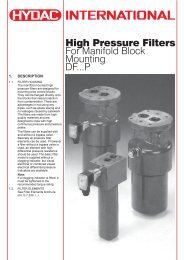
Pressure Filters
Pressure Filters
Pressure Filters

Create successful ePaper yourself
Turn your PDF publications into a flip-book with our unique Google optimized e-Paper software.
2.1.3 Type of construction<br />
Inline filter<br />
2.1.4 Mounting method<br />
4 mounting holes in filter head<br />
2.1.5 Approx. weights<br />
with without<br />
element element<br />
DF 30 1.9 kg 1.8 kg<br />
DF 60 4.1 kg 3.9 kg<br />
DF 110 6.0 kg 5.7 kg<br />
DF 140 6.6 kg 6.2 kg<br />
DF 160 9.6 kg 9.1 kg<br />
DF 240 11.3 kg 10.6 kg<br />
DF 280 15.9 kg 14.5 kg<br />
DF 330 22.6 kg 21.4 kg<br />
DF 500 26.9 kg 25.2 kg<br />
DF 660 2) 30.5 kg 28.3 kg<br />
DF 660 3) 36.2 kg 34.0 kg<br />
DF 990 43.4 kg 40.0 kg<br />
DF1320 52.4 kg 48.0 kg<br />
MDF 30 1.9 kg 1.8 kg<br />
MDF 60 3.2 kg 3.0 kg<br />
MDF110 3.7 kg 3.2 kg<br />
MDF160 7.2 kg 6.7 kg<br />
MDF240 8.1 kg 7.4 kg<br />
LF 30 0.8 kg 0.7 kg<br />
LF 60 1.5 kg 1.3 kg<br />
LF 110 1.8 kg 1.5 kg<br />
LF 160 3.7 kg 3.2 kg<br />
LF 240 4.3 kg 3.6 kg<br />
LF 330 8.2 kg 7.0 kg<br />
LF 660 17.8 kg 15.6 kg<br />
2.1.6 Housing volumes<br />
Filter type LF and DF<br />
Size Volume<br />
30 0.13 l<br />
60 0.20 l<br />
110 0.33 l<br />
140 1) 0.40 l<br />
160 0.60 l<br />
240 0.80 l<br />
280 1) 1.45 l<br />
330 1.50 l<br />
500 1) 2.30 l<br />
660 3.00 l<br />
990 1) 4.20 l<br />
1320 1) 5.60 l<br />
Filter type MDF<br />
Size Volume<br />
30 0.10 l<br />
60 0.18 l<br />
110 0.32 l<br />
160 0.55 l<br />
240 0.79 l<br />
1) for DF series only<br />
2) size 660, type code 2<br />
3) size 660, type code 1<br />
2.1.7 Pipe connection sizes<br />
(threaded connection to ISO 228)<br />
and the relevant type codes<br />
DF 30 G G ½ 1.1<br />
DF 60 G G ¾ 1.1<br />
DF 110 G G ¾ 1.1<br />
DF 140 G G ¾ 1.1<br />
DF 160 G G 1 ¼ 1.1<br />
DF 240 G G 1 ¼ 1.1<br />
DF 280 G G 1 ¼ 1.1<br />
DF 330 G G 1 ½ 1.1<br />
DF 330 F SAE flange 1.1<br />
DN 50 / 6000 psi<br />
DF 500 G G 1 ½ 1.1<br />
DF 500 F SAE flange 1.1<br />
DN 50 / 6000 psi<br />
DF 660 G G 1 ½ 1.1<br />
2.1<br />
DF 990 G G 1 ½ 2.1<br />
DF 990 F SAE flange 2.1<br />
DN 50 / 6000 psi<br />
DF 1320 G G 1 ½ 2.1<br />
DF 1320 F SAE flange 2.1<br />
DN 50 / 6000 psi<br />
MDF 30 G G ½ 1.1<br />
MDF 60 G G ¾ 1.1<br />
MDF 110 G G ¾ 1.1<br />
MDF 160 G G 1 ¼ 1.1<br />
MDF 240 G G 1 ¼ 1.1<br />
LF 30 G G ½ 1.1<br />
LF 60 G G ¾ 1.1<br />
LF 110 G G ¾ 1.1<br />
LF 160 G G 1 ¼ 1.1<br />
LF 240 G G 1 ¼ 1.1<br />
LF 330 G G 1 ½ 1.1<br />
LF 660 G G 1 ½ 1.1<br />
2.1.8 Mounting position<br />
Vertical<br />
2.1.9 Flow direction<br />
Inlet and outlet: side connection<br />
At the same level, on<br />
opposite sides.<br />
2.2. HYDRAULIC DATA<br />
2.2.1 Operating pressure/<br />
temperature<br />
The operating pressure is<br />
generally dependent on the<br />
operating temperature.<br />
The following apply:<br />
δ min…δ max…= -10 °C…+100 °C<br />
DF 30 - 660 3) : p max = 420 bar<br />
DF 660 2) - 1320: p max = 315 bar<br />
(420 bar available on request)<br />
MDF all sizes: p max = 210 bar<br />
LF all sizes: p max = 100 bar<br />
δ min…δ max…= -30 °C…-10 °C<br />
only possible with Perbunan<br />
(NBR) seals.<br />
DF 30 - 660 3) : p max = 210 bar<br />
DF 660 2) - 1320: p max = 157.5 bar<br />
LF sizes 30 - 330: p max = 100 bar<br />
LF size 660: p max = 75 bar<br />
Proof of fatigue strength for<br />
complete filters to HYDAC test<br />
standard. Min. 1 mill. stress<br />
cycles, from 0 bar to permissible<br />
operating pressure (= p max ).<br />
For other temperature ranges,<br />
please contact our sales/technical<br />
department.<br />
2.2.2 Permissible ∆p across element<br />
Betamicron ® -H (BH3HC): 210 bar<br />
Betamicron ® -N (BN3HC): 25 bar<br />
Metal fibre (V): 210 bar<br />
Wire mesh (W): 30 bar<br />
2.2.3 Compatibility with<br />
hydraulic media<br />
Mineral oils:<br />
test criteria to ISO 2943<br />
Lubricating oils:<br />
test criteria to ISO 2943<br />
Suitable for use with non-flam<br />
fluids, synthetic oils and rapidly<br />
biodegradable oils. For use with<br />
water please check with our<br />
sales/technical department.<br />
2.2.4 Flow fatigue resistance<br />
to ISO 3724<br />
High fatigue resistance due to<br />
solid filter material supports on<br />
both sides and high inherent<br />
stability of filter materials.<br />
2.2.5 <strong>Pressure</strong> setting of<br />
clogging indicator<br />
∆pa = 5 bar - 10%<br />
2.2.6 Cracking pressure of<br />
bypass valve<br />
∆p = 6 bar + 10%<br />
O<br />
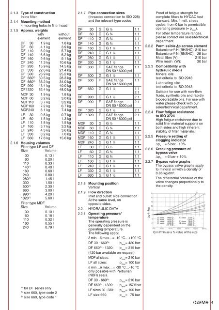
2.2.7 Bypass valve graphs<br />
The bypass valve graphs apply<br />
to mineral oil with a density of<br />
0.86 kg/dm³.<br />
The differential pressure of the<br />
valve changes proportionally to<br />
the density.<br />
∆p in bar<br />
A: sizes: 0660 D… E: sizes: 0110 D…<br />
B: sizes: 0500 D… / 0030 D…<br />
C: sizes: 0280 D… F: sizes: 0240 D…<br />
D: sizes: 0330 D… G:sizes: 0160 D…<br />
/ 0140 D… / 0060 D…<br />
Q in l/min as a % value of the size<br />
4