Profibus DP
Profibus DP
Profibus DP

Create successful ePaper yourself
Turn your PDF publications into a flip-book with our unique Google optimized e-Paper software.
MSystem<br />
Communication P<strong>DP</strong>-TP<br />
Card Description<br />
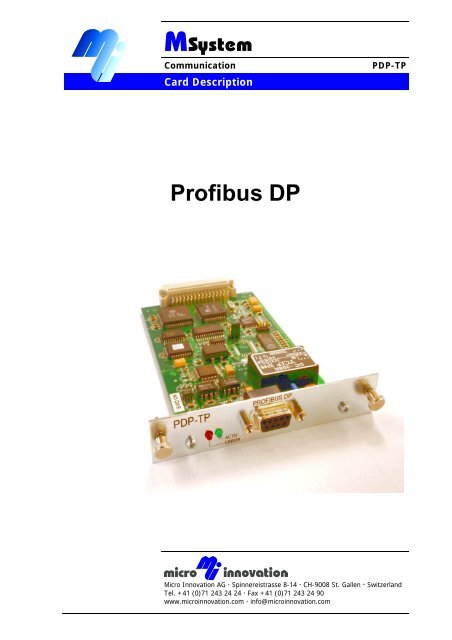
<strong>Profibus</strong> <strong>DP</strong><br />
Micro Innovation AG Spinnereistrasse 8-14 CH-9008 St. Gallen Switzerland<br />
Tel. +41 (0)71 243 24 24 Fax +41 (0)71 243 24 90<br />
www.microinnovation.com <br />
info@microinnovation.com
Card Description P<strong>DP</strong>-TP Communication<br />
Copyright<br />
Copyright<br />
Keep documentation for future use<br />
This documentation is the intellectual property of Micro Innovation AG, which also has the exclusive<br />
copyright. Any modification of the content, duplication or reprinting of this documentation, as well as<br />
any distribution to third parties can only be made with the express permission of Micro Innovation<br />
AG.<br />
Micro Innovation AG does not accept any liability for damages arising from the use of any incorrect<br />
or incomplete information contained in this documentation or any information missing therefrom.<br />
Micro Innovation AG reserves the right to make complete or partial modifications to this document.<br />
All brand and product names are trademarks or registered trademarks of the owner concerned.<br />
2<br />
Subject to technical modifications<br />
M000872-01.DOC<br />
© by Micro Innovation
Communication Card Description P<strong>DP</strong>-TP<br />
Proper use<br />
Proper use<br />
Hardware, software, operating systems and drivers must only be used for the<br />
applications specified and only in conjunction with the components recommended by<br />
Micro Innovation AG.<br />
Warning<br />
No warranty claims will be recognised for faults arising from the improper handling of<br />
devices and modules.<br />
The devices, even by means of communication, should not be used for the<br />
implementation of any safety functions relating to the protection of personnel and<br />
machinery.<br />
No liability is accepted for claims for damages arising from a failure or functional<br />
defect in the device.<br />
All data specified in this document does not represent warranted properties in the<br />
legal sense.<br />
Subject to technical modifications<br />
M000872-01.DOC<br />
© by Micro Innovation<br />
3
Card Description P<strong>DP</strong>-TP Communication<br />
Contents<br />
Contents<br />
1 Introduction......................................................................................................... 5<br />
2 LED elements ...................................................................................................... 6<br />
3 Connector assignment ....................................................................................... 7<br />
4 Preparation of the <strong>Profibus</strong> cable (bus cable).................................................. 8<br />
4.1 <strong>Profibus</strong> topology..................................................................................................... 8<br />
4.2 Bus cable................................................................................................................. 8<br />
4.3 Cable lengths........................................................................................................... 8<br />
4.4 Shield connection / potential equalisation ............................................................... 9<br />
4.5 Bus plug connector.................................................................................................. 9<br />
4.6 Line termination ....................................................................................................... 9<br />
5 Firmware............................................................................................................ 10<br />
6 Change list ........................................................................................................ 11<br />
4<br />
Subject to technical modifications<br />
M000872-01.DOC<br />
© by Micro Innovation
Communication Card Description P<strong>DP</strong>-TP<br />
Introduction<br />
1 INTRODUCTION<br />
This documentation is designed as a reference for connecting, commissioning and operating the P<strong>DP</strong>-<br />
TP communication card.<br />
This can only be used in MICRO PANEL devices which are provided with an appropriate slot (target<br />
hardware).<br />
The card must only be fitted and removed when the device is in a de-energized state.<br />
The number of drivers supported depends on the current firmware version. See “P<strong>DP</strong>-TP V X.YY<br />
Driver List”.<br />
If there is no driver for your PLC type available in the current version, please enquire about any newer<br />
versions with an extended range of drivers.<br />
The P<strong>DP</strong>-TP card supports the <strong>Profibus</strong> <strong>DP</strong> protocol and functions solely as a class B slave. This<br />
development is based on the EN50170 standard.<br />
Subject to technical modifications<br />
M000872-01.DOC<br />
© by Micro Innovation<br />
5
Card Description P<strong>DP</strong>-TP Communication<br />
LED elements<br />
2 LED ELEMENTS<br />
FRONT PANEL<br />
P<strong>DP</strong>-TP<br />
ACTIV<br />
ERROR<br />
PROFIBUS <strong>DP</strong><br />
ERROR When this ERROR LED (red) is lit, the last data transmission to the PLC could not<br />
be executed correctly.<br />
The LED will not go out until the next data transmission with the PLC was carried out<br />
correctly.<br />
This LED should never be lit in normal operation.<br />
ACTIV Green LED, lit during active data transmission between the P<strong>DP</strong>-TP and the PLC.<br />
In normal operation, this LED should flash momentarily (approx. 50 ms) with every<br />
data transmission.<br />
6<br />
20<br />
Subject to technical modifications<br />
M000872-01.DOC<br />
© by Micro Innovation
Communication Card Description P<strong>DP</strong>-TP<br />
Connector assignment<br />
3 CONNECTOR ASSIGNMENT<br />
The plug connector (Sub-D 9pole plug connector, female) and the connector assignment comply with<br />
the <strong>Profibus</strong> standard (EN50170). Only the mandatory signals and the power supply for line<br />
termination are provided.<br />
PROFIBUS <strong>DP</strong><br />
Sub-D 9 pole female<br />
Pin No. Assignment<br />
1 --- ---<br />
2 --- ---<br />
3 RxD/TxD-P Receive/Transmit-Data-P<br />
4 CNTR-P Control-P (Rep. Control)<br />
5 DGND Data Ground (Termination)<br />
6 VP Voltage-Plus (Termination)<br />
7 --- ---<br />
8 RxD/TxD-N Receive/Transmit-Data-N<br />
9 --- ---<br />
Case Shield<br />
The power supply terminals Data Ground (0V, Pin 5) and Voltage-Plus (+5V, Pin 6) are used for the<br />
power supply of the cable termination and must not be used for anything else. The Control-P (Pin 4)<br />
signal is used in conjunction with a repeater. Data is transferred via both the Rxd/Txd-P (<strong>Profibus</strong> →<br />
B/B‘ / RS-485 → non-inverted I/O) and Rxd/TxD-N (<strong>Profibus</strong> → A/A‘ / RS-485 → inverted I/O)<br />
terminals.<br />
Subject to technical modifications<br />
M000872-01.DOC<br />
© by Micro Innovation<br />
7
Card Description P<strong>DP</strong>-TP Communication<br />
Preparation of the <strong>Profibus</strong> cable (bus cable)<br />
4 PREPARATION OF THE PROFIBUS CABLE (BUS CABLE)<br />
The preparation of the bus cabling on the <strong>Profibus</strong> network is an essential factor in ensuring reliable<br />
operation and electromagnetic compatibility (EMC) on both the <strong>Profibus</strong> card and the target hardware.<br />
The EMC values (immunity and emission) specified in the technical data of the target hardware<br />
can only be guaranteed if the following cable preparation is completed.<br />
The <strong>Profibus</strong> cable (topology, cable, connectors, termination) must be prepared in compliance with the<br />
<strong>Profibus</strong> standard (EN50170).<br />
4.1 PROFIBUS TOPOLOGY<br />
A <strong>Profibus</strong> network must be configured as a linear topology through all bus stations, and must be<br />
terminated at both ends. Branches and spur lines are not permitted. A bus segment can connect up to<br />
32 bus stations with each other. Several bus segments can be linked by means of repeaters<br />
(bidirectional amplifiers).<br />
4.2 BUS CABLE<br />
Data is transferred in the <strong>Profibus</strong> network via shielded twisted pair cables. Only use type A cables as<br />
specified in the <strong>Profibus</strong> standard (EN50170).<br />
Rated ripple resistance : 150 Ohm (135...165 Ohm)<br />
Capacitance per unit length : < 30 pF/m<br />
Loop resistance : > 110 Ohm/km<br />
Core cross section : ≥ 0.34 mm 2 (22 AWG)<br />
4.3 CABLE LENGTHS<br />
The physical interface of the <strong>Profibus</strong> is based on the EIA RS 485 standard (differential voltage<br />
transmission). The corresponding cable length limits and wiring recommendations apply.<br />
The following lengths for a bus segment apply to cables in compliance with the <strong>Profibus</strong> standard<br />
(EN50170) for cable type A.<br />
Baud rate in<br />
Kbit/s<br />
9.6 1200<br />
19.2 1200<br />
93.75 1200<br />
187.5 1000<br />
500 400<br />
1500 200<br />
12000 100<br />
Length in m<br />
Non-observation of these limits may cause transmission errors.<br />
8<br />
Subject to technical modifications<br />
M000872-01.DOC<br />
© by Micro Innovation
Communication Card Description P<strong>DP</strong>-TP<br />
Preparation of the <strong>Profibus</strong> cable (bus cable)<br />
4.4 SHIELD CONNECTION / POTENTIAL EQUALISATION<br />
Shielded twisted pair cables are used for the <strong>Profibus</strong> network. The braided shield must have as low<br />
an impedance as possible to the shield reference potential at each bus station.<br />
The connection between the cable shield and the shield reference potential (on the Micro Panel this is<br />
the metallic housing) must be implemented via the plug casing and the fixing screws of the Sub-D plug<br />
connector.<br />
The shield reference potential of the individual bus stations is usually connected with the protective<br />
conductor system. This may therefore cause potential differences which in turn may give rise to<br />
equalisation currents along the cable shield. A potential equalisation bar should be provided if the<br />
potential differences and compensation currents between the shield reference potentials are high.<br />
4.5 BUS PLUG CONNECTOR<br />
Only use bus plug connectors that are specified for use in the <strong>Profibus</strong> network. These connect both<br />
bus cables on a bus station and ensure that the cable shield is looped through with a low-impedance<br />
connection and connected to the shield reference potential of the bus station.<br />
These bus plug connectors contain the special <strong>Profibus</strong> cable termination that can be activated with a<br />
slide switch if required. Components are also integrated for compensating the capacitive load of the<br />
bus station as is required for bit rates over 1.5 Mbit.<br />
Recommended bus plug connector:<br />
Manufacturer : Siemens<br />
Designation: Bus plug connector for <strong>Profibus</strong><br />
Order No.: 6ES7 972-0BA10-0XA0 (Siemens)<br />
4.6 LINE TERMINATION<br />
The <strong>Profibus</strong> bus must be provided with line termination at both ends in compliance with the <strong>Profibus</strong><br />
standard. The termination is passive but is supplied from the bus station, and ensures a defined idle<br />
signal on the bus when there are no bus stations active (all bus stations are tri-state).<br />
VP (6)<br />
Rxd/TxD-P (3)<br />
Rxd/TxD-N (8)<br />
DGND (5)<br />
The bus segment must be terminated at both ends!<br />
390<br />
220<br />
390<br />
<strong>Profibus</strong> cable termination<br />
in accordance with<br />
EN50170<br />
No more than 2 bus terminations must be activated for each bus segment!<br />
At least one of the two bus terminations must be fed by the bus station!<br />
Operation without the correct bus termination of the <strong>Profibus</strong> network may cause transmission errors.<br />
Subject to technical modifications<br />
M000872-01.DOC<br />
© by Micro Innovation<br />
9
Card Description P<strong>DP</strong>-TP Communication<br />
Firmware<br />
5 FIRMWARE<br />
The firmware P<strong>DP</strong>-TP.BIN is loaded on a retentive (Flash) memory on the P<strong>DP</strong>-TP.<br />
The latest <strong>Profibus</strong> driver is loaded at the factory when the card is shipped. The driver can be updated<br />
at any time via a MICRO PANEL (see relevant documentation of the MICRO PANEL).<br />
J6 - PRG RUN<br />
The <strong>Profibus</strong> driver is started when in position RUN.<br />
A new driver can be loaded when in position PRG.<br />
80<br />
10<br />
J6<br />
130<br />
Subject to technical modifications<br />
M000872-01.DOC<br />
© by Micro Innovation<br />
108
Communication Card Description P<strong>DP</strong>-TP<br />
Change list<br />
6 CHANGE LIST<br />
Index Date / Signed Modifications<br />
01 11-2003/ SB Initial version<br />
02 01-2005 / LE Formatting/PDF adaption<br />
Subject to technical modifications<br />
M000872-01.DOC<br />
© by Micro Innovation<br />
11
Card Description P<strong>DP</strong>-TP Communication<br />
Change list<br />
Micro Innovation AG<br />
Spinnereistr 8-14<br />
CH-9008 St. Gallen<br />
Switzerland<br />
Tel : ++41- 71 243 24 24<br />
Fax : ++41- 71 243 24 90<br />
email : info@microinnovation.com<br />
homepage : http://www.microinnovation.com<br />
12<br />
Subject to technical modifications<br />
M000872-01.DOC<br />
© by Micro Innovation