RV DIGITAL SATELLITE ANTENNA with Digital ... - Winegard
RV DIGITAL SATELLITE ANTENNA with Digital ... - Winegard
RV DIGITAL SATELLITE ANTENNA with Digital ... - Winegard

You also want an ePaper? Increase the reach of your titles
YUMPU automatically turns print PDFs into web optimized ePapers that Google loves.
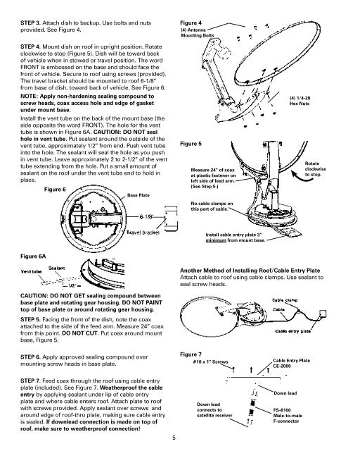
STEP 3. Attach dish to backup. Use bolts and nuts<br />
provided. See Figure 4.<br />
STEP 4. Mount dish on roof in upright position. Rotate<br />
clockwise to stop (Figure 5). Dish will be toward back<br />
of vehicle when in stowed or travel position. The word<br />
FRONT is embossed on the base and should face the<br />
front of vehicle. Secure to roof using screws (provided).<br />
The travel bracket should be mounted to roof 6-1/8”<br />
from base of dish, toward back of vehicle. See Figure 6.<br />
NOTE: Apply non-hardening sealing compound to<br />
screw heads, coax access hole and edge of gasket<br />
under mount base.<br />
Install the vent tube on the back of the mount base (the<br />
side opposite the word FRONT). The hole for the vent<br />
tube is shown in Figure 6A. CAUTION: DO NOT seal<br />
hole in vent tube. Put sealant around the outside of the<br />
vent tube, approximately 1/2” from end. Push vent tube<br />
into the hole. The sealant will seal the hole as you push<br />
in vent tube. Leave approximately 2 to 2-1/2” of the vent<br />
tube extending from the hole. Put a small amount of<br />
sealant on the roof under the vent tube end to hold in<br />
place.<br />
Figure 6<br />
Base Plate<br />
Figure 6A<br />
CAUTION: DO NOT GET sealing compound between<br />
base plate and rotating gear housing. DO NOT PAINT<br />
top of base plate or around rotating gear housing.<br />
STEP 5. Facing the front of the dish, note the coax<br />
attached to the side of the feed arm. Measure 24” coax<br />
from this point. DO NOT CUT. Put coax around mount<br />
base, Figure 5.<br />
STEP 6. Apply approved sealing compound over<br />
mounting screw heads in base plate.<br />
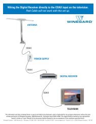
STEP 7. Feed coax through the roof using cable entry<br />
plate (included). See Figure 7. Weatherproof the cable<br />
entry by applying sealant under lip of cable entry<br />
plate and where cable enters roof. Attach plate to roof<br />
<strong>with</strong> screws provided. Apply sealant over screws and<br />
around edge of roof-thru plate, making sure cable entry<br />
is sealed. If downlead connection is made on top of<br />
roof, make sure to weatherproof connection!<br />
Figure 4<br />
(4) Antenna<br />
Mounting Bolts<br />
Figure 5<br />
Measure 24” of coax<br />
at plastic fastener on<br />
left side of feed arm.<br />
(See Step 5.)<br />
No cable clamps on<br />
this part of cable.<br />
Install cable entry plate 3”<br />
minimum from mount base.<br />
(4) 1/4-20<br />
Hex Nuts<br />
Rotate<br />
clockwise<br />
to stop.<br />
Another Method of Installing Roof/Cable Entry Plate<br />
Attach cable to roof using cable clamps. Use sealant to<br />
seal screw heads.<br />
Figure 7<br />
#10 x 1” Screws<br />
Down lead<br />
connects to<br />
satellite receiver<br />
Cable Entry Plate<br />
CE-2000<br />
Down lead<br />
FS-8100<br />
Male-to-male<br />
F-connector<br />
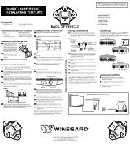
<strong>Digital</strong> Elevation Sensor Roof Connections<br />
The illustrations below show the different methods of connecting wires at roof level; method will depend on model.<br />
Wire colors must match, i.e. red to red, green to green, black to black.<br />
Supplied <strong>with</strong> DM-2000 only<br />
This wire harness connects to the digital<br />
elevation sensor on the antenna.<br />
3M UR TERMINAL<br />
Squeeze pliers until<br />
DO NOT STRIP<br />
red plunger is flush<br />
Snap<br />
wires. Terminal<br />
<strong>with</strong> rest of terminal.<br />
connectors<br />
is self-stripping.<br />
(Pliers not supplied.)<br />
Slide wires all the way in.<br />
together<br />
Inside <strong>RV</strong><br />
NOTE: This terminal is NOT WEATHERPROOF<br />
and CANNOT be left outside on the roof.<br />
For roof thickness greater than 6-1/2”.<br />
Parts Needed: (not included)<br />
14” worm gear for roof<br />
Directional handle extension<br />
Figure 8<br />
Long threaded rod<br />
Threaded Rod,<br />
Washer and Nut<br />
Instructions:<br />
STEP 8. Place nut on threaded rod. See Figure 8.<br />
STEP 9. Measure and cut the threaded rod <strong>with</strong> a<br />
hacksaw. Use the chart (Figure 10) to determine the<br />
correct length.<br />
STEP 10. Remove the nut over the cut end of the<br />
threaded rod. This cleans the threads after cutting.<br />
STEP 11. Thread the cut end of the rod into the hub.<br />
STEP 12. Install the ceiling plate. The rotate/lock lever<br />
must point toward the rear of the vehicle.<br />
Be sure rotate/lock lever is pointing towards the rear<br />
of the vehicle and that the hole in ceiling plate aligns<br />
<strong>with</strong> hole in the ceiling.<br />
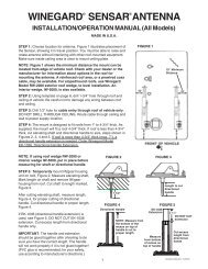
Refer to the chart to determine the correct length for<br />
the directional handle. Extensions may be needed. Each<br />
extension adds 2-1/4” to directional handle. DO NOT cut<br />
the extension. If the directional handle must be extended<br />
by less than 2-1/4”, cut the directional handle to fit.<br />
A tube cutter is recommended for cutting the<br />
directional handle. This gives a square cut; a hacksaw<br />
does not.<br />
Be sure large and small keyways line up in the hub and<br />
directional handle!<br />
Figure 9<br />
DIRECTIONAL<br />
HANDLE<br />
HANDLE<br />
LENGTH<br />
5 6<br />
NOTE: This terminal is weatherproof<br />
and can be left outside on the roof IF<br />
SECURED PROPERLY to prevent wind<br />
whipping.<br />
Figure 10<br />
Roof<br />
Thickness<br />
Directional<br />
Handle Length<br />
(Figure 9)<br />
Threaded<br />
Rod<br />
Length<br />
Worm Gear<br />
Shaft Length<br />
(Figure 11)<br />
1-1/2” ................2-7/8” ................. 2-3/4” ................. 2-7/8”<br />
1-3/4” ................3-1/4” ................. 3” ....................... 3-1/8”<br />
2” ......................3-1/2” ................. 3-1/4” ................. 3-1/2”<br />
2-1/4” ................3-7/8 ................... 3-1/2” ................. 3-7/8”<br />
2-1/2” ................4-1/8” ................. 3-3/4” ................. 4-1/8”<br />
2-3/4” ................4-1/2” ................. 4” ....................... 4-1/2”<br />
3” ......................4-3/4” ................. 4-1/4” ................. 4-3/4”<br />
3-1/4” ................5” ........................ 4-5/8” ................. 4-7/8”<br />
3-1/2” ................5-1/4” ................. 4-7/8” ................. 5-1/8”<br />
3-3/4” ................5-5/8” ................. 5-1/4” ................. 5-1/2”<br />
4” ......................5-3/4” ................. 5-1/2” ................. 5-3/4”<br />
4-1/4” ................6-1/8” ................. 5-3/4” ................. 6-1/8”<br />
4-1/2” ................6-1/2” ................. 6” ....................... 6-1/4”<br />
4-3/4” ................6-5/8” ................. 6-1/8” ................. 6-3/8”<br />
5” ......................6-7/8” ................. 6-3/8” ................. 6-5/8”<br />
5-1/4” ................7-1/8” ................. 6-5/8” ................. 7”<br />
5-1/2” ................7-3/8” ................. 6-7/8” ................. 7-1/4”<br />
5-3/4” ................7-5/8” ................. 7-1/4” ................. 7-1/2”<br />
6” ......................7-7/8” ................. 7-1/2” ................. 7-3/4”<br />
6-1/4” ................8-1/8” ................. 7” ....................... 8”<br />
6-1/2” ................8-1/2” ................. 7-3/4” ................. 8-1/4”<br />
6 3/4” ................8 3/4”.................. 8” ................... 8 1/2”<br />
7” ..................9” .................... 8 1/4” ................. 8 7/8”<br />
7-1/4” ................9-3/8” ................. 8 5/8” ................. 9 1/8<br />
7-1/2” ................9-5/8” ................. 8 7/8” ................. 9 3/8<br />
7-3/4” ................9-7/8” ................. 9 1/8” ................. 9 5/8<br />
8” ..................10-1/8” ............... 9 3/8” ................. 10<br />
8-1/4” ................10-3/8” ............... 9 5/8” ................. 10 1/4<br />
8-1/2” ................10-3/4” ............... 9 7/8” ................. 10 3/8<br />
8-3/4” ................11” .................. 10” ................. 10 5/8<br />
9” .................. 11-1/4” ............... 10-1/4” ............... 11<br />
9-1/4” ................ 11-1/2” ............... 10-5/8” ............... 11 1/4<br />
9-1/2” ................ 11-3/4” ............... 10 7/8” ............... 11 1/2<br />
9-3/4” ................ 12” ................. 11 1/8” ............... 11 3/4<br />
10” ................ 12-3/8” ............... 11 3/8” ............... 12<br />
10-1/4” .............. 12-5/8” ............... 11 5/8” ............... 12 1/4<br />
10-1/2” .............. 12-7/8” ............... 11 7/8” ............... 12 1/2