RV DIGITAL SATELLITE ANTENNA with Digital ... - Winegard
RV DIGITAL SATELLITE ANTENNA with Digital ... - Winegard
RV DIGITAL SATELLITE ANTENNA with Digital ... - Winegard

Create successful ePaper yourself
Turn your PDF publications into a flip-book with our unique Google optimized e-Paper software.
<strong>RV</strong> <strong>DIGITAL</strong> <strong>SATELLITE</strong> <strong>ANTENNA</strong><br />
<strong>with</strong> <strong>Digital</strong> Elevation Sensor<br />
Model RM-DM46<br />
may also be packaged as<br />
RM-DM00, RMDM04, RMFLDM4<br />
www.winegard.com<br />
For Technical Services, call 1-800-788-4417<br />
For Receivers and Programming, call 1-866-609-9374<br />
DO NOT RETURN <strong>ANTENNA</strong> TO PLACE OF PURCHASE.<br />
<strong>Winegard</strong> Company • 3000 Kirkwood Street • Burlington, IA 52601 • 800-288-8094 • Fax 319-754-0787<br />
www.winegard.com • Printed in U.S.A. ©2002 <strong>Winegard</strong> Company Rev9 2/12 2451069
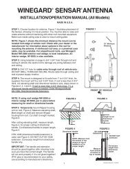
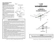
Operation<br />
STEP 1. The more accurately you determine North, the easier it is to locate the satellite. Step outside and away<br />
from your vehicle. (Standing too near to your vehicle can give incorrect compass readings.) It is helpful if there is<br />
a landmark on the horizon to represent North. Return to the vehicle and point the directional dial North or to the<br />
landmark.<br />
Figure 1<br />
Directional Handle<br />
Directional Handle Pointer<br />
Red screw<br />
240 250<br />
290<br />
300 310<br />
320 330 340 350<br />
POINT NORTH<br />
10<br />
20 30 40<br />
50<br />
60 70<br />
Elevating Crank<br />
(unsnap to pull handle down)<br />
Rotation Clamp<br />
Directional Dial<br />
STEP 2. Turn on receiver and television. Tune the television to channel 3 or 4. Using your receiver manual for<br />
instructions, go to the Signal Meter screen. Enter nearest zip code for your location using receiver’s remote control.<br />
After the zip code is entered, the receiver will indicate numbers for azimuth (compass heading) and elevation.<br />
Unsnap the elevating crank, and turn the elevation handle CLOCKWISE to raise the antenna. Turn the elevating crank<br />
COUNTERCLOCKWISE to lower the antenna.<br />
STEP 3. Press the button on the <strong>Winegard</strong> digital display wall plate. If antenna is in travel position, the display will<br />
show LL for Low Limit. HL for High Limit will appear when the dish is in up position.<br />
STEP 4. Crank the elevation handle to raise antenna. Stop cranking when the readout displays the correct elevation<br />
for your location, which is found on the receiver’s signal meter screen.<br />
STEP 5. Rotate antenna slowly until the correct satellite signal is acquired. NOTE: Rotate 3°, then stop. DO NOT rotate<br />
continuously, even if you are rotating slowly. If you notice the elevation angle has changed, it could be due to the<br />
following reasons:<br />
1. <strong>RV</strong> is not parked level.<br />
2. Antenna is mounted to a slightly sloped <strong>RV</strong> roof. (This is not a problem.)<br />
When you have rotated the antenna so it is facing in approximately the right azimuth (compass direction), simply<br />
adjust to correct elevation, and continue searching for signal.<br />
When you have detected the satellite signal, adjust the antenna up/down and left/right for the strongest signal the<br />
receiver displays. Due to variations in receivers and installation methods, you may find the elevation numbers (after<br />
peaking on the strongest signal) no longer match what the receiver recommended. This is normal. The elevation<br />
sensor should always get you close enough to pick up a signal to peak on. If the display turns off while you’re<br />
searching, just push the button for another minute of operation. After a little practice, finding the signal may only take<br />
30 to 50 seconds.<br />
Replacement Parts<br />
For replacement parts, contact <strong>Winegard</strong> Company at 1-800-288-8094 (credit card orders only, $5.00 minimum order).<br />
To order receivers or programming, please call the <strong>Winegard</strong> receiver hotline at 1-866-609-9374.<br />
Tuning Antenna<br />
STEP 1. Your receiver should indicate it is receiving a signal. To tune your antenna for the best signal strength,<br />
slowly move the antenna left, then right, until you have found the position that gives the highest signal strength. It is<br />
important to turn the antenna slowly. Because the signal is digital, the receiver takes a few seconds to lock on.<br />
STEP 2. Place rotation clamp in the LOCK position. This prevents antenna movement and loss of signal.<br />
STEP 3. Slowly raise then lower the antenna until you have peaked the signal. You are now ready to watch satellite TV!<br />
Lowering Antenna to Travel Position<br />
STEP 1. Set the rotation clamp to ROTATE position.<br />
STEP 2. Rotate antenna until pointer on directional handle aligns <strong>with</strong> the red screw on the rotation clamp.<br />
STEP 3. Turn elevating crank counterclockwise in direction of DOWN arrow until meeting resistance. The number of<br />
turns will vary according to the elevation angle the antenna was set at.<br />
STEP 4. Move rotation clamp to the LOCK position. Antenna is now locked in travel position.<br />
STEP 5. Snap elevation crank in place.<br />
CAUTION! NEVER LOWER <strong>ANTENNA</strong> IN ANY POSITION EXCEPT TRAVEL POSITION!<br />
1 2<br />
DOs<br />
1. Do check parking location for obstructions before raising antenna.<br />
2. Do carefully raise, lower and rotate antenna. If difficult, check for cause.<br />
3. Do rotate slowly when searching for the satellite(s), and check fine tuning on TV set to make sure it is properly<br />
adjusted.<br />
4. Do lower antenna before moving vehicle!<br />
5. Do activate programming by calling program provider for your receiver.<br />
DON’Ts<br />
1. Don’t move <strong>RV</strong>/coach <strong>with</strong> the antenna in the UP position. This will void your warranty and may also cause<br />
damage to your roof.<br />
2. Don’t force elevating crank up or down. Check for cause of trouble.<br />
3. Don’t rotate directional handle hard against stops.<br />
4. Don’t apply paint over top of base plate or anywhere on lift.<br />
5. Don’t apply sealant on gear housing.
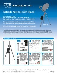
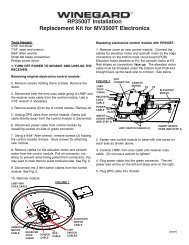
Troubleshooting Assembly & Installation<br />
Figure 2<br />
Antenna Reflector at 90°<br />
Signal from satellite<br />
24° look angle<br />
LNBF<br />
6. Check the TV. Does it receive pictures from off-air television stations/VCR?<br />
7. Re-tune system for best picture. See page 2.<br />
1. You may need to rotate the dish in small increments to find<br />
the signal. Rotate the dish 3° at a time to the left, stopping for<br />
a few seconds each time you move the dish. Try moving the<br />
dish up to 20° to the left. If no signal is found, return to the<br />
azimuth listed and try rotating 20° to the right. This will help<br />
correct for any errors in setting the directional handle.<br />
2. Be sure you have a clear line of sight. The signal from the<br />
satellite(s) will not pass through trees, buildings, mountains,<br />
etc. Remember the antenna has a 24° offset; this means that<br />
when the antenna is straight up and down (90°), it is looking<br />
24° into the sky. See Figure 2.<br />
3. Check that the TV set is tuned for the correct channel, 3 or 4<br />
(same channel as output of receiver).<br />
4. Check that you have entered the correct zip code of your<br />
current location. If the zip code is wrong, the antenna will be<br />
looking in the wrong direction or at the wrong elevation for<br />
the satellite signal.<br />
5. Check connections at the receiver, TV, and antenna.<br />
8. Inspect the antenna, making sure it has not been damaged. If the antenna is even slightly bent, the receiver may<br />
not receive the signal.<br />
9. Contact Dealer or <strong>Winegard</strong> Technical Services.<br />
If Antenna Does Not Rotate or Is Difficult to Rotate<br />
1. Inspect antenna on roof. Be sure the mount has not been damaged.<br />
2. Check for caulking between gear housing and base plate.<br />
3. Be sure cables are not binding and that they have been installed properly.<br />
4. Contact your dealer or <strong>Winegard</strong> Technical Services.<br />
If Antenna Does Not Raise or Is Difficult to Raise<br />
1. Inspect antenna on roof. Be sure the mount has not been damaged.<br />
2. Check for caulking on the elevating shaft.<br />
3. Contact your dealer or <strong>Winegard</strong> Technical Services.<br />
LCD DISPLAY CODES<br />
HL High Limit<br />
LL Low Limit<br />
Lo Battery Low<br />
Er Error<br />
-- Initializing<br />
NOTE: Initialization may take up to<br />
5 seconds.<br />
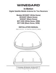
Supplies Needed<br />
Screwdrivers (Phillips and slot)<br />
1-3/4” hole saw<br />
7/16” wrench<br />
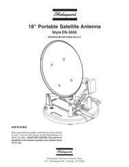
Figure 3<br />
34” DIAMETER<br />
OPERATING<br />
AREA<br />
17” RADIUS<br />
ABS glue<br />
Drill <strong>with</strong> 1/8” bit<br />
Tape measure<br />
<strong>Winegard</strong>’s <strong>Digital</strong> Elevation Sensor has been<br />
INSTALLED and CALIBRATED at the factory.<br />
MINIMUM<br />
10”<br />
3 4<br />
19.50”<br />
29”<br />
FRONT OF VEHCILE<br />
Non-hardening sealant<br />
(Check manufacturer’s specifications<br />
for compatibility <strong>with</strong> your roof.)<br />
STEP 1. Choose a location on the roof for the dish that will allow the dish to raise and rotate <strong>with</strong>out interfering <strong>with</strong><br />
other roof-mounted equipment. Make sure inside ceiling plate is easily accessible and <strong>with</strong> no obstructions that<br />
would interfere <strong>with</strong> operation.<br />
Figure 3 shows minimum distance (10”) antenna should be located from edge of vehicle roof. It is recommended<br />
that you check <strong>with</strong> your dealer or manufacturer for provisions that may have been made in the roof for antenna<br />
mounting, such as a reinforced roof area or pre-wire installation from the factory.<br />
The antenna must be level for proper<br />
operation!<br />
<strong>Winegard</strong> Model RW-5000 roof wedge <strong>with</strong> gasket is<br />
available. If inside roof wedge is needed, <strong>Winegard</strong><br />
Model RW-1000 can be trimmed to fit ceiling plate.<br />
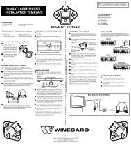
STEP 2. Position template on roof (see insert page of<br />
this manual). CAUTION: DO NOT drill through wiring.<br />
Carefully drill a 1-3/4” hole through roof and ceiling of<br />
vehicle. Inspect hole to make sure wiring is intact. See<br />
roof template insert.<br />
It is highly recommended the antenna be mounted<br />
on the center line of the roof. Do not mount antenna<br />
closer than 10” from roof edge.<br />
RW-5000<br />
Roof Wedge<br />
<strong>with</strong> gasket<br />
Vehicle Roof<br />
Antenna Controls<br />
NOT TO SCALE<br />
Interior<br />
Roof Wedge<br />
(Optional)
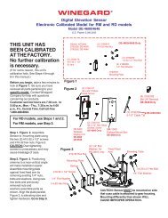
STEP 3. Attach dish to backup. Use bolts and nuts<br />
provided. See Figure 4.<br />
STEP 4. Mount dish on roof in upright position. Rotate<br />
clockwise to stop (Figure 5). Dish will be toward back<br />
of vehicle when in stowed or travel position. The word<br />
FRONT is embossed on the base and should face the<br />
front of vehicle. Secure to roof using screws (provided).<br />
The travel bracket should be mounted to roof 6-1/8”<br />
from base of dish, toward back of vehicle. See Figure 6.<br />
NOTE: Apply non-hardening sealing compound to<br />
screw heads, coax access hole and edge of gasket<br />
under mount base.<br />
Install the vent tube on the back of the mount base (the<br />
side opposite the word FRONT). The hole for the vent<br />
tube is shown in Figure 6A. CAUTION: DO NOT seal<br />
hole in vent tube. Put sealant around the outside of the<br />
vent tube, approximately 1/2” from end. Push vent tube<br />
into the hole. The sealant will seal the hole as you push<br />
in vent tube. Leave approximately 2 to 2-1/2” of the vent<br />
tube extending from the hole. Put a small amount of<br />
sealant on the roof under the vent tube end to hold in<br />
place.<br />
Figure 6<br />
Base Plate<br />
Figure 6A<br />
CAUTION: DO NOT GET sealing compound between<br />
base plate and rotating gear housing. DO NOT PAINT<br />
top of base plate or around rotating gear housing.<br />
STEP 5. Facing the front of the dish, note the coax<br />
attached to the side of the feed arm. Measure 24” coax<br />
from this point. DO NOT CUT. Put coax around mount<br />
base, Figure 5.<br />
STEP 6. Apply approved sealing compound over<br />
mounting screw heads in base plate.<br />
STEP 7. Feed coax through the roof using cable entry<br />
plate (included). See Figure 7. Weatherproof the cable<br />
entry by applying sealant under lip of cable entry<br />
plate and where cable enters roof. Attach plate to roof<br />
<strong>with</strong> screws provided. Apply sealant over screws and<br />
around edge of roof-thru plate, making sure cable entry<br />
is sealed. If downlead connection is made on top of<br />
roof, make sure to weatherproof connection!<br />
Figure 4<br />
(4) Antenna<br />
Mounting Bolts<br />
Figure 5<br />
Measure 24” of coax<br />
at plastic fastener on<br />
left side of feed arm.<br />
(See Step 5.)<br />
No cable clamps on<br />
this part of cable.<br />
Install cable entry plate 3”<br />
minimum from mount base.<br />
(4) 1/4-20<br />
Hex Nuts<br />
Rotate<br />
clockwise<br />
to stop.<br />
Another Method of Installing Roof/Cable Entry Plate<br />
Attach cable to roof using cable clamps. Use sealant to<br />
seal screw heads.<br />
Figure 7<br />
#10 x 1” Screws<br />
Down lead<br />
connects to<br />
satellite receiver<br />
Cable Entry Plate<br />
CE-2000<br />
Down lead<br />
FS-8100<br />
Male-to-male<br />
F-connector<br />
<strong>Digital</strong> Elevation Sensor Roof Connections<br />
The illustrations below show the different methods of connecting wires at roof level; method will depend on model.<br />
Wire colors must match, i.e. red to red, green to green, black to black.<br />
Supplied <strong>with</strong> DM-2000 only<br />
This wire harness connects to the digital<br />
elevation sensor on the antenna.<br />
3M UR TERMINAL<br />
Squeeze pliers until<br />
DO NOT STRIP<br />
red plunger is flush<br />
Snap<br />
wires. Terminal<br />
<strong>with</strong> rest of terminal.<br />
connectors<br />
is self-stripping.<br />
(Pliers not supplied.)<br />
Slide wires all the way in.<br />
together<br />
Inside <strong>RV</strong><br />
NOTE: This terminal is NOT WEATHERPROOF<br />
and CANNOT be left outside on the roof.<br />
For roof thickness greater than 6-1/2”.<br />
Parts Needed: (not included)<br />
14” worm gear for roof<br />
Directional handle extension<br />
Figure 8<br />
Long threaded rod<br />
Threaded Rod,<br />
Washer and Nut<br />
Instructions:<br />
STEP 8. Place nut on threaded rod. See Figure 8.<br />
STEP 9. Measure and cut the threaded rod <strong>with</strong> a<br />
hacksaw. Use the chart (Figure 10) to determine the<br />
correct length.<br />
STEP 10. Remove the nut over the cut end of the<br />
threaded rod. This cleans the threads after cutting.<br />
STEP 11. Thread the cut end of the rod into the hub.<br />
STEP 12. Install the ceiling plate. The rotate/lock lever<br />
must point toward the rear of the vehicle.<br />
Be sure rotate/lock lever is pointing towards the rear<br />
of the vehicle and that the hole in ceiling plate aligns<br />
<strong>with</strong> hole in the ceiling.<br />
Refer to the chart to determine the correct length for<br />
the directional handle. Extensions may be needed. Each<br />
extension adds 2-1/4” to directional handle. DO NOT cut<br />
the extension. If the directional handle must be extended<br />
by less than 2-1/4”, cut the directional handle to fit.<br />
A tube cutter is recommended for cutting the<br />
directional handle. This gives a square cut; a hacksaw<br />
does not.<br />
Be sure large and small keyways line up in the hub and<br />
directional handle!<br />
Figure 9<br />
DIRECTIONAL<br />
HANDLE<br />
HANDLE<br />
LENGTH<br />
5 6<br />
NOTE: This terminal is weatherproof<br />
and can be left outside on the roof IF<br />
SECURED PROPERLY to prevent wind<br />
whipping.<br />
Figure 10<br />
Roof<br />
Thickness<br />
Directional<br />
Handle Length<br />
(Figure 9)<br />
Threaded<br />
Rod<br />
Length<br />
Worm Gear<br />
Shaft Length<br />
(Figure 11)<br />
1-1/2” ................2-7/8” ................. 2-3/4” ................. 2-7/8”<br />
1-3/4” ................3-1/4” ................. 3” ....................... 3-1/8”<br />
2” ......................3-1/2” ................. 3-1/4” ................. 3-1/2”<br />
2-1/4” ................3-7/8 ................... 3-1/2” ................. 3-7/8”<br />
2-1/2” ................4-1/8” ................. 3-3/4” ................. 4-1/8”<br />
2-3/4” ................4-1/2” ................. 4” ....................... 4-1/2”<br />
3” ......................4-3/4” ................. 4-1/4” ................. 4-3/4”<br />
3-1/4” ................5” ........................ 4-5/8” ................. 4-7/8”<br />
3-1/2” ................5-1/4” ................. 4-7/8” ................. 5-1/8”<br />
3-3/4” ................5-5/8” ................. 5-1/4” ................. 5-1/2”<br />
4” ......................5-3/4” ................. 5-1/2” ................. 5-3/4”<br />
4-1/4” ................6-1/8” ................. 5-3/4” ................. 6-1/8”<br />
4-1/2” ................6-1/2” ................. 6” ....................... 6-1/4”<br />
4-3/4” ................6-5/8” ................. 6-1/8” ................. 6-3/8”<br />
5” ......................6-7/8” ................. 6-3/8” ................. 6-5/8”<br />
5-1/4” ................7-1/8” ................. 6-5/8” ................. 7”<br />
5-1/2” ................7-3/8” ................. 6-7/8” ................. 7-1/4”<br />
5-3/4” ................7-5/8” ................. 7-1/4” ................. 7-1/2”<br />
6” ......................7-7/8” ................. 7-1/2” ................. 7-3/4”<br />
6-1/4” ................8-1/8” ................. 7” ....................... 8”<br />
6-1/2” ................8-1/2” ................. 7-3/4” ................. 8-1/4”<br />
6 3/4” ................8 3/4”.................. 8” ................... 8 1/2”<br />
7” ..................9” .................... 8 1/4” ................. 8 7/8”<br />
7-1/4” ................9-3/8” ................. 8 5/8” ................. 9 1/8<br />
7-1/2” ................9-5/8” ................. 8 7/8” ................. 9 3/8<br />
7-3/4” ................9-7/8” ................. 9 1/8” ................. 9 5/8<br />
8” ..................10-1/8” ............... 9 3/8” ................. 10<br />
8-1/4” ................10-3/8” ............... 9 5/8” ................. 10 1/4<br />
8-1/2” ................10-3/4” ............... 9 7/8” ................. 10 3/8<br />
8-3/4” ................11” .................. 10” ................. 10 5/8<br />
9” .................. 11-1/4” ............... 10-1/4” ............... 11<br />
9-1/4” ................ 11-1/2” ............... 10-5/8” ............... 11 1/4<br />
9-1/2” ................ 11-3/4” ............... 10 7/8” ............... 11 1/2<br />
9-3/4” ................ 12” ................. 11 1/8” ............... 11 3/4<br />
10” ................ 12-3/8” ............... 11 3/8” ............... 12<br />
10-1/4” .............. 12-5/8” ............... 11 5/8” ............... 12 1/4<br />
10-1/2” .............. 12-7/8” ............... 11 7/8” ............... 12 1/2
STEP 13. The directional handle and threaded rod will<br />
fit roofs up to 5¼” thick. If you are using wedges to<br />
compensate for roof/ceiling slope, be sure to allow for<br />
this extra thickness. You may add an extension to the<br />
directional handle for thicker roofs. Each extension will<br />
increase the length of the directional handle by 2¼”.<br />
See Figure 11.<br />
Figure 11<br />
WITH ROOF WEDGE<br />
Measure from top of<br />
roof wedge to ceiling.<br />
TOP OF ROOF<br />
WEDGE<br />
WITHOUT ROOF WEDGE<br />
Measure from top of<br />
roof to ceiling.<br />
TOP OF ROOF<br />
CEILING<br />
CEILING<br />
STEP 14. Press the directional handle onto the hub.<br />
Point arrow on the directional handle towards the<br />
rotate/lock lever to orient to the splines.<br />
STEP 15. Install the washer and nut on the threaded<br />
rod. Tighten the nut enough to snug the directional<br />
handle to the hub.<br />
STEP 16. IF YOU ARE USING AN EXTENSION,<br />
adjust the total length of the directional handle and<br />
extension by cutting the directional handle.<br />
After adjusting parts for proper roof thickness, glue<br />
the extension to the directional handle. Use ABS<br />
(plastic pipe) glue.<br />
NOTE: For roofs over 5¼” thick, a longer aluminum<br />
hex shaft is needed. Contact <strong>Winegard</strong> for this part.<br />
7<br />
Figure 12<br />
Spacer<br />
Spring<br />
Worm<br />
Gear<br />
Threaded<br />
Rod<br />
Ceiling<br />
Plate<br />
Directional<br />
Handle<br />
Plastic Plug<br />
Cutting Shaft Length<br />
Flip down handle on the elevating crank handle. Slide<br />
elevating crank handle up shaft until snug against the<br />
directional handle.<br />
Mark the elevating shaft at the inside bottom surface of<br />
crank handle housing (Figure 13).<br />
After removing crank handle, cut<br />
shaft at mark. Re-install crank.<br />
Figure 13<br />
Elevating Shaft<br />
Cut elevating shaft at inside<br />
surface of crank handle<br />
housing; shaft goes through<br />
the hex-shaped opening by<br />
the screw.<br />
See template on reverse side.
ALIGN WITH<br />
Roof Template<br />
BASEPLATE<br />
AREA MARKED<br />
“FRONT”<br />
POINT TO FRONT<br />
OF VEHICLE<br />
<br />
1-3/4” DIA.<br />
DRILL COMPLETELY<br />
THROUGH CEILING<br />
1/8” DRILL BIT<br />
8 HOLES. DO NOT<br />
DRILL THROUGH CEILING.
See template on reverse side.<br />
CAUTION!<br />
After initial installation, the antenna SHOULD<br />
ROTATE APPROXIMATELY 360° FROM<br />
TRAVEL POSITION.<br />
The pointer on the directional handle should<br />
point towards the RED SCREW ON THE<br />
ROTATION CLAMP when in the TRAVEL<br />
POSITION.<br />
Figure 14<br />
240 250<br />
Pointer must<br />
point to RED<br />
SCREW at<br />
CENTER OF<br />
ROTATION<br />
CLAMP when<br />
in travel<br />
position.<br />
290<br />
300 310<br />
320 330 340 350<br />
POINT NORTH<br />
10<br />
POINT TO<br />
BACK OF <strong>RV</strong><br />
20 30 40<br />
CAUTION!<br />
The antenna must be in the travel position<br />
before aligning the directional handle and<br />
ceiling plate!<br />
50<br />
60 70<br />
Rotation<br />
Clamp<br />
Red Screw<br />
TIGHTEN SCREW SNUGLY!<br />
8<br />
Figure 15<br />
Figure 16<br />
Elevating Shaft<br />
Threaded Tube<br />
Directional Handle<br />
Extension<br />
Ceiling Plate<br />
(4) #10 Phillips<br />
Flat Head Screws<br />
Directional Handle<br />
ALIGN POINTER<br />
WITH <strong>ANTENNA</strong><br />
TRAVEL POSITION<br />
Elevating Crank<br />
Handle<br />
(When installed,<br />
extends 2-1/4”<br />
from ceiling.) Snap<br />
Handle into base<br />
when not in use.
<strong>Digital</strong> Elevation Sensor Interior Wall plate<br />
STEP 19. See Figure 17. If using the SM-1000 surface<br />
mount box, feed cable through hole in box.<br />
STEP 20. Connect wires coming from sensor on roof to<br />
wall plate display in vehicle. It is important<br />
to properly connect the wires at the roof<br />
and the wall plate. (Plug will click when<br />
inserted properly.) The system is<br />
designed to use a 9 volt battery OR<br />
+12 VDC from vehicle. Do not use<br />
both! IMPROPER WIRING WILL<br />
CAUSE DAMAGE TO THE PRODUCT.<br />
See Figure 18.<br />
SM-1000<br />
Surface Mount Box<br />
STEP 21. Pressing the button when<br />
the antenna is in a vertical position should display 24<br />
(+1°). The display will automatically turn off after 1<br />
minute.<br />
STEP 22. Check connectors and cable entry points. Be<br />
sure these areas are properly sealed to prevent water<br />
damage.<br />
Figure 18<br />
Snap battery in<br />
place, making sure<br />
battery terminals are<br />
firmly seated on wall<br />
plate terminals.<br />
Based on 5 minutes a day of usage, standard new alkaline<br />
batteries should last 88 days.<br />
OPERATION (Also on pages 1–2)<br />
STEP 23. Using satellite receiver, find correct elevation<br />
for your location. See the receiver manual for details of<br />
setup information.<br />
STEP 24. Press button on <strong>Winegard</strong> digital display wall<br />
plate. If antenna is in travel position, the display will<br />
show LL for Low Limit.<br />
STEP 25. Crank elevation handle to raise antenna.<br />
Stop when readout displays correct elevation for your<br />
location. (Found on receiver setup menu.)<br />
Figure 17<br />
Cable and plug from<br />
roof sensor unit;<br />
plugs into sensor<br />
Sensor to readout cable<br />
Readout assembly<br />
STEP 26. Rotate antenna VERY SLOWLY until correct<br />
satellite signal is acquired. Rotate 3°, and stop. DO NOT<br />
rotate continuously even if you’re rotating slowly. If<br />
the elevation angle has changed, it could be due to the<br />
following:<br />
• Vehicle is not parked level.<br />
• Antenna system mounted on slightly sloped roof. If<br />
this is the reason, after you have rotated the antenna to<br />
the approximately correct compass direction, adjust to<br />
correct elevation and continue search.<br />
Note: When you have found the satellite signal, adjust<br />
the antenna up/down and right/left for the strongest<br />
signal your receiver displays. Due to variation in<br />
receivers and installation methods, you may find the<br />
elevation numbers after peaking on strongest signal no<br />
longer match what the receiver display recommended.<br />
This is normal. The elevation sensor should always<br />
get you close enough to pick up a signal to peak on. If<br />
display turns off while you’re searching, just push the<br />
button for another minute of operation. With a little<br />
practice, most users find the signal in 30 to 50 seconds.<br />
9 10<br />
Screw<br />
Vent Tube<br />
Hub<br />
Parts List<br />
RP-RM46<br />
(Includes dir.<br />
handle extension<br />
and dir. handle)
Parts List<br />
RP-35RM<br />
Backup Frame<br />
Pivot Bracket<br />
Carriage Bolt<br />
(not shown)<br />
RP-RM00<br />
(Does not<br />
include LNB<br />
or Elevation<br />
Sensar)<br />
11 12<br />
Washer<br />
Parts Views
Notes<br />
13 14<br />
Notes
Specifications<br />
Antenna & Mount<br />
Height when raised: 30” vertical<br />
max.<br />
Height in the travel position: 8” max.<br />
Operating radius: 17”<br />
Roof space required: 26”<br />
Compatible <strong>with</strong> DIRECTV ® , DISH ® ,<br />
and Bell TV<br />
Weight: 12 lbs<br />
Color: cool gray<br />
Antenna height: 20.9”<br />
Antenna width: 19.2”<br />
F/D: 0.59<br />
Offset angle: 24 °<br />
Frequency range: 10.95–12.75 GHz<br />
Gain:<br />
11.2 GHz, 33.22 dBi<br />
12.1 GHz, 33.89 dBi<br />
12.6 GHz, 34.23 dBi<br />
Aperture efficiency: 73%<br />
Beamwidth at -3 dB: 3.5 °<br />
Beamwidth at -10 dB: 7.0 °<br />
Wind loading: up to hurricane force<br />
WINEGARD MOBILE PRODUCTS LIMITED WARRANTY<br />
(2 YEARS PARTS; 1 YEAR LABOR)<br />
<strong>Winegard</strong> Company warrants this product against defects in materials or workmanship for a period of two (2) years from the date of original<br />
purchase. During year one (1) of such warranty, <strong>Winegard</strong> Company will also pay authorized labor costs to an authorized <strong>Winegard</strong> dealer<br />
to repair or replace defective products. No warranty claim will be honored unless at the time the claim is made, Customer presents proof of<br />
purchase to an authorized <strong>Winegard</strong> dealer (to locate the nearest authorized <strong>Winegard</strong> dealer, contact <strong>Winegard</strong> Company, 3000 Kirkwood<br />
Street, Burlington, Iowa 52601, Telephone 800-288-8094 or visit www.winegard.com). Customer must provide proof of purchase <strong>with</strong> a dated<br />
sales receipt for the <strong>Winegard</strong> product to verify the product is under warranty. If the date of purchase cannot be verified, the warranty period<br />
shall be considered to begin thirty (30) days after the date of manufacture.<br />
If a defect in material or workmanship is discovered, Customer may take the product to an authorized <strong>Winegard</strong> dealer for service. Customer<br />
must provide proof of purchase to verify the product is under warranty. If the product is brought to an authorized <strong>Winegard</strong> dealer for service<br />
prior to expiration of year one (1) of the warranty period and a defect in material or workmanship is verified by <strong>Winegard</strong> Technical Services,<br />
<strong>Winegard</strong> Company will cover the <strong>Winegard</strong> dealer’s labor charges for warranty service. The <strong>Winegard</strong> dealer must contact <strong>Winegard</strong> Technical<br />
Services in advance for pre-approval of the service. Approval of the service is at the sole discretion of <strong>Winegard</strong> Company.<br />
Alternatively, Customer may ship the product prepaid to <strong>Winegard</strong> Technical Services (located at 3111 Kirkwood Street, Burlington, Iowa 52601,<br />
Telephone 800-788-4417). Customer must return the product along <strong>with</strong> a brief description of the problem and provide <strong>Winegard</strong> Technical Services<br />
<strong>with</strong> Customer’s name, address, and phone number. Customer must also provide proof of purchase to verify the product is under warranty. If<br />
the product is returned before the expiration of the warranty period, <strong>Winegard</strong> Company will (at its option) either repair or replace the product.<br />
This Limited Warranty does not apply if the product has been damaged, deteriorates, malfunctions or fails from: improper installation, misuse,<br />
abuse, neglect, accident, tampering, modification of the product as originally manufactured by <strong>Winegard</strong> in any manner whatsoever, removing<br />
or defacing any serial number, usage not in accordance <strong>with</strong> product instructions or acts of nature such as damage caused by wind, lightning,<br />
ice or corrosive environments such as salt spray and acid rain. This Limited Warranty also does not apply if the product becomes unable to<br />
perform its’ intended function in any way as a result of the television signal provider making any changes in technology or service.<br />
RETURN AUTHORIZATION POLICY<br />
A Return Material Authorization (RMA) is required prior to returning any product to <strong>Winegard</strong> Company or <strong>Winegard</strong> Warranty Services under<br />
this warranty policy. Please call our Technical Services Department at 800-788-4417 or send an e-mail to warranty@winegard.com to obtain<br />
the RMA number. Please furnish the date of purchase when requesting an RMA number. Enclose the product in a prepaid package and write<br />
the RMA number in large, clear letters on the outside of the package. To avoid confusion or misunderstanding, a shipment(s) <strong>with</strong>out an RMA<br />
number(s) or an unauthorized return(s) will be refused and returned to Customer freight collect.<br />
WINEGARD COMPANY DOES NOT ASSUME ANY LIABILITIES FOR ANY OTHER WARRANTIES, EXPRESS OR IMPLIED, MADE BY ANY OTHER<br />
PERSON.<br />
ALL OTHER WARRANTIES WHETHER EXPRESS, IMPLIED OR STATUTORY INCLUDING WARRANTIES OF FITNESS FOR A PARTICULAR<br />
PURPOSE AND MERCHANTABILITY ARE LIMITED TO THE TWO YEAR PERIOD OF THIS WARRANTY.<br />
In states that do not allow limitations on implied warranties, or the exclusion of limitation of incidental or consequential damages, the above<br />
limitations or exclusions do not apply.<br />
Some states do not allow limitations on how long an implied warranty lasts, or the exclusion of limitation of incidental or consequential<br />
damages, so the above limitations or exclusions may not apply to you.<br />
This warranty gives Customer specific legal rights. Customer may also have other rights that may vary from state to state.<br />
<strong>SATELLITE</strong> RECEIVER WARRANTY<br />
See manufacturer’s limited warranty policy<br />
WS-MOBWARREV2 Rev. 1/10<br />
Disclaimer: Although every effort has been made to ensure that the information in this manual is correct and complete, no company shall be<br />
held liable for any errors or omissions in this manual. Changes and technological advances are continuously being made in the satellite market.<br />
Information provided in this manual was accurate at time of printing. If the antenna does not function as expected, please contact <strong>Winegard</strong><br />
Company at 1-800-788-4417, or visit our website at www.winegard.com.<br />
<strong>Winegard</strong> Company • 3000 Kirkwood Street • Burlington, IA 52601 • 800-288-8094 • Fax 319-754-0787<br />
www.winegard.com • Printed in U.S.A. ©2002 <strong>Winegard</strong> Company Rev9 2/12 2451069<br />
<strong>Winegard</strong> is a registered trademarks of <strong>Winegard</strong> Company. DISH is a registered trademark of DISH Network L.L.C.<br />
DIRECTV is a registered trademark of DIRECTV, Inc., a unit of Hughes Electronics Corp. Bell TV is a trademark of Bell Canada, Inc.