EV-97 englisch - Keller AG
EV-97 englisch - Keller AG
EV-97 englisch - Keller AG

You also want an ePaper? Increase the reach of your titles
YUMPU automatically turns print PDFs into web optimized ePapers that Google loves.
<strong>EV</strong>-<strong>97</strong><br />
OPERATING MANUAL<br />
INTRODUCTION<br />
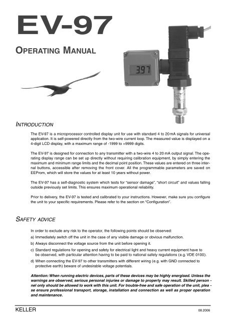
The <strong>EV</strong>-<strong>97</strong> is a microprocessor controlled display unit for use with standard 4 to 20 mA signals for unive r s a l<br />
a p p l i c a t i o n. It is self-powered directly from the two-wire current loop. The measured value is displayed on a<br />
4-digit LCD display, with a maximum range of -1999 to +9999 digits.<br />
The <strong>EV</strong>-<strong>97</strong> is designed for connection to any transmitter with a two-wire 4 to 20 mA output signal. The operating<br />
display range can be set up directly without requiring calibration equipment, by simply entering the<br />
maximum and minimum range limits and the decimal point position. These values are entered on three internal<br />
buttons, accessible after removing the front cover. All the programmable parameters are saved on<br />
EEProm, which will store the values for at least 10 years without power.<br />
The <strong>EV</strong>-<strong>97</strong> has a self-diagnostic system which tests for “sensor damage”, “short circuit” and values falling<br />
outside previously set limits. This ensures maximum operational reliability.<br />
Prior to delivery, the <strong>EV</strong>-<strong>97</strong> is tested and calibrated to your instructions. However, make sure you configure<br />
the unit to your specific requirements. Please refer to the section on “Configuration”.<br />
SAFETY ADVICE<br />
KELLER<br />
In order to exclude any risk to the operator, the following points should be observed:<br />
a) Immediately switch off the unit in the case of any visible damage or obvious malfunction.<br />
b) Always disconnect the voltage source from the unit before opening it.<br />
c) Standard regulations for opening and safety for electrical light and heavy current equipment have to<br />
be observed, with particular attention having to be paid to national safety regulations (e.g. VDE 0100).<br />
d) When connecting the <strong>EV</strong>-<strong>97</strong> to other transmitters with different wiring (e.g. with GND connected to<br />
protective earth) beware of undesirable voltage potentials.<br />
Attention: When running electric devices, parts of these devices may be highly energised. Unless the<br />
warnings are observed, serious personal injuries or damage to property may result. Skilled person -<br />
nel only should be allowed to work with this unit. For trouble-free and safe operation of the unit, plea -<br />
se ensure professional transport, storage, installation and connection as well as proper operation<br />
and maintenance.<br />
08.2006
ELECTRICAL CONNECTION<br />
<strong>EV</strong>-<strong>97</strong><br />
Remove the DIN 43650 connector from the pressure transmitter. Plug the <strong>EV</strong>-<strong>97</strong> onto the transmitter.<br />
O rientate as desired. Replace the DIN 43650 connector. Note that the locking screw will have to be replaced<br />
with the longer one supplied.<br />
Supply voltage: The <strong>EV</strong>-<strong>97</strong> is loop-powered from the measuring circuit.<br />
Electric connection and commissioning of the unit must be carried out by trained and skilled personnel.<br />
Wrong connection may lead to the destruction of the display unit, in which case we cannot assume any war -<br />
ranty. Do not exceed the maximum input current rating of 40 mA under any circumstances !<br />
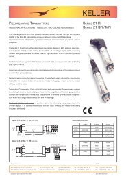
PLUG-CONNECTION<br />
This instrument is wired for operation with<br />
all KELLER 2-wire transmitters fitted with<br />
DIN 43650 connectors.<br />
CONNECTIONS (NOT POLARIZED):<br />
Standard (on Stock) 1 - 2<br />
Series 21/21R/21S 1 - 3<br />
Series 23(S)/25(S)/33(S)/35(S) 2 - 3<br />
The corresponding connections are marked<br />
on the packing.<br />
KELLER<br />
The polarity is not relevant!<br />
08.2006
TECHNICAL SPECIFICATION<br />
<strong>EV</strong>-<strong>97</strong><br />
Input signal: 4 to 20 mA (2-wire)<br />
Max. permissible input current: 40 mA<br />
Reverse voltage protection: Polarized installation<br />
Voltage load: Approx. 3 ,5 V<br />
Display: 10 mm high LCD-display<br />
Display range: Starting and end value freely selectable<br />
Maximum display value: 9999 digits<br />
Minimum display value: -1999 digits<br />
Decimal point: Any position<br />
Measuring accuracy: 0,2 % ± 1 digit<br />
Temperature drift: 100 ppm / °C<br />
Measuring interval: Approx. 5 measurements/ sec.<br />
Filter: 3 stages can be selected<br />
Nominal temperature: 25°C<br />
Ambient temperature: 0 to 50°C<br />
Relative atmospheric humidity: 0 to 80 % (non condensing)<br />
Electromagnetic compatibility: In accordance with EN50081-1 and EN50082-1<br />
additional error: < 1 %<br />
Housing: Case: ABS. Front screen: Polycarbonate.<br />
48,5 x 48,5 x 35,5 mm (L x W x D)<br />
Connection: Specially designed adaptor for use with DIN 43650<br />
connector (3 pole + earth).<br />
M3 x 75 mm screw supplied.<br />
IP rating: Front side IP65<br />
FAULT CODES<br />
FE1:<br />
FE2:<br />
KELLER<br />
In case of unacceptable conditions in the system a fault code will be displayed.<br />
Fault codes are defined as follows:<br />
Measuring range has been exceeded<br />
This fault code indicates that the measuring range of the A/D converter has been exceeded.<br />
Potential fault cause: Transmitter damaged.<br />
Short-circuit in transmitter connection.<br />
<strong>EV</strong>-<strong>97</strong> incorrectly configured.<br />
Remedies: FE1 will be reset as soon as the measuring values are back within<br />
their permissible range. Please check your transmitter and transmitter<br />
connecting cables.<br />
Measuring values have fallen below permissible range<br />
This fault code indicates that the measuring values of the A/D converter have fallen below the permissible<br />
range.<br />
Potential fault cause: Transmitter damaged.<br />
Transmitter connection interrupted.<br />
<strong>EV</strong>-<strong>97</strong> incorrectly configured.<br />
Remedies: FE2 will be reset as soon as the measuring values are back within<br />
their permissible range. Please check your transmitter and transmitter<br />
connecting cables.<br />
08.2006
<strong>EV</strong>-<strong>97</strong><br />
CONFIGURATION<br />
1.<br />
2.<br />
3.<br />
4.<br />
5.<br />
Press button 1, “dP” (decimal point) will be displayed.<br />
Select decimal point position desired using buttons 2 and 3.<br />
Acknowledge decimal point position by pressing button 1. “dP” will be displayed again.<br />
Press button 1 again. “An 4” (display for 4 mA) will be displayed.<br />
Buttons 2 and 3 will scroll the display up (button 2) and down (button 3) by 1 digit at a time, for 6 seconds.<br />
The scrolling speed will then increase.<br />
Acknowledge correct value by pressing button 1 again. The new value of “An 4” will be displayed.<br />
Switch to the next parameter by pressing button 1 once again. “An20” will be displayed (display for<br />
20 mA).<br />
Use buttons 2 and 3 to set value to be displayed on the <strong>EV</strong>-<strong>97</strong> for an input signal of 20 mA. Acknowledge<br />
value displayed by pressing button 1. “An20” will be displayed again.<br />
Press button 1 once again. “LI” (limit) will be displayed.<br />
Select measuring range limits required using buttons 2 and 3.<br />
0 = Values exceeding/ falling below limits are acceptable. (FE1, FE2 displayed for hardware limits).<br />
1 = Values exceeding/ falling below limits are not acceptable. (FE1, FE2 displayed for area limits).<br />
Acknowledge selection made by pressing button 1. “LI” will be displayed again. For pressure measuring<br />
t ransmitters always enter “LI 0”. For transmitters for relative humidity, pH and similar measuring units<br />
a l ways enter “LI 1”.<br />
Press button 1 once again. “FILt” (filter) will be displayed.<br />
Select input filter 0, 1, 2 or 3 required using buttons 2 and 3.<br />
0 = no filter<br />
1 = filter 1 active<br />
2 = filter 2 active<br />
3 = filter 1 and filter 2 active<br />
Filter 1: For filtering the short spikes generated by adjacent relays or contactors, activate “FILt 1”.<br />
Additional delay: approx. 0,5 s.<br />
Filter 2: To prevent “jumping” of the last digit, a phenomenon often found in digital displays, activate<br />
“FILt 2”. This is recommended if the display range exceeds 2000 digits.<br />
Additional display delay: approx. 1 s.<br />
Acknowledge selection made by pressing button 1 again. “FILt” will be displayed.<br />
Button 2 Button 1 Button 3<br />
The adjustment of the <strong>EV</strong>-<strong>97</strong> to the transmitter is now completed. The <strong>EV</strong>-<strong>97</strong> can be switched over to display<br />
the current measuring value by pressing button 1.<br />
http://www.keller-druck.ch<br />
08.2006<br />
KELLER <strong>AG</strong> für Druckmesstechnik St. Gallerstrasse 119 CH-8404 Winterthur Tel. 052-235 25 25 Fax 052-235 25 00<br />
KELLER EUROPE Schwarzwaldstrasse 17 D-7<strong>97</strong>98 Jestetten Tel. 07745-9214-0 Fax 07745-9214-50