Impedance Characteristics of Log Periodic Antenna - International ...
Impedance Characteristics of Log Periodic Antenna - International ...
Impedance Characteristics of Log Periodic Antenna - International ...
You also want an ePaper? Increase the reach of your titles
YUMPU automatically turns print PDFs into web optimized ePapers that Google loves.
<strong>International</strong> Journal <strong>of</strong> Computer Applications (0975 – 8887)<br />
Volume 21– No.1, May 2011<br />
<strong>Impedance</strong> <strong>Characteristics</strong> <strong>of</strong> <strong>Log</strong> <strong>Periodic</strong> <strong>Antenna</strong><br />
B. I. Neelgar<br />
GMR Institute <strong>of</strong> Technology<br />
GMR Nagar,<br />
Rajam-532127, Srikakulum (Dist)<br />
A. P. (India)<br />
ABSTRACT<br />
<strong>Log</strong> <strong>Periodic</strong> array <strong>Antenna</strong> is one <strong>of</strong> the most important and<br />
commercially used antennas for T.V. reception. It is used in<br />
VHF and UHF bands. Although the analysis <strong>of</strong> this antenna is<br />
reported in literature, the data <strong>of</strong> self impedance & mutual<br />
impedance is not fully available. But, this data is useful for the<br />
optimal design <strong>of</strong> the antenna. In view <strong>of</strong> this the array above is<br />
considered and the analysis is carried out in the present work.<br />
The computed data for Self-<strong>Impedance</strong> as a function <strong>of</strong> lengths<br />
<strong>of</strong> elements and frequency and the Mutual <strong>Impedance</strong> as a<br />
function <strong>of</strong> spacings <strong>of</strong> elements is presented.<br />
Keywords<br />
<strong>Log</strong>-<strong>Periodic</strong>, Self <strong>Impedance</strong>, Mutual <strong>Impedance</strong>, Hertzian<br />
Dipole<br />
1. INTRODUCTION<br />
<strong>Log</strong> <strong>Periodic</strong> antenna introduced by DuHamel and Isbell [1] is<br />
frequency independent antenna which has a structural geometry<br />
such that its impedance is periodic with logarithm <strong>of</strong> the<br />
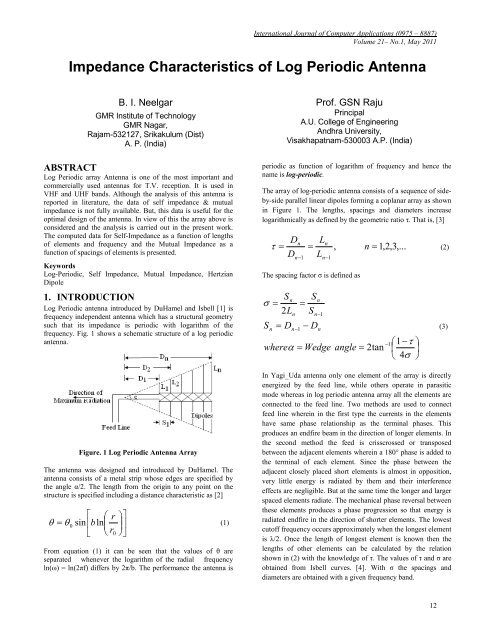
frequency. Fig. 1 shows a schematic structure <strong>of</strong> a log periodic<br />
antenna.<br />
Figure. 1 <strong>Log</strong> <strong>Periodic</strong> <strong>Antenna</strong> Array<br />
The antenna was designed and introduced by DuHamel. The<br />
antenna consists <strong>of</strong> a metal strip whose edges are specified by<br />
the angle α/2. The length from the origin to any point on the<br />
structure is specified including a distance characteristic as [2]<br />
⎡ ⎛ r ⎞⎤<br />
= θ ⎢ ⎜<br />
⎟<br />
0 sin bln<br />
⎥<br />
⎣ ⎝ r0<br />
⎠⎦<br />
θ (1)<br />
From equation (1) it can be seen that the values <strong>of</strong> θ are<br />
separated whenever the logarithm <strong>of</strong> the radial frequency<br />
ln(ω) = ln(2πf) differs by 2π/b. The performance the antenna is<br />
Pr<strong>of</strong>. GSN Raju<br />
Principal<br />
A.U. College <strong>of</strong> Engineering<br />
Andhra University,<br />
Visakhapatnam-530003 A.P. (India)<br />
periodic as function <strong>of</strong> logarithm <strong>of</strong> frequency and hence the<br />
name is log-periodic.<br />
The array <strong>of</strong> log-periodic antenna consists <strong>of</strong> a sequence <strong>of</strong> sideby-side<br />
parallel linear dipoles forming a coplanar array as shown<br />
in Figure 1. The lengths, spacings and diameters increase<br />
logarithmically as defined by the geometric ratio τ. That is, [3]<br />
Dn<br />
Ln<br />
τ = = , n = 1,<br />
2,<br />
3,...<br />
(2)<br />
D L<br />
n−1<br />
n−1<br />
The spacing factor σ is defined as<br />
S n σ =<br />
2L<br />
S<br />
n<br />
= D<br />
n<br />
n−1<br />
S<br />
=<br />
S<br />
n<br />
n−1<br />
− D<br />
n<br />
whereα<br />
= Wedge angle = 2tan<br />
−1<br />
⎛1 −τ<br />
⎞<br />
⎜ ⎟<br />
⎝ 4σ<br />
⎠<br />
In Yagi_Uda antenna only one element <strong>of</strong> the array is directly<br />
energized by the feed line, while others operate in parasitic<br />
mode whereas in log periodic antenna array all the elements are<br />
connected to the feed line. Two methods are used to connect<br />
feed line wherein in the first type the currents in the elements<br />
have same phase relationship as the terminal phases. This<br />
produces an endfire beam in the direction <strong>of</strong> longer elements. In<br />
the second method the feed is crisscrossed or transposed<br />
between the adjacent elements wherein a 180° phase is added to<br />
the terminal <strong>of</strong> each element. Since the phase between the<br />
adjacent closely placed short elements is almost in opposition,<br />
very little energy is radiated by them and their interference<br />
effects are negligible. But at the same time the longer and larger<br />
spaced elements radiate. The mechanical phase reversal between<br />
these elements produces a phase progression so that energy is<br />
radiated endfire in the direction <strong>of</strong> shorter elements. The lowest<br />
cut<strong>of</strong>f frequency occurs approximately when the longest element<br />
is λ/2. Once the length <strong>of</strong> longest element is known then the<br />
lengths <strong>of</strong> other elements can be calculated by the relation<br />
shown in (2) with the knowledge <strong>of</strong> τ. The values <strong>of</strong> τ and σ are<br />
obtained from Isbell curves. [4]. With σ the spacings and<br />
diameters are obtained with a given frequency band.<br />
12<br />
(3)
2. ANALYSIS OF ARRAY FOR SELF<br />
IMPEDANCE<br />
The radiation characteristics <strong>of</strong> an antenna in the presence <strong>of</strong> a<br />
lossy ground depend substantially on the infinite ground<br />
conductivity and in homogeneity [5-7]. The problem was<br />
conventionally simplified on the basis <strong>of</strong> a Hertzian dipole with<br />
specified current moment for very low frequency range . But, for<br />
higher frequency a finite length antenna should be considered.<br />
In the present analysis, the array is considered to be symmetric<br />
and the element half length is not greater than the limit <strong>of</strong> 5λ/8.<br />
The analysis is carried out by King and Wu’s three term<br />
assumption for the current [8-10]. Thus, for a single centre-fed<br />
dipole in free space [11]<br />
jV<br />
π<br />
I ( h)<br />
= [ sin β ( l−<br />
| h |) + A + B]<br />
for β l ≠<br />
60Γ<br />
cos β l<br />
2<br />
where<br />
or<br />
dA<br />
A = X<br />
X<br />
(cos β h − cos β l)<br />
⎛ β h β l ⎞<br />
B = X Y ⎜cos<br />
− cos ⎟<br />
⎝ 2 2 ⎠<br />
− jV<br />
π<br />
I(<br />
h)<br />
= [ sin β | h | −1+<br />
C + D]<br />
for β l =<br />
60Γ<br />
2<br />
where<br />
dA<br />
C = X<br />
D = X<br />
'<br />
X<br />
'<br />
Y<br />
cos βh<br />
⎛ βh<br />
π ⎞<br />
⎜cos<br />
− cos ⎟<br />
⎝ 2 4 ⎠<br />
In the above equations (4) and (5), V is the applied voltage, h is<br />
the distance along the dipole axis measured from the feeding<br />
point, l is the half-length <strong>of</strong> the dipole, a is the radius <strong>of</strong> dipole,<br />
β=2π/λ and the other symbols are as defined below[11].<br />
Γ dA = 2C1C<br />
c ( βl<br />
) − 2cos<br />
β lCc<br />
( 2β<br />
l)<br />
(6)<br />
− 2cot<br />
β lC1C<br />
( β l)<br />
+ EXP.<br />
C ( 2β<br />
l)<br />
For βl ≥ π/2<br />
Γ<br />
dA<br />
+ sin2β<br />
+ cos2β<br />
where<br />
s<br />
C1<br />
= 1+<br />
cos βl<br />
s<br />
EXP = (cot β l cos β l − sin β l)<br />
= C ( 0.<br />
5π<br />
) + C2C<br />
( E)<br />
−cos2βlC<br />
( 2E)<br />
c<br />
c<br />
c<br />
l[<br />
Cc(<br />
βl)<br />
−Cc<br />
( 2βl)<br />
] −C2C<br />
s(<br />
βl)<br />
lC ( 2βl)<br />
+ sin2βl[<br />
C ( E)<br />
−C<br />
( 2E)<br />
]<br />
s<br />
where C2 = 1+<br />
cos 2β<br />
l<br />
s<br />
s<br />
(4)<br />
(5)<br />
(7)<br />
<strong>International</strong> Journal <strong>of</strong> Computer Applications (0975 – 8887)<br />
Volume 21– No.1, May 2011<br />
when βl = π/2<br />
⎛ π ⎞<br />
Γ dA ⎜ β l = ⎟ = 2C<br />
c ( 0.<br />
5π<br />
) − C s ( π )<br />
(8)<br />
⎝ 2 ⎠<br />
The complex functions X X, X Y, X’ X and X’ Y in equations (4)<br />
and (5) are expressed as<br />
1<br />
X = Z ( Γ Γ − jΓ<br />
Γ )<br />
− (9)<br />
X<br />
X<br />
X<br />
X<br />
Y<br />
= − jZ<br />
=<br />
dB<br />
−1<br />
dB<br />
V<br />
dC<br />
⎡ΓdC<br />
( ΓdE<br />
cos βl<br />
− Γ<br />
⎢<br />
⎣+<br />
ΓdF<br />
ΓV<br />
Γ Γ<br />
Γ − jΓ<br />
V<br />
dC<br />
A<br />
A<br />
U<br />
) ⎤<br />
⎥<br />
⎦<br />
(10)<br />
' dB dA<br />
(11)<br />
X<br />
=<br />
Γ<br />
dB<br />
jΓ<br />
Γ<br />
Γ − jΓ<br />
V<br />
dC<br />
Γ<br />
' dC dE<br />
(12)<br />
Y<br />
Γ<br />
Γ<br />
where dB dE<br />
U dF A<br />
A<br />
Z = Γ ( Γ cos β l − Γ ) + jΓ<br />
Γ (13)<br />
The other symbols in the above equations are as follows:<br />
Γ<br />
Γ<br />
Γ<br />
dF<br />
dC<br />
dE<br />
2 cos β l<br />
= C c ( β l)<br />
− C c ( 2β<br />
l)<br />
C3<br />
C3<br />
2 cos β l cos β l<br />
− C(<br />
β l)<br />
+ C(<br />
2β<br />
l)<br />
C3<br />
C3<br />
sin β l<br />
− C s ( 2β<br />
l)<br />
C3<br />
⎡−<br />
2S<br />
c ( β l)<br />
+ cos β lS c ( 2β<br />
l)<br />
⎤<br />
1<br />
=<br />
⎢<br />
⎥<br />
⎢<br />
+ 2 cos β lS ( β l)<br />
− cos β lS ( 2β<br />
l)<br />
C 4<br />
⎥<br />
⎢⎣<br />
+ sin β lS ( 2 l)<br />
⎥<br />
s β<br />
⎦<br />
⎧−<br />
2 sin β lS c ( β l)<br />
+ 2 cos β lS s ( β l)<br />
⎫<br />
1 ⎪<br />
⎪<br />
= ⎨−<br />
sin 2β<br />
l[<br />
S c ( β l)<br />
− S c ( 2β<br />
l)<br />
] ⎬<br />
C 4 ⎪<br />
⎪<br />
⎩+<br />
C 2S<br />
s ( β l)<br />
− cos 2β<br />
lS s ( 2β<br />
l)<br />
⎭<br />
(14)<br />
(15)<br />
(16)<br />
1<br />
Γ dB = [ G1<br />
+ jH1<br />
]<br />
(17)<br />
C4<br />
With<br />
−1⎛<br />
l ⎞<br />
G1<br />
= 2 sinh ⎜ ⎟ − C(<br />
P)<br />
− C(<br />
Q)<br />
⎝ a ⎠<br />
−1⎛<br />
2l<br />
⎞ β l 1 β l<br />
− sinh ⎜ ⎟ cos + cos C(<br />
R)<br />
⎝ a ⎠ 2 2 2<br />
1 β l<br />
β l<br />
− sin S ( R)<br />
+ cos C(<br />
2β<br />
l)<br />
2 2<br />
2<br />
1 β l 1 β l<br />
+ cos C(<br />
T ) + sin S(<br />
T )<br />
2 2 2 2<br />
β l<br />
− 2 cos C(<br />
β l)<br />
2<br />
(18)<br />
13
1 β l<br />
H1<br />
= −S(<br />
P)<br />
− S(<br />
Q)<br />
+ sin C(<br />
R)<br />
2 2<br />
1 β l 1 β l<br />
+ cos S(<br />
R)<br />
+ cos S(<br />
T )<br />
2 2 2 2<br />
1 β l<br />
β l<br />
− sin C(<br />
T ) + 2cos<br />
S(<br />
β l)<br />
2 2<br />
2<br />
β l<br />
− cos S(<br />
2β<br />
l)<br />
2<br />
2<br />
2<br />
(19)<br />
Γ = G + jH<br />
(20)<br />
G<br />
V<br />
2<br />
= −sin<br />
2β<br />
l<br />
+ cos 2β<br />
l<br />
H<br />
2<br />
= sin<br />
− cos 2β<br />
l<br />
Γ<br />
U<br />
= cos β l<br />
[ C c ( β l)<br />
− C ( 2β<br />
l)<br />
]<br />
[ C ( β l)<br />
− C ( 2β<br />
l)<br />
] + C ( β l)<br />
s<br />
s<br />
2β<br />
l[<br />
S c ( β l)<br />
− Sc<br />
( 2β<br />
l)<br />
]<br />
[ S ( β l)<br />
− S ( 2β<br />
l)<br />
] − S ( β l)<br />
s<br />
s<br />
[ C ( 2β<br />
l)<br />
− C ( 2β<br />
l)<br />
]<br />
+ sin khC ( 2β<br />
l)<br />
[ S(<br />
2β<br />
l)<br />
− S ( 2β<br />
l)<br />
]<br />
⎧cos<br />
β l<br />
+ j⎨<br />
⎩−<br />
sin β lS s ( 2β<br />
l)<br />
3<br />
c<br />
s<br />
3<br />
c<br />
c<br />
c<br />
s<br />
s<br />
⎫<br />
⎬<br />
⎭<br />
(21)<br />
(22)<br />
(23)<br />
Γ = G + jH<br />
(24)<br />
A<br />
G<br />
With<br />
H<br />
3<br />
3<br />
⎡ −1⎛<br />
l ⎞ 1 ⎤<br />
sinh C(<br />
R)<br />
l ⎢ ⎜ ⎟ −<br />
β a 2<br />
⎥<br />
= cos ⎢ ⎝ ⎠ ⎥<br />
2 ⎢ 1<br />
⎥<br />
⎢−<br />
C(<br />
T ) − C(<br />
2β<br />
l)<br />
⎣ 2<br />
⎥<br />
⎦<br />
1 β l<br />
+ sin [ S(<br />
R)<br />
− S(<br />
T ) ]<br />
2 2<br />
β l ⎡ 1 1 ⎤<br />
= cos ( 2 ) ( ) ( )<br />
2 ⎢<br />
S β l − S R − S T<br />
⎣ 2 2 ⎥<br />
⎦<br />
1 β l<br />
+ sin [ C(<br />
T ) − C(<br />
R)<br />
]<br />
2 2<br />
(25)<br />
(26)<br />
For a set <strong>of</strong> values for a and l all the functions shown above can<br />
be calculated. Thus from equations (4) and (5) the self<br />
impedance <strong>of</strong> the dipole is computed as<br />
Z<br />
s<br />
− j60ΓdA<br />
cos β l<br />
=<br />
sin β l + X C3<br />
+ X C4<br />
x<br />
Y<br />
for<br />
π<br />
β l ≠<br />
2<br />
(27)<br />
Z<br />
<strong>International</strong> Journal <strong>of</strong> Computer Applications (0975 – 8887)<br />
Volume 21– No.1, May 2011<br />
s<br />
=<br />
−1<br />
+ X<br />
'<br />
X<br />
j60Γ<br />
− ( 1−<br />
dA<br />
for<br />
2 / 2)<br />
X<br />
'<br />
Y<br />
π<br />
β l =<br />
2<br />
(28)<br />
In the equations from (4) through (28) the various symbols used<br />
are defined as follows. The generalized sine and cosine integrals<br />
are defined as:<br />
C ( βl)<br />
= C ( β a,<br />
β l)<br />
s<br />
C ( 2β<br />
l)<br />
= C ( β a,<br />
2β<br />
l)<br />
C ( 0.<br />
5π<br />
) = C ( β a,<br />
π / 2)<br />
s<br />
s<br />
C ( π ) = C ( β a,<br />
π )<br />
s<br />
s<br />
C ( E)<br />
= C ( β a,<br />
β l − π / 2)<br />
s<br />
s<br />
C ( 2E)<br />
= C ( β a,<br />
2β<br />
l − π / 2)<br />
s<br />
s<br />
s<br />
s<br />
s<br />
C ( E)<br />
= C ( β a,<br />
βl<br />
− π / 2)<br />
s<br />
C ( 2E)<br />
= C ( β a,<br />
2β<br />
l − π / 2)<br />
s<br />
s<br />
s<br />
⎛ 3 β l ⎞<br />
C = ⎜ ⎟<br />
s ( P)<br />
Cs<br />
⎜<br />
β a ,<br />
⎟<br />
⎝ 2 2 ⎠<br />
⎛ 3 3βl<br />
⎞<br />
C = ⎜<br />
⎟<br />
s ( Q)<br />
Cs<br />
⎜<br />
β a ,<br />
⎟<br />
⎝ 2 2 ⎠<br />
⎛ 3 ⎞<br />
C ⎜ ⎟<br />
s ( R)<br />
= Cs<br />
⎜<br />
β a , 3β<br />
l<br />
⎟<br />
⎝ 2 ⎠<br />
⎛ 3 ⎞<br />
C ⎜ ⎟<br />
s ( T ) = Cs<br />
⎜<br />
β a , βl<br />
⎟<br />
⎝ 2 ⎠<br />
The expressions hold good for other integrals shown in<br />
equations (4) through (28). These generalized integrals are given<br />
in the reference [11] and Appendix. The other symbols used are<br />
defined as follows:<br />
C1<br />
=<br />
( 1+<br />
cos βl<br />
)<br />
C2<br />
= ( 1+<br />
cos2β<br />
l)<br />
C3<br />
= ( 1−<br />
cos βl<br />
)<br />
βl<br />
C4<br />
= ( 1−<br />
cos )<br />
2<br />
14
3. ANALYSIS OF ARRAY FOR MUTUAL<br />
IMPEDANCE<br />
Figure. 2 Two non-identical element array<br />
The open circuit mutual impedance between two parallel dipoles<br />
<strong>of</strong> half-lengths l 1 and l 2 spaced a distance s apart as shown<br />
in Figure. 2 is calculated by<br />
l1<br />
−1<br />
Z m = ∫ Es1<br />
( h)<br />
I 2 ( h)<br />
dh<br />
(29)<br />
I ( 0)<br />
I ( 0)<br />
1<br />
2<br />
−l<br />
2<br />
where I 1(0) and I 2(0) are the input currents <strong>of</strong> No.1 and No.2<br />
antennas respectively. The h component <strong>of</strong> electric field E s1(h)<br />
produced at No.2 antenna by the current on No. 1 antenna is<br />
given by [11]<br />
2 l1<br />
− j30<br />
⎛ 2 ∂ ⎞<br />
E = ⎜ + ⎟<br />
h1<br />
β 2 ∫ I1(<br />
h')<br />
K(<br />
h,<br />
h')<br />
dh'<br />
β ⎝ ∂h<br />
⎠−l1<br />
where<br />
−<br />
e<br />
K h,<br />
h')<br />
=<br />
R<br />
(30)<br />
jβR<br />
( (31)<br />
[ ] 2 / 1 2 2<br />
( h − h')<br />
s<br />
R +<br />
= (32)<br />
Substituting equations (35) into (34) and using (4) and (5) for<br />
I(h’) and I(h) the expression for mutual impedance can be<br />
obtained as<br />
a) for βl 1 ≠ π/2 and βl 2 ≠ π/2,<br />
<strong>International</strong> Journal <strong>of</strong> Computer Applications (0975 – 8887)<br />
Volume 21– No.1, May 2011<br />
×<br />
M<br />
Z<br />
m<br />
where<br />
Y<br />
Y<br />
a<br />
b<br />
M<br />
l1<br />
b<br />
∫<br />
0<br />
M<br />
⎧βM<br />
a + 2(cos<br />
β l1)<br />
M b ⎫<br />
⎪<br />
⎪<br />
⎪ ⎡1<br />
+ X X 1 sin β l1<br />
⎤⎪<br />
− j30⎨−<br />
⎢ 1<br />
⎥⎬<br />
⎪ ⎣+<br />
2 X Y1<br />
sin( β l1<br />
/ 2)<br />
⎦⎪<br />
⎪ M<br />
⎪<br />
⎩ c<br />
=<br />
⎭<br />
Y Y<br />
= sin β l + X<br />
= sin β l<br />
a<br />
=<br />
l 2<br />
∫<br />
−l<br />
2<br />
1<br />
+ X<br />
2<br />
+ X<br />
Y1<br />
+ X<br />
Y 2<br />
a<br />
X 1<br />
b<br />
( 1−<br />
cos β l )<br />
⎛ β l<br />
⎜1−<br />
cos<br />
⎝ 2<br />
X 2<br />
⎛ β l<br />
⎜1−<br />
cos<br />
⎝ 2<br />
1<br />
1<br />
⎞<br />
⎟<br />
⎠<br />
( 1−<br />
cos β l )<br />
2<br />
2<br />
⎞<br />
⎟<br />
⎠<br />
⎡sin<br />
β ( l2<br />
− | h |) + X<br />
⎢<br />
⎣+<br />
X Y 2C6<br />
⎛<br />
⎜ X X 1 cos β l1<br />
−<br />
⎜<br />
⎜ β l1<br />
⎜+<br />
X Y1<br />
cos<br />
⎝ 2<br />
KK dh'dh<br />
3<br />
4<br />
X<br />
Y1<br />
X 2<br />
β h'<br />
⎞<br />
cos ⎟<br />
2 ⎟<br />
⎟<br />
⎟<br />
⎠<br />
l h<br />
l ⎡sin<br />
β ( − | |)<br />
2<br />
2 ⎤<br />
= K h<br />
⎢<br />
X X C<br />
⎥<br />
∫ ( , 0)<br />
⎢<br />
+ 2 5<br />
⎥<br />
dh<br />
−l<br />
2 ⎢⎣<br />
+ X Y C6<br />
⎥<br />
2 ⎦<br />
c<br />
⎡sin<br />
β ( l − | h |) ⎤<br />
l 2<br />
2<br />
= KK<br />
⎢<br />
X X C<br />
⎥<br />
∫ ⎢<br />
+ 2 5 +<br />
⎥<br />
dh<br />
−l<br />
2 ⎢⎣<br />
X Y C6<br />
⎥<br />
2 ⎦<br />
b) for βl 1 = π/2 and βl 2 ≠ π/2,<br />
Z<br />
m<br />
=<br />
j<br />
⎧β<br />
M<br />
⎪<br />
⎨<br />
⎪<br />
⎩M<br />
c<br />
d<br />
+ 2M<br />
' 1 ' [ X X 1 − X Y sin( π / 4)<br />
]<br />
30 2<br />
1<br />
Y Y<br />
c<br />
b<br />
b<br />
+<br />
C5⎤<br />
⎥<br />
⎦<br />
⎫<br />
⎪<br />
⎬<br />
⎪<br />
⎭<br />
(33)<br />
(34)<br />
(35)<br />
(36)<br />
(37)<br />
(38)<br />
(39)<br />
15
where<br />
' ' ⎛ π ⎞<br />
Y c = −1+<br />
X X 1 − X Y1⎜1<br />
− cos ⎟<br />
(40)<br />
⎝ 4 ⎠<br />
M<br />
Z<br />
m<br />
d<br />
=<br />
l 2<br />
∫<br />
−l<br />
2<br />
⎡ sin β ( l2<br />
− | h |) + X X 2C5<br />
+ ⎤<br />
⎢<br />
⎥<br />
⎣X<br />
Y 2C6<br />
⎦<br />
⎛ 3 ' kh'<br />
⎞<br />
l1⎜<br />
−1<br />
+ 4 X X 1 cos ⎟<br />
× ⎜<br />
2 ⎟<br />
∫<br />
KK dh'dh<br />
⎜ 0 ' π ⎟<br />
⎜+<br />
X Y1<br />
cos ⎟<br />
⎝ 4 ⎠<br />
c) for βl 1 = βl 2= π/2,<br />
⎪⎧<br />
β M e + 2M<br />
f<br />
j30⎨<br />
⎪⎩ +<br />
2<br />
=<br />
Y Y<br />
where<br />
' 1 ' [ X X1<br />
− X Y1<br />
sin( π / 4)<br />
]<br />
c<br />
d<br />
M<br />
g<br />
⎪⎫<br />
⎬<br />
⎪⎭<br />
(41)<br />
(42)<br />
' ' ⎛ π ⎞<br />
Y d = −1+<br />
X X 2 − X Y 2 ⎜1−<br />
cos ⎟<br />
(43)<br />
⎝ 4 ⎠<br />
(which will be identical to M c if d 2=d 1)<br />
M<br />
M<br />
e<br />
f<br />
×<br />
=<br />
l 2<br />
∫<br />
−l<br />
2<br />
l1<br />
∫<br />
0<br />
⎡sin<br />
β | h | −1+<br />
X<br />
⎢ '<br />
⎢⎣<br />
− X Y 2C7<br />
⎛<br />
⎜−<br />
1+<br />
⎝<br />
3<br />
4<br />
X<br />
'<br />
X 1<br />
KK dh'dh<br />
'<br />
X 2<br />
kh'<br />
cos + X<br />
2<br />
'<br />
Y1<br />
⎡sin<br />
β | h | −1<br />
⎤<br />
l 2<br />
⎢ ' ⎥<br />
= K h X X ∫ ( , 0)<br />
⎢+<br />
2 cos β h⎥<br />
dh<br />
−l<br />
2 ⎢ '<br />
X Y C ⎥<br />
⎣−<br />
2 7 ⎦<br />
cos β h⎤<br />
π ⎞<br />
cos ⎟<br />
4 ⎠<br />
l 2<br />
⎡sin<br />
β | h | −1<br />
⎤<br />
M g = ∫ KK ⎢<br />
⎥ dh<br />
'<br />
'<br />
−l<br />
2 ⎣+<br />
X X 2 cos β h − X Y 2C7⎦<br />
In the above equations the symbols used are defined as:<br />
⎥ ⎥ ⎦<br />
(44)<br />
(45)<br />
(46)<br />
<strong>International</strong> Journal <strong>of</strong> Computer Applications (0975 – 8887)<br />
Volume 21– No.1, May 2011<br />
C5<br />
= cos β h − cos βl<br />
β h β l2<br />
C6<br />
= cos − cos<br />
2 2<br />
β h π<br />
C7<br />
= cos − cos<br />
2 4<br />
KK = K(<br />
h,<br />
h')<br />
+ K ( h,<br />
− h')<br />
2<br />
Since X X, X Y, X’ X and X’ Y are given in equations (9) to (12), the<br />
integrals Ma through Mg can all be computed numerically, once<br />
the values for d 1 ,d 2, l 1, l 2 and s are specified. Hence the mutual<br />
impedance in (33), (39) or (42) can also be computed. All the<br />
equations from (4) to (46) are given in reference [11]. Also,<br />
when X X1 = X X2 = X Y1= X Y2 = 0, equation (33) reduces to<br />
familiar expression for the case <strong>of</strong> simple sinusoidal current<br />
distribution. In such case the mutual impedance is calculated as<br />
[12]<br />
Z<br />
m<br />
where<br />
= −30<br />
r<br />
r<br />
1<br />
r<br />
0<br />
2<br />
l2<br />
∫<br />
0<br />
=<br />
=<br />
=<br />
− jβr1<br />
−<br />
⎛ − je je<br />
⎜ −<br />
⎜ r1<br />
r<br />
⎜<br />
− j<br />
⎜ 2 j cos kh1e<br />
⎜<br />
+<br />
⎝ r0<br />
sin β ( l − h)<br />
dh<br />
s<br />
s<br />
s<br />
2<br />
2<br />
2<br />
2<br />
+ h<br />
2<br />
2<br />
+ ( l − h)<br />
1<br />
+ ( l + h)<br />
1<br />
2<br />
j r2<br />
2<br />
β<br />
β<br />
r0<br />
⎞<br />
⎟<br />
⎟<br />
⎟<br />
⎟<br />
⎠<br />
(47)<br />
(48)<br />
4. RESULTS<br />
In order to validate the impedances, an array <strong>of</strong> <strong>Log</strong>-<br />
<strong>Periodic</strong> antenna is considered with Gain=9dB. The frequency<br />
range was selected as 54 MHz to 600 MHz From Isbell curves<br />
for 9 dB gain, τ=0.861 & σ=0.162. With this data obtained the<br />
lengths, spacings and diameters are evaluated. The number <strong>of</strong><br />
dipole elements is taken as n=10. The numerical integrations <strong>of</strong><br />
the generalized sine and cosine integrals and the impedances<br />
were computed using MATLAB. The impedances were<br />
computed for frequency <strong>of</strong> 54 MHz were plotted as shown in the<br />
figures [3-6] that follow.<br />
16
The variation <strong>of</strong> self impedances with lengths <strong>of</strong> elements for a<br />
fixed frequency <strong>of</strong> 54 MHz is shown in Figure 3 below.<br />
Figure 3 Self <strong>Impedance</strong> for frequency=54 MHz<br />
The variation <strong>of</strong> Mutual <strong>Impedance</strong>s with spacings between<br />
elements is shown in Figure. 4. Note that Z 12= Z 21, Z 13=Z 31,<br />
Z 23=Z 32……., Z 910=Z 109.<br />
Figure. 4. Variation <strong>of</strong> Mutual <strong>Impedance</strong><br />
Figure 5 illustrates the variation <strong>of</strong> Self <strong>Impedance</strong>s with<br />
different frequencies.<br />
The variation <strong>of</strong> absolute self impedance with logarithm <strong>of</strong><br />
frequency for the first three elements is shown in Figure. 6.<br />
<strong>International</strong> Journal <strong>of</strong> Computer Applications (0975 – 8887)<br />
Volume 21– No.1, May 2011<br />
Self <strong>Impedance</strong> in |Ohms|<br />
Figure 5 Variation <strong>of</strong> Self <strong>Impedance</strong> with Frequency<br />
2500<br />
2000<br />
1500<br />
1000<br />
500<br />
0<br />
1.7324<br />
1.9731<br />
Variation <strong>of</strong> Self <strong>Impedance</strong> with <strong>Log</strong>arithm <strong>of</strong><br />
Frequency<br />
2.1271<br />
2.2405<br />
2.3304<br />
2.4048<br />
2.4683<br />
LOG <strong>of</strong> Frequency<br />
2.5237<br />
2.5729<br />
2.617<br />
2.6571<br />
2.6937<br />
2.7275<br />
2.7589<br />
Figure 6. Variation <strong>of</strong> Self <strong>Impedance</strong> with <strong>Log</strong> <strong>of</strong><br />
Frequency<br />
5. CONCLUSIONS<br />
The following conclusions are evident from results presented<br />
above.<br />
5.1 Self <strong>Impedance</strong><br />
• The self impedance is purely dependent on frequency <strong>of</strong><br />
operation<br />
• As it can be seen from results the self impedance for<br />
frequency <strong>of</strong> 54 MHz is increasing from smallest<br />
element to largest element but it may not be true for all<br />
frequencies.<br />
• The variation <strong>of</strong> self impedance with frequency is<br />
periodic and hence the name <strong>Log</strong>-<strong>Periodic</strong>.<br />
17<br />
Z11<br />
Z22<br />
Z33
5.2 Mutual <strong>Impedance</strong><br />
• For a fixed operating frequency the absolute value <strong>of</strong><br />
mutual impedance seems to decrease from smallest<br />
element to largest element, but it also depends on<br />
spacing <strong>of</strong> elements.<br />
• For a fixed operating frequency the absolute value <strong>of</strong><br />
mutual impedances depends on length and spacing <strong>of</strong><br />
the elements between each element.<br />
6. REFERENCES<br />
[1] R.H. DuHamel and D. E. Isbell, Broadband<br />
<strong>Log</strong>arithmically <strong>Periodic</strong> <strong>Antenna</strong> Structures, 1957 IRE<br />
National Convention Record, pt. 1, pp. 119-128<br />
[2] Constantine A. Balanis, <strong>Antenna</strong> Theory, John Wiley &<br />
Sons, 1997<br />
[3] Dr. G.S.N. Raju, <strong>Antenna</strong>s & Wave Propagation, Pearson<br />
Education, 2005<br />
[4] D. E. Isbell, <strong>Log</strong> <strong>Periodic</strong> Dipole Arrays, IRE<br />
Transactions, <strong>Antenna</strong>s Propagation., Vol, AP-8, pp. 260-<br />
267, May 1960<br />
[5] Banos, A., Dipole Radiation in the presence <strong>of</strong> a<br />
conducting half space, Peragamon Press, Oxford England,<br />
1966.<br />
[6] King R. W. P., Theory <strong>of</strong> Linear <strong>Antenna</strong>s, Harvard<br />
University Press, Cambridge, Mass, 1956.<br />
[7] Bhattacharya B.K., Input resistances <strong>of</strong> horizontal electric<br />
and vertical magnetic dipoles over a homogeneous ground,<br />
IEEE Transactions, <strong>Antenna</strong>s & Propagation, Vol. AP-11,<br />
No.3 pp. 261-266, May 1963.<br />
[8] King. R.W.P. and T.T. Wu, Currents, Charges near fields<br />
<strong>of</strong> antennas, Radio Sci., Vol. 69D, No. 3, pp 429-446,<br />
March, 1965.<br />
[9] Johnson J. H. Wang, The Physical<br />
Foundation,Developmental History, and Ultra-wideband<br />
Performance <strong>of</strong> SMM (Spiral-Mode Microstrip) <strong>Antenna</strong>s,<br />
IEEE Symposium, <strong>Antenna</strong>s & Propagation, pp. 586-<br />
589,July 2005<br />
[10] Y. Mushiake, "A Report on Japanese Development <strong>of</strong><br />
<strong>Antenna</strong>s: From the Yagi-Uda <strong>Antenna</strong> to Selfcomplementary<br />
<strong>Antenna</strong>s," IEEE <strong>Antenna</strong>s and Prop.<br />
Symp. Dig, June 2003.<br />
[11] M. T. Maa, Theory and Applications <strong>of</strong> <strong>Antenna</strong> Arrays,<br />
John Wiley & Sons, 1974<br />
[12] Edward C. Jordan, Keith G. Balmin, Electro-Magnetic<br />
waves and radiating systems, PHI, 2001<br />
<strong>International</strong> Journal <strong>of</strong> Computer Applications (0975 – 8887)<br />
Volume 21– No.1, May 2011<br />
7. APPENDIX<br />
The generalized sine and cosine integrals appearing in equations<br />
(6) to (28) are expressed as [9]<br />
x<br />
2 2<br />
sin y + b<br />
S(<br />
b,<br />
x)<br />
= ∫<br />
dy<br />
(A1)<br />
2 2<br />
0 y + b<br />
x<br />
2 2<br />
1−<br />
cos y + b<br />
C(<br />
b,<br />
x)<br />
= ∫<br />
dy<br />
(A2)<br />
2 2<br />
0 y + b<br />
x<br />
2 2<br />
cos y + b<br />
C(<br />
b,<br />
x)<br />
= ∫<br />
dy<br />
(A3)<br />
2 2<br />
0 y + b<br />
x<br />
2 2<br />
sin y sin y + b<br />
S s ( b,<br />
x)<br />
= ∫<br />
dy<br />
(A4)<br />
2 2<br />
0 y + b<br />
x<br />
2 2<br />
cos y sin y + b<br />
S c ( b,<br />
x)<br />
= ∫<br />
dy<br />
(A5)<br />
2 2<br />
0 y + b<br />
x<br />
2 2<br />
sin y cos y + b<br />
Cs<br />
( b,<br />
x)<br />
= ∫<br />
dy<br />
(A6)<br />
2 2<br />
0 y + b<br />
C ( b,<br />
x)<br />
=<br />
x<br />
( 1−<br />
cos y)<br />
cos<br />
c ∫ 2<br />
0 y +<br />
b<br />
2<br />
y<br />
2<br />
+ b<br />
2<br />
dy<br />
(A7)<br />
x<br />
2 2<br />
cos y cos y + b<br />
C c( b,<br />
x)<br />
= ∫ dy<br />
(A8)<br />
2 2<br />
y + b<br />
0<br />
The numerical integrations are carried out using MATLAB in all<br />
the analysis carried out for impedance calculations.<br />
8. AUTHORS PROFILE<br />
B. I. Neelgar received his B.E. in Electronics and<br />
Communication Engineering from Karnataka University,<br />
Dharawad, Karnataka State, India in the year 1984 and M. Tech<br />
in Digital Electronics and Advanced Communication from<br />
Karnataka Regional Engineering College (NITK), Surathkal,<br />
Mangalore University, Karnataka State, India in the year 1995.<br />
Presently he is pursuing his Ph.D from Jawaharlal Nehru<br />
Technological University (JNTU), Hyderabad. He has an<br />
Industry experience <strong>of</strong> 4.5 years and Teaching experience <strong>of</strong> 20<br />
years. His areas <strong>of</strong> interest include <strong>Antenna</strong>s, <strong>Antenna</strong> Arrays<br />
and Communication.<br />
18
Dr. G.S.N. Raju received his B.E., M.E. with distinction<br />
and first rank from Andhra University and Ph.D. from IIT,<br />
Kharagpur. He is Pr<strong>of</strong>essor <strong>of</strong> Electronics and Communication<br />
Engineering in Andhra University, College <strong>of</strong> Engineering,<br />
Visakhapatnam, India. He is in teaching and research for the<br />
last 30 years in Andhra University. He guided 16 Ph.D.s in the<br />
fields <strong>of</strong> <strong>Antenna</strong>s, Electromagnetics, EMI/EMC and<br />
Microwave, Radar Communications, Electronic circuits.<br />
Published about 260 technical papers in National/<strong>International</strong><br />
Journals/Conference Journals and transactions.<br />
He is the recipient <strong>of</strong> The State Best Teacher Award’ from the<br />
Government <strong>of</strong> Andhra Pradesh in 1999, ‘The Best Researcher<br />
Award’ in 1994 ,‘Pr<strong>of</strong>. Aiya Memorial National IETE Award’<br />
for his best Research guidance in 2008 and Dr. Sarvepalli<br />
<strong>International</strong> Journal <strong>of</strong> Computer Applications (0975 – 8887)<br />
Volume 21– No.1, May 2011<br />
Radhakrishnan Award for the Best Academician <strong>of</strong> the year<br />
2007, He was a visiting Pr<strong>of</strong>essor in the University <strong>of</strong> Paderborn<br />
and also in the University Karlsruhe, Germany in 1994.<br />
At present he holds the positions <strong>of</strong> Principal, Andhra University<br />
College <strong>of</strong> Engineering (A), Visakhapatam, Chief Editor <strong>of</strong><br />
National Journal <strong>of</strong> Electromagnetic Compatibility.<br />
Pr<strong>of</strong>. Raju has published five textbooks <strong>Antenna</strong>s and Wave<br />
Propagation, Electromagnetic Field Theory and Transmission<br />
Lines, Electronics Devices and Circuits, Microwave<br />
Engineering, Radar Engineering and Navigational Aids<br />
Pr<strong>of</strong>. Raju has been the best faculty performer in Andhra<br />
University with the performance index <strong>of</strong> 99.37%.<br />
19


