Mcontroler English - MVA Mess
Mcontroler English - MVA Mess
Mcontroler English - MVA Mess

Create successful ePaper yourself
Turn your PDF publications into a flip-book with our unique Google optimized e-Paper software.
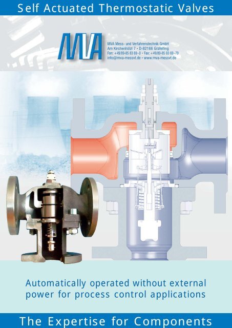
Self Actuated Thermostatic Valves<br />
<strong>MVA</strong> <strong>Mess</strong>- und Verfahrenstechnik GmbH<br />
Am Kirchenhölzl 7 • D-82166 Gräfelfing<br />
Fon: +49/89-85 83 69-0 • Fax: +49/89-85 83 69-70<br />
info@mva-messvt.de • www.mva-messvt.de<br />
Automatically operated without external<br />
power for process control applications<br />
The Expertise for Components
SELF ACTUATED THERMOSTATIC VALVES<br />
Temperature regulation of lubrication<br />
and cooling loops with oil<br />
or water and solar systems for<br />
the following applications<br />
<strong>MVA</strong> offers a wide range of automatically operated<br />
thermostatic control valves for mixing and<br />
bypass loops. All valves are equipped with fully<br />
automatic working elements based on the wax<br />
expansion principle and provide most reliable<br />
and approved components for process control<br />
applications since decades.<br />
Applications:<br />
● Compressors<br />
● Diesel engines<br />
● Gearboxes<br />
● Steam turbines<br />
● Gas turbines<br />
● Refrigeration<br />
systems<br />
● Solar systems<br />
Sizes:<br />
DN 20 - 40<br />
Threaded Connections<br />
3/4” - 1 1/2”<br />
DN 20 - 150<br />
Flanges according<br />
to DIN or ANSI<br />
Flowrates:<br />
2 to 320 m 3 /h<br />
Body Material:<br />
Cast Iron, Graphite Iron,<br />
Cast Steel, Aluminium,<br />
Bronce, Stainless Steel<br />
Nominal Temperatures:<br />
+13 °C bis +116 °C<br />
Special Features:<br />
Kanigen Plated Elements,<br />
PTFE Sealings,<br />
Manual Override<br />
<strong>MVA</strong> • Am Kirchenhölzl 7 • D-82166 Gräfelfing • Fon: +49/89-85 83 69 -0 • Fax: +49/89-85 83 69 -70 • info@mva-messvt.de • www.mva-messvt.de<br />
2
GENERAL INFORMATION -THERMOSTATIC VALVES ...<br />
<strong>MVA</strong> Thermostatic Valves are used to provide reliable,<br />
automatic control of fluid temperatures in turbines,<br />
compressors and engine water jacket and lubricating<br />
oil cooling systems. They are also suitable for<br />
process control and industrial applications where<br />
fluids must be mixed or diverted depending on their<br />
temperatures. They may also be applied to cogeneration<br />
systems to control temperatures in the<br />
heat recovery loop assuring proper engine cooling<br />
and maximising heat recovery.<br />
All <strong>MVA</strong> Thermostatic Valves are equipped with<br />
positive 3-way valve action in which the water or<br />
lubricating oil is positively made to flow in the direction<br />
required. On jacket water applications when the<br />
engine is started up and is cold, the <strong>MVA</strong> Thermostatic<br />
Valve causes all of the water to be positively<br />
by-passed back into the engine, thus providing the<br />
quickest warm-up period possible. After warm up,<br />
the correct amount of water is by-passed and automatically<br />
mixed with the cold water returning from<br />
the heat exchanger or other cooling device to produce<br />
the desired jacket water outlet temperature. If<br />
ever required, the <strong>MVA</strong> Thermostatic Valve will shut<br />
off positively on the by-pass line for maximum<br />
cooling. The 3-way action of the <strong>MVA</strong> Thermostatic<br />
Valve allows a constant volume of water through the<br />
pump and engine at all times with no pump restriction<br />
when the engine is cold.<br />
ADJUSTMENTS & MAINTENANCE<br />
No adjustments are ever required on <strong>MVA</strong> Thermostatic<br />
Valves. Once installed a <strong>MVA</strong> Thermostatic<br />
Valve will provide years of trouble-free service.<br />
TEMPERATURE SETTINGS<br />
Because <strong>MVA</strong> Thermostatic Valves are set to a predetermined<br />
temperature at the factory, costly errors<br />
due to mistakes of operating personnel are eliminated.<br />
After a <strong>MVA</strong> Thermostatic Valve has been<br />
installed, it is impossible for the operator to arbitrarily<br />
change the operating temperature and run the<br />
engine too cold or too hot unless the temperature<br />
element assemblies themselves are changed.<br />
<strong>MVA</strong> Thermostatic Valves are temperature rated for<br />
the expected nominal operating temperature in jakket<br />
water service. On lubricating oil applications the<br />
system operating temperature may be slightly<br />
above the nominal rating, depending on the type of<br />
oil flow rate, oil cooler capacity and other conditions<br />
of the system.<br />
For long life, <strong>MVA</strong> Thermostatic Valves should not<br />
be operated continuously at temperatures more<br />
than about 54° F (12°C) above their nominal ratings.<br />
If higher continuous over-temperatures are expected,<br />
contact the factory for recommendations.<br />
OPERATION<br />
The power creating medium utilises the expansion<br />
of a special thermostatic wax material which<br />
remains in a semi-solid form and which is highly<br />
sensitive to temperature changes.<br />
INSTRUCTIONS FOR <strong>MVA</strong> TEMPERATURE VALVE<br />
MODEL "M" WITH AND WITHOUT MANUAL OVER-<br />
RIDE<br />
1) Maintenance<br />
Properly applied and installed, <strong>MVA</strong> Thermostatic<br />
Valves require minimal maintenance. An inspection<br />
at 2 or 3 year intervals is adequate to detect and<br />
make provision for manual wear.<br />
Excessive temperatures, chemical, electrolytic attack<br />
or cavitation will shorten the life of the element<br />
assemblies, seals and seats. These items are replaceable.<br />
Water additives may cause swelling of the<br />
O-ring seals around the stem and the sliding valve<br />
to a point where they may affect valve action and<br />
require replacement. Synthetic base lubricants will<br />
definitely attack the O-ring seals which may be<br />
replaced by O-rings of alternate materials. Contact<br />
the <strong>MVA</strong> factory for recommendations.<br />
Carbonates, scale and other solids must not be<br />
permitted to build up on sliding valve or sensing<br />
cup surfaces. The valve and element assemblies<br />
may be cleaned with mild acid or Oakite solutions.<br />
Hard scale may require wire brush buffing.<br />
<strong>MVA</strong> • Am Kirchenhölzl 7 • D-82166 Gräfelfing • Fon: +49/89-85 83 69 -0 • Fax: +49/89-85 83 69 -70 • info@mva-messvt.de • www.mva-messvt.de<br />
3
GENERAL INFORMATION -THERMOSTATIC VALVES ...<br />
2) Manual override<br />
If for any reason "M"-Thermostatic valves with<br />
manual override should not work properly, each element<br />
assembly is fitted with an infinitaly variable<br />
override which allows on accurate manual temperature<br />
regulation.<br />
Before the manual override is used we recommend,<br />
however, to check whether the cause of trouble is<br />
not somewhere in the system, according to paragraph<br />
3) "Trouble shooting". Manual override should<br />
only be used in emergency case.<br />
If a thermostatic valve with several element assemblies<br />
is installed (DN 65 - DN 125) it is recommended<br />
to open one element assembly after the other<br />
against cooler by turning screw until desired temperature<br />
is nearly reached. Final regulation is done<br />
with next element assembly.<br />
3) Trouble-Shooting<br />
In the event that your cooling system does not operate<br />
close to the desired temperature, the following<br />
check list may point to one or more causes for the<br />
problem.<br />
3.1 System Temperature too cold<br />
a) Insufficient heat rejected to coolant to maintain<br />
the temperature<br />
b) Wrong nominal temperature selected<br />
c) Thermostatic valve is greatly oversized for the<br />
system flow rate or cooling capacity of the<br />
system is much greater than is required<br />
d) Thermostatic valve ist installed backwards, forces<br />
water to cooler and causes engine to run<br />
cold under all conditions<br />
e) Worn O-ring seal around the element assembly<br />
f) Too great a pressure difference (in excess 1,7<br />
bar) between ports 2 and 3<br />
g) Foreign material is stuck between sliding valve<br />
and seat<br />
h) Element assembly may have been over-temperated<br />
sufficiently to affect calibration or rupture wax<br />
seal and does therefore not close "2"-port completely<br />
anymore. Requires complete new element<br />
assembly.<br />
3.2 System Temperature too hot<br />
a) Cooling capacity of system not adequate<br />
b) Thermostatic valve too small for flow rate (also<br />
causes high pressure drop and possibly cavitation)<br />
c) Valve installed backwards; as temperature<br />
increases, Port 2 closes, reducing flow to cooler<br />
d) Bypass will not close due to worn or pitted seats,<br />
sliding valve, O-ring seal, etc.<br />
e) Worn O-ring seal around the element assembly<br />
f) Element assembly may have been over temperated<br />
sufficiently to affect calibration or rupture wax<br />
seal and does therefore not fully open "3"-port<br />
anymore. Requires complete new element<br />
assembly.<br />
g) Solids build up on sliding valve prevents proper<br />
action of element assembly<br />
h) Foreign material stuck between sliding valve and<br />
seat<br />
i) Excessive pressure differential between port<br />
(very low pressure through bypass leg, very high<br />
pressure in cooler)<br />
3.3 Additional Considerations<br />
a) Thermometers: A thermometer that reads the<br />
same whether system is cold or hot needs replacing<br />
b) Location of thermometers: on horizontal pipe<br />
runs, these should be in the side of the pipe when<br />
possible, particularly on oil systems. Also, pipes<br />
do not always run full so the thermometer may<br />
not be immersed in the fluid<br />
c) Thermometers should be as far as possible<br />
downstream from the confluence of two streams<br />
of different temperature to allow complete mixing<br />
d) Look for bypasses or "sneak circuits" which prevent<br />
thermostatic valve control of the complete<br />
system<br />
<strong>MVA</strong> • Am Kirchenhölzl 7 • D-82166 Gräfelfing • Fon: +49/89-85 83 69 -0 • Fax: +49/89-85 83 69 -70 • info@mva-messvt.de • www.mva-messvt.de<br />
4
GENERAL INFORMATION -THERMOSTATIC VALVES ...<br />
Fig. 1 COOLING WATER-HEAT<br />
EXCHANGER<br />
This scheme shows the cooling<br />
water circuit of a fix installed or a<br />
ship engine with cooling by a heat<br />
exchanger. The <strong>MVA</strong> Thermostatic<br />
Valve is in such a way installed, that<br />
the temperature of the cooling water<br />
at the outlet of the engine will be<br />
maintained constant. Should exist<br />
any problem cause by enclosed air,<br />
a narrow ventilation pipe (x) leading<br />
from the highest point of the system<br />
to the compensation tank will help.<br />
Fig. 2 COOLING WATER–AIR<br />
COOLING DEVICE<br />
This arrangement is used practically<br />
always in vehicles and fixed installed<br />
engines with air cooling device.<br />
Here, the temperature of the cooling<br />
water also will be maintained constant<br />
at the outlet of the engine.<br />
Fig. 3 COOLING WATER –<br />
DIRECT COOLING<br />
Today, small and medium size engines<br />
are partially still cooled directly<br />
by sea water, although the disadvantages<br />
of such systems are well<br />
known.<br />
In Fig. 3 the temperature of the cooling<br />
water is maintained constant at<br />
the engine’s outlet. If the point T is<br />
above the water line, a non-returnvalve<br />
(W) must be installed, in order<br />
to avoid that the cooling system<br />
looses all its fluid if the engine is<br />
stopped.<br />
<strong>MVA</strong> • Am Kirchenhölzl 7 • D-82166 Gräfelfing • Fon: +49/89-85 83 69 -0 • Fax: +49/89-85 83 69 -70 • info@mva-messvt.de • www.mva-messvt.de<br />
5
GENERAL INFORMATION -THERMOSTATIC VALVES ...<br />
Fig 4 COOLING WATER<br />
CONTROL BY MIXING<br />
Contrary to the system shown in Fig.<br />
1 cold and warm water are mixed and<br />
the temperature will be maintained<br />
constant at the inlet of the engine. X<br />
serves, if necessary, for ventilation of<br />
the system. Another possibility for<br />
this kind of control is shown in Fig. 6<br />
Fig. 5 LUBRICATION OIL<br />
CONTROL BY SHORT- CIRCUIT<br />
(DIVERTING)<br />
In this scheme the <strong>MVA</strong> Thermostatic<br />
Valve is located in the lubrication<br />
oil circuit as a short- circuit controller.<br />
Similar as in Fig. 1 the temperature<br />
of the cooling water, in this<br />
scheme the temperature of the oil,<br />
that means the temperature of the oil<br />
at the outlet of the engine is maintained<br />
constant.<br />
Fig. 6 LUBRICATION OIL CON-<br />
TROL BY MIXING<br />
In this system the <strong>MVA</strong> Thermostatic<br />
Valve mixes the warm oil coming<br />
from the engine with the cold one<br />
coming from the cooling device.<br />
This assures, that the temperature of<br />
the oil flow to the bearings, that<br />
means the temperature of the oil at<br />
the inlet of the engine will be maintained<br />
constant.<br />
<strong>MVA</strong> • Am Kirchenhölzl 7 • D-82166 Gräfelfing • Fon: +49/89-85 83 69 -0 • Fax: +49/89-85 83 69 -70 • info@mva-messvt.de • www.mva-messvt.de<br />
6
CODE FOR THE MODELS M20 ... M40<br />
Subject to change without prior notice, issue Sept. 2007<br />
<strong>MVA</strong> • Am Kirchenhölzl 7 • D-82166 Gräfelfing • Fon: +49/89-85 83 69-0 • Fax: +49/89-85 83 69-70 • info@mva-messvt.de • www.mva-messvt.de<br />
7
TECHNICAL DATA MODELS M20 ... M40<br />
For the purpose of design engineering deviation of<br />
up to 10 mm should be respected. (Exact values on<br />
demand)<br />
Subject to change without prior notice, issue Sept. 2007<br />
<strong>MVA</strong> • Am Kirchenhölzl 7 • D-82166 Gräfelfing • Fon: +49/89-85 83 69-0 • Fax: +49/89-85 83 69-70 • info@mva-messvt.de • www.mva-messvt.de<br />
8
CODE FOR THE MODELS M50 ... M150<br />
Subject to change without prior notice, issue Sept. 2007<br />
<strong>MVA</strong> • Am Kirchenhölzl 7 • D-82166 Gräfelfing • Fon: +49/89-85 83 69-0 • Fax: +49/89-85 83 69-70 • info@mva-messvt.de • www.mva-messvt.de<br />
9
TECHNICAL DATA MODELS M50 ... M150<br />
For the purpose of design engineering deviation of<br />
up to 10 mm should be respected. (Exact values on<br />
demand)<br />
Subject to change without prior notice, issue Sept. 2007<br />
<strong>MVA</strong> • Am Kirchenhölzl 7 • D-82166 Gräfelfing • Fon: +49/89-85 83 69-0 • Fax: +49/89-85 83 69-70 • info@mva-messvt.de • www.mva-messvt.de<br />
10