Hy Supply Unit - MVA Mess
Hy Supply Unit - MVA Mess
Hy Supply Unit - MVA Mess

You also want an ePaper? Increase the reach of your titles
YUMPU automatically turns print PDFs into web optimized ePapers that Google loves.
<strong>MVA</strong><br />
<strong>Mess</strong>- und<br />
VerfahrensTechnik<br />
GmbH<br />
Am KirchenHölzl 7<br />
D-82166 Gräfelfing/München<br />
Fon +49-89-8583 69-0<br />
Fax +49-89-8583 69-70<br />
Seite 1 von 12 C:\Eigene<br />
Dateien\Texte\Manuals\HYmanu\VBHengl1105.doc<br />
eMail<br />
info@mva-messvt.de<br />
interNet<br />
www.mva-messvt.de<br />
Ölhydraulik-Versorgungseinheiten<br />
für Ventilantriebe<br />
<strong>Hy</strong>draulic-<strong>Supply</strong>-<strong>Unit</strong>s<br />
for valve actuators<br />
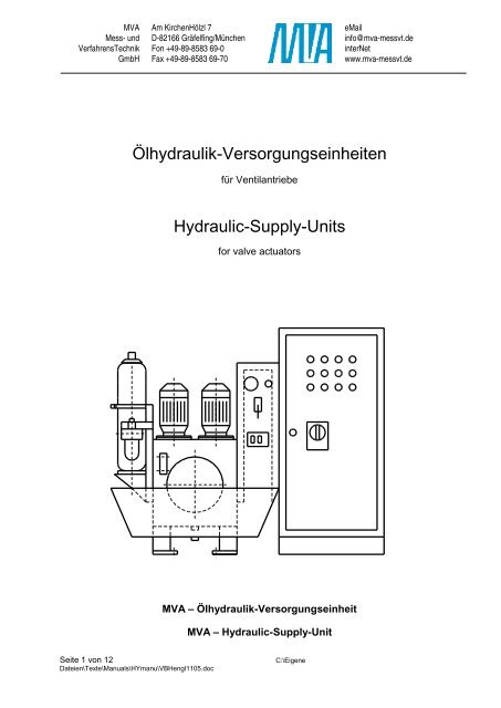
<strong>MVA</strong> – Ölhydraulik-Versorgungseinheit<br />
<strong>MVA</strong> – <strong>Hy</strong>draulic-<strong>Supply</strong>-<strong>Unit</strong>
<strong>MVA</strong><br />
<strong>Mess</strong>- und<br />
VerfahrensTechnik<br />
GmbH<br />
Am KirchenHölzl 7<br />
D-82166 Gräfelfing/München<br />
Fon +49-89-8583 69-0<br />
Fax +49-89-8583 69-70<br />
1. Description<br />
Inhaltsverzeichnis<br />
Table of contents<br />
Seite 2 von 12 C:\Eigene<br />
Dateien\Texte\Manuals\HYmanu\VBHengl1105.doc<br />
eMail<br />
info@mva-messvt.de<br />
interNet<br />
www.mva-messvt.de<br />
2. Calculation Data Sheet for <strong>Hy</strong>draulic <strong>Unit</strong>s and Actuators<br />
3. Technical Data for HHS2.... Series<br />
4. Technical Data for <strong>Hy</strong>draulic Actuators<br />
5. Instructions for Installation, Operation and Maintenance for <strong>Hy</strong>-Actuators
<strong>MVA</strong><br />
<strong>Mess</strong>- und<br />
VerfahrensTechnik<br />
GmbH<br />
Am KirchenHölzl 7<br />
D-82166 Gräfelfing/München<br />
Fon +49-89-8583 69-0<br />
Fax +49-89-8583 69-70<br />
<strong>MVA</strong> - OIL HYDRAULIC SUPPLY UNIT<br />
Seite 3 von 12 C:\Eigene<br />
Dateien\Texte\Manuals\HYmanu\VBHengl1105.doc<br />
eMail<br />
info@mva-messvt.de<br />
interNet<br />
www.mva-messvt.de<br />
1. SUPPLY CONCEPT: The most simply - built valve actuators are hydraulic jacks. With suitablyselected oil<br />
pressures, they can be kept small and cheap, while delivering large forces and high power. In most<br />
applications, these actuators are mounted in groups, which are also supplied together. Group supply allows<br />
for effective and genuine redundancy with simple means.<br />
The majority of valves in a modern power plant either are not in a continuous control operation or they only<br />
make large control movements when there is a failure, which means rarely. The average power demand<br />
generally lies well below peak demand. For these operating conditions, peak demand is satisfied from an<br />
accumulator, which means that the pump is not sized to satisfy peak power demand. This lowers investment<br />
- and operating costs.<br />
While oil pressure considerably influences cost of large, powerful actuators, it is not the case for small<br />
actuators. Small supply systems requiring pumps are also for high pressure applications. This is in contrast<br />
to the last 10 to 20 years, which justify the jump to high pressure pumps in this time.<br />
2. ACCUMULATOR CHARGING: The ON/OFF operation is the charging mode with motor stoppage times<br />
of 5 to 15 minutes. A mechanical reservoir charging valve is incorporated in the small units, which switches<br />
the pump to the zero pressure cycle, but not for redundant supply units.<br />
3. POWER STEPS: A power step jump of 1.6 is appropriate and provides sufficient flexibility in the design.<br />
(A jump by the factor of 2 has proven to be too coarse.) In the following, hydraulic fluid flow in liters/minute<br />
is introduced as a type designation, followed by the nominal accumulator size (e.g. HHS2-20-30).<br />
4. ACCUMULATOR SIZES: Long - life bubble accumulators are proven in operation, as are diaphragm<br />
accumulators for smaller volumes. Accumulator size is determined by the ratio of peak power to average<br />
power, but it can also be influenced by safety considerations. The charging ratio is usually selected to be 1.2<br />
.... 1.4.<br />
5. PRESSURE CONTROL FOR THE SYSTEM SUPPLIED: Pressure control prevents deviations of the<br />
drive's running speed to get too large. When the accumulator /charging ratio is 1.2 ... 1.4, pressure control<br />
is not used, because pressure induced speed deviations remain within +/- 5 % ... +/10 %. <strong>Unit</strong>s for power<br />
plants are therefore delivered without pressure control.<br />
6. SIZING THE CONTAINER: The container volume (gross tank volume) is comprised of the minimum oil<br />
volume, the floating volume (out of reservoir and pipe) as well as the air volume (or the volume of installed<br />
equipment, respectively). Container size is therefore, to some extent, determined by the presence of a<br />
reservoir. It is sized economically (= small), it offers sufficient cooling area, provides enough oil capacity and<br />
ensures a long service life without oil changes.<br />
7. SELECTING PUMP TYPES: Long - duration laboratory tests of different types of pumps in the typical<br />
operating modes of such hydraulic units showed that, in the pressure region from 100 - 200 bar, aside from<br />
piston pumps (axial or radial), only certain heavy duty gear pumps achieve a service life which is acceptable<br />
in power plants. This good gear pumps are employed for power plants in the last 10 years up to 250 bar.<br />
8. MOTORS TYPES AND SIZES: control systens are running Motors for pump systems with reservoir<br />
charging have the following operational characteristics: they never start at full load, normally at half or 3/4<br />
load. Power demand increases continuously until switch - off or load relief in the idle mode. Heat stress is<br />
much smaller than at rated power of the motor. No masses have to be accelerated. Overloading of the motor<br />
occurs only when the charger fails at high pressure. In this case, the motor is switched off by its own<br />
protection. If it is oversized in terms of power, it will not do that. Such motors are designed with narrow<br />
margins, which lowers heat stress during start - up (as well as cost).The motors, generally four - poled three<br />
phase motors, are of the closed design, with exterior blower, protection type DIN 40050 - IP54, insulation<br />
class F (or equivalent).
<strong>MVA</strong><br />
<strong>Mess</strong>- und<br />
VerfahrensTechnik<br />
GmbH<br />
Am KirchenHölzl 7<br />
D-82166 Gräfelfing/München<br />
Fon +49-89-8583 69-0<br />
Fax +49-89-8583 69-70<br />
Seite 4 von 12 C:\Eigene<br />
Dateien\Texte\Manuals\HYmanu\VBHengl1105.doc<br />
eMail<br />
info@mva-messvt.de<br />
interNet<br />
www.mva-messvt.de<br />
9. TWO MODEL RANGES: Sizes from 2 to 6 liters/minute are used in industry, while types from 8 to 50<br />
liters/minute are for power plant applications. Both model ranges are also used in other kinds of hydraulic<br />
applications, i.e. machine tools, presses, hydraulic hoisting machinery etc.<br />
10. DATA FOR HYDRAULIC - SUPPLY UNITS<br />
10.1 BASIC DATA, OVERVIEW<br />
Gradation of hydraulic fluid flow Qv = 2 ... 50 l/min<br />
(Gradation 1.4…1.6 x)<br />
Tank gross volume<br />
with one pump Vt = 5 * qv l (
<strong>MVA</strong><br />
<strong>Mess</strong>- und<br />
VerfahrensTechnik<br />
GmbH<br />
Am KirchenHölzl 7<br />
D-82166 Gräfelfing/München<br />
Fon +49-89-8583 69-0<br />
Fax +49-89-8583 69-70<br />
11.2 INPUTS TO MOTOR CONTROL AND MONITORING:<br />
11.21 INPUTS FROM THE OWN HYDRAULIC UNIT:<br />
Seite 5 von 12 C:\Eigene<br />
Dateien\Texte\Manuals\HYmanu\VBHengl1105.doc<br />
eMail<br />
info@mva-messvt.de<br />
interNet<br />
www.mva-messvt.de<br />
PAL Pressure to low – Alarm WARNING<br />
If another HY-units not o.k. then ALARM, locking<br />
actuators<br />
PLL Pressure to low motor ON, WARNING<br />
If another HY-units not o.k. then ALARM, locking<br />
actuators<br />
PL Pressure low motor ON<br />
PH Pressure high motor OFF<br />
PHH Pressure to high motor OFF, WARNING<br />
OPTIONS: NLL LEVEL OIL to low motor OFF, WARNING<br />
If another HY-units not o. k. then ALARM, locking<br />
actuators<br />
THH Temperature to high motor OFF, WARNING<br />
If another HY-units not o. k. then ALARM, locking<br />
actuators<br />
11.22 MANUAL INPUTS:<br />
ON not locking motor ON, pressure limits are not in<br />
order<br />
AUTO locking logic and control systems are running<br />
11.23 INTERNAL DECISION:<br />
MOTOR RUNS AGAIN AND AGAIN time more than 10 to 20 minutes<br />
WARNING<br />
11.24 OUTPUTS:<br />
M1, M2 motor ON/OFF pump motors on and off with rellay<br />
WA WARNING fault – control systens are running<br />
AL ALARM manual and automatic systems<br />
default, only safety direction are possible<br />
OPTION: M.A.D. all actuator systems are locked<br />
12. CONNECTING HYDRAULIC- AND PUMP-UNITS: If there is more than one pump unit installed for<br />
redundant reasons, so there are two units connected with one common tank. For service with two pumps<br />
are systems with one or two separated tanks suited, the difference is the internal circuit system.<br />
DATA SHEET FOR HYDRAULIC UNIT<br />
1 Project: Proj. ABB Meliti Achlada HDU - <strong>MVA</strong> No. 0805.99 and NDU for example<br />
2 Item no.: I II III<br />
3 kks code: MAN10 LCE10 LBH20<br />
4 HYDRAULIC ACTUATOR: AH200/80-80FO AH100/50-45 AH100/50-35
<strong>MVA</strong><br />
<strong>Mess</strong>- und<br />
VerfahrensTechnik<br />
GmbH<br />
Am KirchenHölzl 7<br />
D-82166 Gräfelfing/München<br />
Fon +49-89-8583 69-0<br />
Fax +49-89-8583 69-70<br />
Seite 6 von 12 C:\Eigene<br />
Dateien\Texte\Manuals\HYmanu\VBHengl1105.doc<br />
eMail<br />
info@mva-messvt.de<br />
interNet<br />
www.mva-messvt.de<br />
5 nos.: ./. 2 2 1<br />
6 oil supply min. bar 130 130 130<br />
7 piston diameter mm 200 100 100<br />
8 stem diameter mm 80 50 50<br />
9 effective stroke mm 70 40 30<br />
10 stroke max. mm 80 45 35<br />
11 actuating time control s 20 20 ./.<br />
12 actuating time QO
43<br />
<strong>MVA</strong><br />
<strong>Mess</strong>- und<br />
VerfahrensTechnik<br />
GmbH<br />
Am KirchenHölzl 7<br />
D-82166 Gräfelfing/München<br />
Fon +49-89-8583 69-0<br />
Fax +49-89-8583 69-70<br />
Seite 7 von 12 C:\Eigene<br />
Dateien\Texte\Manuals\HYmanu\VBHengl1105.doc<br />
eMail<br />
info@mva-messvt.de<br />
interNet<br />
www.mva-messvt.de<br />
44 REFERENCES ABOUT DESIGN AND OPERATION<br />
45<br />
The calculation and the design of the actuators and the hydraulic units are according to DIN<br />
46 and "AD-Merkblätter".<br />
47 All pressures are in bar g.<br />
48 Please check all datas!<br />
49<br />
FOo = actuator force - stem retracting, in position<br />
50 Explanation:<br />
stem retracted<br />
FOc = actuator force - stem retracting, in position<br />
51<br />
stem extended<br />
FCo = actuator force - stem extending, in position<br />
52<br />
stem retracted<br />
FCc = actuator force - stem extending, in position<br />
53<br />
stem extended<br />
HY = actuator force result from oil pressure and<br />
54<br />
spring force<br />
55 S = spring force of the actuator<br />
56<br />
57<br />
58<br />
59 The calculation of the developed force (thrust) for the actuator is given by the customer.<br />
60<br />
61 Revision 0, date 06.10.00
<strong>MVA</strong><br />
<strong>Mess</strong>- und<br />
VerfahrensTechnik<br />
GmbH<br />
Series denomination:<br />
Am KirchenHölzl 7<br />
D-82166 Gräfelfing/München<br />
Fon +49-89-8583 69-0<br />
Fax +49-89-8583 69-70<br />
Technical Data <strong>MVA</strong> <strong>Hy</strong>draulic <strong>Unit</strong>s<br />
Series HHS...<br />
HHS 2 - 12 - 35 – 400/50 .... more descriptions with text<br />
| | | | | |<br />
| | | | | |<br />
| | | | | |___ freqenzy<br />
| | | | |<br />
| | | | |______ power supply<br />
| | | |<br />
| | | |__________ nom. volume accumulator<br />
| | |<br />
| | |______________ nom. flow pump (one number)<br />
| |<br />
| |__________________ number of pumps<br />
|<br />
|_____________________ series high pressure<br />
Seite 8 von 12 C:\Eigene<br />
Dateien\Texte\Manuals\HYmanu\VBHengl1105.doc<br />
eMail<br />
info@mva-messvt.de<br />
interNet<br />
www.mva-messvt.de<br />
Typen/series Qv Pr Pl Ph Pk Vt VÖ VP Nmot Fl Fa Fp P,T Vs W<br />
HHS 2 - 6 2 x 6 180 180 210 250 100 63 10 2 x 3 10 60 10 16 10 420<br />
HHS 2 - 8 2 x 8 180 180 210 250 100 63 20 2 x 4 10 60 10 16 20 450<br />
HHS 2 - 12 2 x 12 180 180 210 250 100 63 20 2 x 7,5 10 60 10 20 20 510<br />
HHS 2 - 20 2 x 20 180 180 210 250 160 100 35 2 x 11 10 60 10 25 20 580<br />
HHS 2 - 32 2 x 32 180 180 210 250 250 160 50 2 x 15 10 60 10 32 35 650<br />
HHS 2 - 50 2 x 50 180 180 210 250 400 250 85 2 x 22 10 60 10 40 50 760<br />
Qv [l/min] nom. flow of one pump with 4-pole Vp [l] floating volume oil<br />
motor and 50 Hz<br />
Nmot [kW] nom. power rating motor<br />
Pr [bar] Highest pressure after control valve, Fl [µm] air filter retention<br />
if available<br />
Fa [µm] suction filter retention<br />
Pl [bar] start of accumulator charging Fp [µm] main flow pressure retention<br />
Ph [bar] switch off accumulator charging P,T [mm] diameter connections DN<br />
Pk [bar] Design pressure Vs [l] nom. volume accumulator<br />
available 10, 20, 35, 50 l<br />
Vt [l] nom. volume tank<br />
VÖ [l] volume oil W [kg] wight without control cabinet
<strong>MVA</strong><br />
<strong>Mess</strong>- und<br />
VerfahrensTechnik<br />
GmbH<br />
Am KirchenHölzl 7<br />
D-82166 Gräfelfing/München<br />
Fon +49-89-8583 69-0<br />
Fax +49-89-8583 69-70<br />
Technical Data <strong>MVA</strong> <strong>Hy</strong>draulic Actuator<br />
Series AH….<br />
Seite 9 von 12 C:\Eigene<br />
Dateien\Texte\Manuals\HYmanu\VBHengl1105.doc<br />
eMail<br />
info@mva-messvt.de<br />
interNet<br />
www.mva-messvt.de<br />
Type denomination: AHFS.C.200/80-120.900.60/80 __ dimensions and forces disc spring<br />
| | | | | I<br />
| | | | | I______________ max. stroke<br />
| | | | I<br />
| | | | I_________________ diameter piston rod<br />
| | | I<br />
| | | I____________________ diameter piston<br />
| | I<br />
| | I________________________ C = with positioner, O = without positioner<br />
| I<br />
I I__________________________ FS = spring closing, FO = spring opening<br />
I DA = duple acting<br />
I_____________________________ series<br />
Standards: The mounting dimensions and types of attachment of the cylinders are in conformity with the<br />
<strong>MVA</strong>-Standard or the indicated DIN and ISO Standards.<br />
Pressures: Nominal pressure PN 250<br />
Operating pressure PB 210<br />
Test pressure, statical 325 all pressures in bar<br />
The actuators are designed for controlled operation, oriented at the VDE 0530 or ICE 34 standard, that<br />
means for an operation with 25% ED.<br />
The piston rods, bearing surfaces and seal elements resist to extreme shock loads and load cycles. The do<br />
not require any maintenance. All seals are designed for pressures up to 400 bar.<br />
Installation position: The installation position is at will and is determined by the installation position of the<br />
valve. For mounting on the valve and taking into operation the operating instructions must be respected.<br />
Pressure fluid: Mineral oil according to DIN 51524 and 51525, others upon request; Temperature –30 to<br />
+80 °C, higher temperatures require different seals; Viscosity approx. (30 to 80)*10^6 m²/s equivalent to<br />
approx. 4,3 to 11°E at +50°C. A maximum grade of contamination according to ISO 4406 class 19/16 or<br />
NAS 1638 class 10 should not be exceeded.<br />
Structure of the Standard <strong>Hy</strong>draulic Cylinder: The cylinders are delivered as robust welded/screw<br />
structure with honed, seamless tubes (roughness of the inner surface max. 0,5 µm) and with hardened and<br />
subsequently tempered, polished, dimensioned-hard-chromium-plated piston rods (surface roughness max.<br />
2 µm), thickness of the chromium layer 25 +/- 5 µm. The cylinders were provided with pressure fluid by the<br />
attached magnetic valve assembly. The connections are in conformity with the standards DIN 2353 for<br />
threaded pipe fittings with pipe thread of Whitworth form; the dimension is determined by the dimension of<br />
the cylinder. The connections of the piston rods are realized upon the customers request.<br />
The dimensions for installation and integration without indication of tolerances are according to DIN<br />
7168mT. Eventually installed disc springs are calculated and dimensioned for 100.000 load cycles with<br />
sufficient power reserve in case of a break of one spring.<br />
Delivery status: The cylinders are delivered without fluid, provided with an one-layer transport protection<br />
coating Percotex LA-wash primer, a two component product on a polyacryl basis a with low solvent<br />
content, chromatic value black, layer thickness approx. 25 µm.<br />
Each cylinder will be tested individually according to <strong>MVA</strong> standards; acceptance tests according to<br />
customers standards as an option.
<strong>MVA</strong><br />
<strong>Mess</strong>- und<br />
VerfahrensTechnik<br />
GmbH<br />
Am KirchenHölzl 7<br />
D-82166 Gräfelfing/München<br />
Fon +49-89-8583 69-0<br />
Fax +49-89-8583 69-70<br />
Seite 10 von 12 C:\Eigene<br />
Dateien\Texte\Manuals\HYmanu\VBHengl1105.doc<br />
eMail<br />
info@mva-messvt.de<br />
interNet<br />
www.mva-messvt.de<br />
Instructions for Installation, Operation and Maintenance<br />
for <strong>MVA</strong> – <strong>Hy</strong>draulic Actuators<br />
W A R N I N G<br />
Improper installation-, operation- and maintenance work might cause heavy accidents. Therefore these<br />
works should only be done by experienced specialized persons. The guide lines of the suppliers, especially<br />
of the suppliers of the hydraulic fluids must be respected.<br />
General<br />
Before installation and taking into operation of the hydraulic cylinders the advice of the following documents<br />
must be taken into account: attached drawings, hydraulic – and electrical diagrams, -DIN 51524/51525<br />
<strong>Hy</strong>draulic fluids.<br />
Installation<br />
Before starting installation the completeness of all installation parts and auxiliary materials must be<br />
controlled. Also transport damages must be considered. Before installing the hydraulic cylinder the type<br />
denomination of the hydraulic cylinder should be compared with the data of the order. During the installation<br />
of the cylinder for cleanliness of the working area must be taken care.<br />
Tubes, especially after their cutting and containers must be cleaned from cinder, filings and other<br />
contaminations before installing them. Hot curved or welded tubes must be acid cleaned, washed and oiled.<br />
Sealing materials like hemp, cement, silicon or sealing tape must not be used in any case, because said<br />
materials among others may cause contamination and thus produce system malfunction. For cleaning<br />
purposes only use tissues which do not loose fibers or special paper. Using lifting devices use the soft side<br />
and/or the transport devices. For installation and in order to hold on the piston rod hock wrenches with<br />
round finger according to DIN 1810 are required. The fixing screws must be tightened homogeneous and if<br />
required with the indicated torque.<br />
Installation position<br />
At will. <strong>Hy</strong>draulic cylinders must not be installed preloaded. It must be considered that the attachments of<br />
the cylinder and the piston rod are shaped and adjusted in such a way (they must be in alignment), that<br />
during operation no side forces or bending forces act on the piston rod. If so, damages of the hydraulic<br />
cylinder may occur and the manufacturers liability will be terminated.<br />
Pressure connections<br />
The pressure connections in the mounted solenoid valve manifold are designed for connection screw usual<br />
in trade. In order to avoid leakages the installation advices of the connecting screw manufacturers must be<br />
observed. The correct laying of the flexible lines must be respected. Rubbing and pushing of the flexible<br />
lines must be avoided.<br />
Electrical connections<br />
The connections of position transmitters, inductive or mechanical limit switches, etc. must be taken from<br />
the respective installation guide lines.<br />
Preparation for taking into operation<br />
Before the real action of taking into operation of the hydraulic cylinder the following general controls beside<br />
the system specific checks should be realized:<br />
- General visual check regarding damages, contamination and completeness.<br />
- Are all pipes and flexible hoses properly installed and cleaned?<br />
- Are the hydraulic and electrical connections correctly installed?<br />
- Are eventually existing position transmitters, inductive or mech. limit switches<br />
correctly installed and adjusted?<br />
- Are all screw connections and flanges tightened?<br />
- Is the cylinder without preloading and in alignment?
<strong>MVA</strong><br />
<strong>Mess</strong>- und<br />
VerfahrensTechnik<br />
GmbH<br />
Am KirchenHölzl 7<br />
D-82166 Gräfelfing/München<br />
Fon +49-89-8583 69-0<br />
Fax +49-89-8583 69-70<br />
- Are all tools, auxiliary materials, arresting and cleaning devices removed?<br />
- Has the cylinder the necessary space for a free and proper movement<br />
- Is the system filled up with the required fluid up to the upper oil level mark?<br />
Seite 11 von 12 C:\Eigene<br />
Dateien\Texte\Manuals\HYmanu\VBHengl1105.doc<br />
eMail<br />
info@mva-messvt.de<br />
interNet<br />
www.mva-messvt.de<br />
After the control the installation was completely and properly done, the putting into operation may be done.<br />
Putting into operation<br />
In order to avoid injuries, hydraulic cylinders should be put into operation only if installed or fixed to special<br />
jigs, - especially if a disc spring is built in - because the extending and retracting piston rod might<br />
present a danger for injuries. For safety reasons in the putting into operation activities only the directly<br />
involved persons should be present in situ. If required the dangerous area should be protected by protecting<br />
grids or similar devices.<br />
Due to the fact that these instructions only refer to the hydraulic cylinder(s) and the missing of the detailed<br />
information regarding the complete system, the operating manual of the complete system is valid for the<br />
putting into operation of the complete system and must be respected.<br />
Pressure Fluid<br />
Please control if the pressure fluid of the system is in conformity with the required pressure fluid of the<br />
hydraulic cylinder. Please respect the recommendations of the cylinder manufacturers or the data sheet.<br />
The cautious selection of tested and approved hydraulic fluids is prerequisite for an optimal function of the<br />
hydraulic system. Generally mineral fluids HL or better HLP according to DIN 51524 or 51525 can be used.<br />
Other pressure fluids upon request.<br />
The temperature ranges recommended by the manufacturers of the pressure fluids and the hydraulic<br />
cylinder should be in conformity and be not exceeded or undercut. In order to assure a constant response<br />
behavior, it is recommended to maintain the temperature of the pressure fluid at the same level.<br />
<strong>Hy</strong>draulic fluid in hydraulic systems is exposed according its operation to more or less higher impacts, as for<br />
example the atmospheric oxygen, eventually high or heavily changing temperatures, condensation, dust,<br />
abrasion etc.<br />
By ageing processing the fluid looses progressively its important characteristics like grease potential,<br />
viscosity, density, low compressibility etc. thus reducing the mechanical performance, increasing the<br />
abrasion and corrosion in the system, damaging the seals etc.<br />
Because these processes will take place in an accelerated manner at temperatures above +80 °C, in<br />
hydraulic systems temperatures above +80°C should be avoided (if indicated a cooling system should be<br />
foreseen). In order to reach a high operating life time of the hydraulic system, a regular control of the<br />
hydraulic fluid is extremely important. The meantime between control and change of the hydraulic fluid is<br />
depending beside on its operation, on its location and the environment (humidity, dust, temperature etc.).<br />
Highly aged hydraulic fluid cannot be improved by adding fresh fluid. As an orientation, the meantime<br />
between a change of the fluid at normal conditions and a operation with 8.000 hours per year are some<br />
years. It is necessary once per year to take a fluid-sample and to investigate by supplier or a qualified<br />
laboratory. With the solution you have to decided to make a fluid change. For the dangerous area should<br />
changing the fluid at its operational temperature should be extracted and renewed. The refilling should only<br />
be done using system filters or movable filter stations with fine filters – filter retention value of 10 µm.<br />
Filtration<br />
A reliable filtration increases the life time of the hydraulic cylinders and the whole system. The required filter<br />
retention value depends on the system components and the application. A filter with clogging indicator with<br />
a filter retention value of 10 µm is recommended. A maximum grade of contamination of the hydraulic fluid<br />
according to ISO 4406 class 19/16 equivalent to NAS 1638 class 10 should not be exceeded. During filter<br />
change for cleanliness should be taken care. Contamination at the exit side of the filter can be washed into<br />
the system and produce discrepancies. Contamination at the filter entrance side reduce the operation time<br />
of the filter cell.<br />
Maintenance<br />
Properly installed and using perfect media hydraulic cylinders do not need any maintenance. It is<br />
recommended, to recheck after an operation time of approx. 100 hours the screw connections at the<br />
cylinder and the connections regarding tightness and if necessary retighten them (the system must not be
<strong>MVA</strong><br />
<strong>Mess</strong>- und<br />
VerfahrensTechnik<br />
GmbH<br />
Am KirchenHölzl 7<br />
D-82166 Gräfelfing/München<br />
Fon +49-89-8583 69-0<br />
Fax +49-89-8583 69-70<br />
Seite 12 von 12 C:\Eigene<br />
Dateien\Texte\Manuals\HYmanu\VBHengl1105.doc<br />
eMail<br />
info@mva-messvt.de<br />
interNet<br />
www.mva-messvt.de<br />
under pressure). In short intervals the leak-proofness must be controlled. Leakages at places, which are<br />
sealed with soft seals (O-rings, form joint rings etc.) cannot be eliminated by fastening it, because these<br />
seal elements are destroyed or hard dry. An elimination of the leakage is only possible by an exchange of<br />
the seal. Damaged pipes and flexible hoses must be replaced immediately.<br />
Change of seals<br />
Motion seals are wearing parts. If the inner or outer leakage an unacceptable status, we recommend to<br />
send back the hydraulic cylinders to our factory, because changing the seals we also control the guides etc.<br />
Only in emergency cases a seal change according to the manufacturers instructions should be applied.<br />
Storage<br />
The stores must be dry, clean, free of dust and corrosion. If stored longer than 6 months: Please fill the<br />
hydraulic cylinders with a conservation fluid and close it. If indicated please contact the manufacturer.<br />
Spares and wearing parts<br />
Ordering spares and wearing parts it is sufficient to indicate the commission and number of the cylinder.<br />
VBE101 Rev 02 12.01.2003