

THE MTU BRUSH SEAL DESIGN - MTU Aero Engines
THE MTU BRUSH SEAL DESIGN - MTU Aero Engines
THE MTU BRUSH SEAL DESIGN - MTU Aero Engines

Create successful ePaper yourself
Turn your PDF publications into a flip-book with our unique Google optimized e-Paper software.
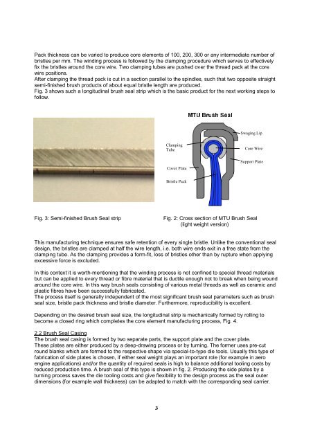
Pack thickness can be varied to produce core elements of 100, 200, 300 or any intermediate number of<br />
bristles per mm. The winding process is followed by the clamping procedure which serves to effectively<br />
fix the bristles around the core wire. Two clamping tubes are pushed over the thread pack at the core<br />
wire positions.<br />
After clamping the thread pack is cut in a section parallel to the spindles, such that two opposite straight<br />
semi-finished brush products of about equal bristle length are produced.<br />
Fig. 3 shows such a longitudinal brush seal strip which is the basic product for the next working steps to<br />
follow.<br />
˚<br />
Fig. 3: Semi-finished Brush Seal strip Fig. 2: Cross section of <strong>MTU</strong> Brush Seal<br />
(light weight version)<br />
This manufacturing technique ensures safe retention of every single bristle. Unlike the conventional seal<br />
design, the bristles are clamped at half the wire length, i.e. both wire ends exit in a free state from the<br />
clamping tube. As the clamping provides a form-fit, loss of bristles other than by rupture when applying<br />
excessive force is excluded.<br />
In this context it is worth-mentioning that the winding process is not confined to special thread materials<br />
but can be applied to every thread or fibre material that is ductile enough not to break when being wound<br />
around the core wire. In this way brush seals consisting of various metal threads as well as ceramic and<br />
plastic fibres have been successfully fabricated.<br />
The process itself is generally independent of the most significant brush seal parameters such as brush<br />
seal size, bristle pack thickness and bristle diameter. Furthermore, reproducibility is excellent.<br />
Depending on the desired brush seal size, the longitudinal strip is mechanically formed by rolling to<br />
become a closed ring which completes the core element manufacturing process, Fig. 4.<br />
2.2 Brush Seal Casing<br />
The brush seal casing is formed by two separate parts, the support plate and the cover plate.<br />
These plates are either produced by a deep-drawing process or by turning. The former uses pre-cut<br />
round blanks which are formed to the respective shape via special-to-type die tools. Usually this type of<br />
fabrication of side plates is chosen, if either seal weight plays an important role (for example in aero<br />
engine applications) and/or the quantity of required seals is high to balance additional tooling costs by<br />
reduced production time. A brush seal of this type is shown in fig. 2. Producing the side plates by a<br />
turning process saves the die tooling costs and give flexibility to the design process as the seal outer<br />
dimensions (for example wall thickness) can be adapted to match with the corresponding seal carrier.<br />
<br />
Clamping<br />
Tube<br />
Cover Plate<br />
Bristle Pack<br />
ÃÃ<br />
Swaging Lip<br />
Core Wire<br />
Support Plate


![Download PDF [5,37 MB] - MTU Aero Engines](https://img.yumpu.com/21945461/1/190x125/download-pdf-537-mb-mtu-aero-engines.jpg?quality=85)