Operating instructions - psg-online.de
Operating instructions - psg-online.de
Operating instructions - psg-online.de

You also want an ePaper? Increase the reach of your titles
YUMPU automatically turns print PDFs into web optimized ePapers that Google loves.
<strong>Operating</strong> <strong>instructions</strong><br />
Mikro-Series<br />
2016 Ring gate RX - A-version and H-version<br />
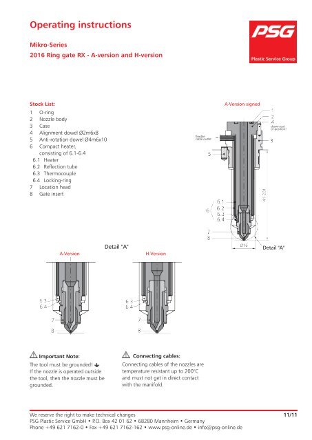
Stock List:<br />
1<br />
2<br />
3<br />
4<br />
5<br />
6<br />
6.1<br />
6.2<br />
6.3<br />
6.4<br />
7<br />
8<br />
O-ring<br />
Nozzle body<br />
Case<br />
Alignment dowel Ø2m6x8<br />
Anti-rotation dowel Ø4m6x10<br />
Compact heater,<br />
consisting of 6.1-6.4<br />
Heater<br />
Reflection tube<br />
Thermocouple<br />
Locking-ring<br />
Location head<br />
Gate insert<br />
Detail "A"<br />
A-Version H-Version<br />
Important Note:<br />
The tool must be groun<strong>de</strong>d!<br />
If the nozzle is operated outsi<strong>de</strong><br />
the tool, then the nozzle must be<br />
groun<strong>de</strong>d.<br />
flexible<br />
cable outlet<br />
Connecting cables:<br />
Connecting cables of the nozzles are<br />
temperature resistant up to 200°C<br />
and must not get in direct contact<br />
with the manifold.<br />
A-Version signed<br />
We reserve the right to make technical changes<br />
PSG Plastic Service GmbH • P.O. Box 42 01 62 • 68280 Mannheim • Germany<br />
Phone +49 621 7162-0 • Fax +49 621 7162-162 • www.<strong>psg</strong>-<strong>online</strong>.<strong>de</strong> • info@<strong>psg</strong>-<strong>online</strong>.<strong>de</strong><br />
drawn out<br />
of position!<br />
Detail "A"<br />
11/11
1. Installation of the Mikro nozzle<br />
1.1 Installation in the tool<br />
Install the nozzle into the nozzle fixing plate.<br />
Dowel pin (position 5) must be located.<br />
Note: Don’t damage Sealing surfaces!<br />
1.2 Assembly of the "Hot Half"<br />
Note: Insert the O-rings (1) into the groove of the nozzle flange before assembly.<br />
• The installation of the manifold can be ma<strong>de</strong>, after the height adjustment has already being ma<strong>de</strong> following<br />
<strong>instructions</strong> according to PSG.<br />
(See datasheet "Assembling instruction for standardized hot runner manifolds.")<br />
• Attention: Centring pin and dowel pin must be installed.<br />
Dowel pin (manifold)<br />
Anti-rotation dowel<br />
(nozzle)<br />
Plate guidance<br />
Sealing surfaces<br />
Manifold<br />
O-ring (1)<br />
Anti-rotation dowel<br />
(manifold)<br />
Mold plate<br />
Ante-chamber sealing<br />
Note: Plate guidance must work before immersing the nozzle into the ante-chamber sealing.<br />
2
2. Gate insert - dismantling (RX5/RX3)<br />
2.1 Gate insert-dismantling in the tool<br />
While changing the gate insert leave the mikro<br />
nozzle in the tool.<br />
Heater remains installed.<br />
To begin the cavity-plate must be pulled-down to<br />
reach the gate inserts.<br />
Important:<br />
1. Hot runner system must be cold (max. 40°C).<br />
2. Anti-rotation dowel must be fitted.<br />
2.1a Procedure<br />
- To remove the gate variants RX5 dismantle<br />
the gate insert cold.<br />
- In case of gate variant RX3 heat up the<br />
nozzle to 350°C and than dismantle.<br />
For all 2 variants the width across flats of<br />
the centring head is 9 mm..<br />
Achtung:<br />
Tightening torques see table 3.1.<br />
2.1.b Gate RX5 and RX3:<br />
Usually the gate insert sticks in the centering head.<br />
Then clamp carefully the centering head together<br />
with the gate insert at key area in a vice and remove<br />
the gate insert carefully out of the centering head<br />
with an ejection mandrel.<br />
The ejection mandrel can be self ma<strong>de</strong>, or purchased<br />
from PSG as a complete assembly / dismantling- <strong>de</strong>vice.<br />
(Art.no. 298410)<br />
Data about Angles are important for manufacturing,<br />
otherwise the gate insert could be damaged.<br />
The <strong>de</strong>pth of 4 mm is important so that the gate tip<br />
isn’t damaged.<br />
Ejection mandrel<br />
Key area<br />
3
2.2 Gate insert-dismantling outsi<strong>de</strong> of the tool<br />
IIf the nozzle isn´t installed, it´s advisable, to put it into the<br />
assembly / dismantling-<strong>de</strong>vice for changing the gate insert..<br />
If a assembly / dismantling-<strong>de</strong>vice isn´t available, clamp the<br />
nozzle at the joint of the nozzle body in a vice<br />
(use soft jaws!).<br />
Tightening torques see table 3.1.<br />
Than see procedure 2.1.a und 2.1.b<br />
3. Gate insert - assembly<br />
We recommend to assemble the gate insert only when the nozzle is already installed. The heater should be assembled.<br />
This means especially the gate insert type RX3, when it is nee<strong>de</strong>d to heat the nozzle up 350°C (see point 3.1).<br />
Note that the sealing surfaces are free from plastic.<br />
Example: RX-gate:<br />
Step 1: Assemble the gate insert (8) in the centering head (7).<br />
Step 2: Now both are screwed together into the nozzle body (2).<br />
Sealing surfaces<br />
Finally, tighten up to the recommen<strong>de</strong>d torque, see table 3.1.<br />
Note the temperature!<br />
Assembly-/<br />
dismantling-<strong>de</strong>vice Unscrew<br />
centring head<br />
Unscrew<br />
centring head<br />
4
3.1 Tightening torques for the 2016 gate insert types<br />
Gate insert Torque Spanner opening<br />
RX5 8 Nm (nozzle cold) SW 9<br />
RX3<br />
4. Heater dismantling<br />
8 Nm cold tighten and then to<br />
350°C heat and with 8 Nm<br />
pull tight again!<br />
Important!<br />
SW 9<br />
- The nozzle must be taken out of the tool.<br />
Remove the case by inserting the nozzle at the flange joint of the nozzle<br />
body into a vice with soft jaws.<br />
Don’t tighten the vice, otherwise the nozzle body will not be pressed down<br />
wards out of the case.<br />
- Be careful that the heater outlet / sleeve does not lay on the jaws of the vice,<br />
otherwise it will be damaged or pulled off by pressing down.<br />
- The nozzle body can be pressed out of the case with the help of the<br />
assembly/dismantling sleeve.<br />
This can be self ma<strong>de</strong>, or purchased from PSG as a complete assembly/<br />
dismantling-<strong>de</strong>vice.<br />
Assembly/<br />
Dismantling<br />
sleeve<br />
5
- Remove the semi-locking ring.<br />
Afterwards the compact heater with the ring thermocouple can be removed.<br />
How to use ring thermal extractor (see pictures).<br />
Detail X<br />
Semi-locking<br />
ring<br />
Note:<br />
Push the heater push down at the same time and<br />
be very carefully, since the ring thermocouple can<br />
easily break of.<br />
Alternatively, press up (don´t lever) the ring at the thermocouple with a screwdriver from the nozzle body<br />
gently step by step.<br />
Screwdriver<br />
Detail X<br />
6
5. Heater assembly<br />
Supplied: View:<br />
Heater +<br />
Semi-locking ring<br />
(circlip)<br />
Adjacent:<br />
Bend the lead exit radial by<br />
hand.<br />
- The heater easily onto the nozzle body.<br />
Push the ring thermocouple (6.3) carefully onto the nozzle body (2).<br />
Push down the heater (6.1) at the same time. There must always be a gap between heater (6.1) and<br />
ring thermocouple (6.3) of approx. 1.5 mm.<br />
A assembly/dismantling sleeve (see next page) can be used to press on the ring thermocouple (6.3).<br />
Firm seat must be ensured.<br />
Rotate heater to ensure that the cable outlet aligns with the cut-out in the case.<br />
Firm seat<br />
Note, that the outlet fits<br />
in the cut out from the<br />
case.<br />
7
The shown assembly/dismantling sleeve case can be manufactured by the customer, or can be bought from<br />
PSG as a complete unit.<br />
Put the assembly/dismantling sleeve on the<br />
ring thermocouple (6.3) and press the<br />
ring thermocouple (6.3) carefully on the front<br />
of the nozzle body (by hand) while pushing<br />
down the heater (6.1) at the same time.<br />
- Semi-locking ring is to assemble.<br />
We recommend to use the new.<br />
(Spare part-heater inclusive)<br />
Assembly/<br />
Dismantling sleeve<br />
Semi-locking ring<br />
(circlip)<br />
- Clamp the case (3) carefully into a vice (soft jaws). The cylindrical pin (4) must be present. Now lay the<br />
nozzle with the assembled compact heater (6) on the case (3). The cylindrical pin must align in the cut<br />
out on the nozzle body (2) and the cut out on the case (3) must match to the cable outlet of the<br />
compact heater. With light strikes (best with a plastic hammer) push the body (2) onto the case (3), until<br />
no gap is remaining.<br />
Cut out<br />
Sealing surface<br />
to be damaged.<br />
No gap<br />
8
6. O-Ring<br />
• Test phase, short-time serial production:<br />
It is not necessary to exchange the o-ring if no plastic has penetrated into the O-ring groove.<br />
Otherwise the o-ring has to be exchanged!<br />
• For longer serial production:<br />
If maintenance for the tool is necessary, it is recommen<strong>de</strong>d that the o-rings are replaced, even if no<br />
plastic has penetrated into the o-ring groove.<br />
7. Assembly- / Dismantling <strong>de</strong>vice<br />
• For the assembly -, dismantling <strong>de</strong>vice it is planned to have<br />
diameter 21mm for the 2016 mikro nozzle and with<br />
diameter 24mm for the 2016 mikro frontal nozzle.<br />
• The ejection mandrel (a) and the assembly/dismantling<br />
sleeve (b) are components of the <strong>de</strong>vice.<br />
• The M8x0,75 thread is used for the ejection mandrel gate<br />
insert. At the same time the assembly/dismantling sleeve is<br />
used as a receiving tank for the gate insert.<br />
• The centering head lays flat on the <strong>de</strong>vice and<br />
the gate insert can be removed with ejection mandrel<br />
from the centering head.<br />
• Or<strong>de</strong>r number for assembly-, dismantling <strong>de</strong>vice is 298 410.<br />
* You can see a screwed centring head (7) with gate insert (8).<br />
for 2016<br />
Standard<br />
for 2016<br />
Front<br />
9