ESD Protection Device Simulation and Design - Silvaco
ESD Protection Device Simulation and Design - Silvaco
ESD Protection Device Simulation and Design - Silvaco

You also want an ePaper? Increase the reach of your titles
YUMPU automatically turns print PDFs into web optimized ePapers that Google loves.
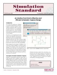
<strong>ESD</strong> <strong>Protection</strong> <strong>Device</strong> <strong>Simulation</strong> <strong>and</strong><br />
<strong>Design</strong>
Introduction<br />
Electrostatic Discharge (<strong>ESD</strong>) is one of the major reliability issues<br />
in Integrated Circuits today<br />
<strong>ESD</strong> is a high current (1A) short duration (1ns to 100ns) event<br />
<strong>Simulation</strong> gives physical insight into what mechanisms cause<br />
<strong>ESD</strong> destruction <strong>and</strong> how device designs can be altered to be<br />
more resistant to <strong>ESD</strong><br />
When modeling electrothermal interactions in semiconductor<br />
devices experiencing <strong>ESD</strong> pulses time–dependency <strong>and</strong> lattice<br />
heating must be included<br />
Real test conditions require that the device <strong>and</strong> its interaction with<br />
an external circuit are both simulated<br />
<strong>Simulation</strong> of Electrothermal Interactions in <strong>ESD</strong> <strong>Protection</strong> <strong>Device</strong>s<br />
- 2 -
Electrostatic Discharge (<strong>ESD</strong>) <strong>Simulation</strong><br />
Q1: Which <strong>Simulation</strong> Tools Are Used For <strong>ESD</strong> Related<br />
Problems?<br />
Q2: How are <strong>Silvaco</strong> Tools used for <strong>ESD</strong> <strong>Simulation</strong>?<br />
<strong>Simulation</strong> of Electrothermal Interactions in <strong>ESD</strong> <strong>Protection</strong> <strong>Device</strong>s<br />
- 3 -
Giga- Electrothermal Effects in Semiconductors<br />
ATLAS/Giga solves self-consistently the drift-diffusion<br />
semiconductor equations <strong>and</strong> the heat flow equation in the<br />
semiconductor <strong>and</strong> the heat sinks<br />
Self-consistent solution of the heat flow equation using Wachutka’s<br />
thermodynamically rigorous model which includes all thermal sources<br />
(Joule, Thomson <strong>and</strong> Recombination Heat)<br />
Dependencies of all electrical <strong>and</strong> thermal material parameters on the<br />
local lattice temperature (mobility, impact ionization, etc.)<br />
Arbitrary thermal boundary conditions, including thermal resistors <strong>and</strong><br />
heat sinks, are allowed<br />
DC <strong>and</strong> transient analysis<br />
<strong>Simulation</strong> of Electrothermal Interactions in <strong>ESD</strong> <strong>Protection</strong> <strong>Device</strong>s<br />
- 4 -
MixedMode- <strong>Device</strong>-Circuit Interactions<br />
ATLAS/Giga/MixedMode solves both the embedded physically<br />
based ATLAS devices <strong>and</strong> the connected spice circuit elements,<br />
simultaneously <strong>and</strong> self-consistently to provide a complete circuit<br />
solution to <strong>ESD</strong> event.<br />
Links ATLAS devices to a SPICE type circuit simulator<br />
Multiple ATLAS devices with independent models may be included in a<br />
single circuit<br />
The SPICE input language is used for circuit specification<br />
The usual SPICE primitives are available, <strong>and</strong> most commercially<br />
developed SPICE models are supported<br />
DC <strong>and</strong> transient analysis<br />
<strong>Simulation</strong> of Electrothermal Interactions in <strong>ESD</strong> <strong>Protection</strong> <strong>Device</strong>s<br />
- 5 -
Curvetracer- Load Line Approach<br />
Dynamic Load Line Approach from “An Automatic Biasing<br />
Scheme for Tracing Arbitrarily Shaped IV Curves”, Goosens et al.,<br />
IEEE Trans CAD 1994, Vol 13, pp. 310-317<br />
Automatic boundary condition selection<br />
Automatic selection of voltage/current step size<br />
A single SOLVE statement can be used to trace entire curves<br />
Only in DC mode. Transient <strong>and</strong> MixedMode already have similar<br />
capability<br />
<strong>Simulation</strong> of Electrothermal Interactions in <strong>ESD</strong> <strong>Protection</strong> <strong>Device</strong>s<br />
- 6 -
Extended Precision Mode<br />
ATLAS supports different arithmetic precision. Supported<br />
precision levels include:<br />
Precision (bits): 64 80 128 160 256<br />
For well-converged solutions, run-time increases with precision.<br />
The increase is especially significant at the highest precision<br />
levels. On the other h<strong>and</strong>, certain problems that have difficulty<br />
converging at the lower precision levels are likely to run faster if<br />
the precision level is increased<br />
<strong>Simulation</strong> of Electrothermal Interactions in <strong>ESD</strong> <strong>Protection</strong> <strong>Device</strong>s<br />
- 7 -
Extended Precision Mode<br />
Here is an example illustrating the effect of numerical precision on the simulation results for a<br />
silicon MOSFET. The figure above compares the contours of the hole current density, computed in<br />
64-bit <strong>and</strong> in 80-bit precision. These noise levels are strictly attributable to the round-off errors from<br />
finite-precision arithmetic. For this device, it appears that round-off error is the dominant<br />
contribution to the noise level for precisions up to 128-bits.<br />
<strong>Simulation</strong> of Electrothermal Interactions in <strong>ESD</strong> <strong>Protection</strong> <strong>Device</strong>s<br />
- 8 -
Comprehensive TMA Compatibility<br />
SILVACO <strong>and</strong> TMA TCAD software share a common legacy from<br />
Stanford University<br />
ATHENA is T-Supreme4 compatible<br />
ATLAS is MEDICI compatible<br />
This compatibility allows:<br />
Direct loading of input deck syntax<br />
Support for the same physical models<br />
Use of the same legacy material parameters<br />
Direct loading of TMA TIF format structure files<br />
Sharing of users’ existing calibration coefficients<br />
TMA Users can migrate to SILVACO software easily<br />
T-Supreme4 <strong>and</strong> MEDICI are trademarks of Synopsis Inc<br />
<strong>Simulation</strong> of Electrothermal Interactions in <strong>ESD</strong> <strong>Protection</strong> <strong>Device</strong>s<br />
- 9 -
Typical Application Examples<br />
ATLAS <strong>Simulation</strong> Results<br />
Silicon Controlled Rectifier (SCR) Latch-up<br />
ATLAS/Giga <strong>Simulation</strong> Results<br />
CMOS <strong>Protection</strong> <strong>Device</strong> Under HBM Test<br />
MOS Second Breakdown<br />
ATLAS/Giga/MixedMode <strong>Simulation</strong> Results<br />
CMOS <strong>Protection</strong> <strong>Device</strong> Under CDM Test<br />
SmartSpice <strong>Simulation</strong> Results<br />
CMOS <strong>Protection</strong> <strong>Device</strong> Under HBM Test<br />
<strong>Simulation</strong> of Electrothermal Interactions in <strong>ESD</strong> <strong>Protection</strong> <strong>Device</strong>s<br />
- 10 -
SCR Latch-up<br />
SCR Process <strong>Simulation</strong><br />
<strong>Simulation</strong> of Electrothermal Interactions in <strong>ESD</strong> <strong>Protection</strong> <strong>Device</strong>s<br />
- 11 -
SCR Latch-up<br />
DC Latch-up <strong>Simulation</strong> Step<br />
1. Bias Vdd <strong>and</strong> Nwell to 5V<br />
2. Apply positive bias ramp to Vdd, trace curve until Idd=1mA/um<br />
3. Apply negative bias ramp to Vss, trace curve until Iss=1mA/um<br />
4. Analyze curve to measure trigger voltage <strong>and</strong> holding current<br />
<strong>Simulation</strong> of Electrothermal Interactions in <strong>ESD</strong> <strong>Protection</strong> <strong>Device</strong>s<br />
- 12 -
SCR Latch-up<br />
Positive DC bias on Vdd<br />
<strong>Simulation</strong> of Electrothermal Interactions in <strong>ESD</strong> <strong>Protection</strong> <strong>Device</strong>s<br />
- 13 -
SCR Latch-up<br />
Transient <strong>Device</strong> <strong>Simulation</strong> Setup<br />
1. Bias Vdd <strong>and</strong> Nwell to 5V<br />
2. Apply -1V pulse to Vss for several nanoseconds<br />
3. Return Vss to zero continue simulation for 1us<br />
4. Analyze current-time plot to analyze trigger point<br />
<strong>Simulation</strong> of Electrothermal Interactions in <strong>ESD</strong> <strong>Protection</strong> <strong>Device</strong>s<br />
- 14 -
SCR Latch-up<br />
Current vs. Time During Transient Latchup<br />
<strong>Simulation</strong> of Electrothermal Interactions in <strong>ESD</strong> <strong>Protection</strong> <strong>Device</strong>s<br />
- 15 -
SCR Latch-up<br />
Potential contours <strong>and</strong> Current flowline<br />
Before triggering During triggering After triggering<br />
<strong>Simulation</strong> of Electrothermal Interactions in <strong>ESD</strong> <strong>Protection</strong> <strong>Device</strong>s<br />
- 16 -
CMOS <strong>Protection</strong> <strong>Device</strong> Under HBM Test<br />
HBM model consists of a 10ns linear current ramp followed by an<br />
exponential current drop with a time constant of 150ns<br />
For realistic simulation it is necessary to model the self-heating at<br />
high current levels. The local heating has to be combined with<br />
temperature dependent models for mobility, recombination <strong>and</strong><br />
impact ionization. The combination of the complex transient pulse<br />
<strong>and</strong> advanced models means that <strong>ESD</strong> pulse simulations are<br />
computationally intensive.<br />
<strong>Simulation</strong> of Electrothermal Interactions in <strong>ESD</strong> <strong>Protection</strong> <strong>Device</strong>s<br />
- 17 -
CMOS <strong>Protection</strong> <strong>Device</strong> Under HBM Test<br />
MOS structure was<br />
created using ATHENA<br />
A high current pulse was<br />
applied to the device<br />
according to the HBM<br />
st<strong>and</strong>ard<br />
ATLAS records the peak<br />
temperature in the<br />
device at each time step<br />
of the simulation<br />
Due to heat capacity the<br />
maximum temperature<br />
occurs significantly later<br />
than the peak current<br />
<strong>Simulation</strong> of Electrothermal Interactions in <strong>ESD</strong> <strong>Protection</strong> <strong>Device</strong>s<br />
Peak temperature in MOSFET during an HBM<br />
<strong>ESD</strong> current pulse."<br />
- 18 -
CMOS <strong>Protection</strong> <strong>Device</strong> Under HBM Test<br />
Location of the hot<br />
spot within the<br />
device<br />
<strong>Simulation</strong> of Electrothermal Interactions in <strong>ESD</strong> <strong>Protection</strong> <strong>Device</strong>s<br />
- 19 -
CMOS <strong>Protection</strong> <strong>Device</strong> Under HBM Test<br />
Typical applications of <strong>ESD</strong> simulations are to examine the <strong>ESD</strong><br />
performance of different drain engineering designs, to examine<br />
the position of the drain contact with respect to the hot spot <strong>and</strong> to<br />
observe the peak electric field across the gate oxide<br />
This simulation was executed using parallel ATLAS with<br />
increasing number of processors. The reduction in execution time<br />
vs the number of processors is shown in the following slides. A<br />
high efficiency is seen even though the mesh used is not large<br />
<strong>Simulation</strong> of Electrothermal Interactions in <strong>ESD</strong> <strong>Protection</strong> <strong>Device</strong>s<br />
- 20 -
CMOS <strong>Protection</strong> <strong>Device</strong> Under HBM Test<br />
<strong>Simulation</strong> of Electrothermal Interactions in <strong>ESD</strong> <strong>Protection</strong> <strong>Device</strong>s<br />
Execution time improvement with<br />
number of processors for <strong>ESD</strong> pulse simulation.<br />
- 21 -
MOS Second Breakdown<br />
The thermally dominated<br />
second breakdown voltage in<br />
MOSFETs can be predicted<br />
using Giga<br />
An isothermal simulation<br />
under the same conditions<br />
fails to show the second<br />
breakdown<br />
The simulated DC results<br />
provided by Giga, such as<br />
second breakdown voltages<br />
<strong>and</strong> trigger current, are useful<br />
for determining <strong>ESD</strong> pulse<br />
tolerance<br />
<strong>Simulation</strong> of Electrothermal Interactions in <strong>ESD</strong> <strong>Protection</strong> <strong>Device</strong>s<br />
- 22 -
CMOS <strong>Protection</strong> <strong>Device</strong> Under CDM Test<br />
MixedMode2D/3D circuits can include up to 200 nodes, 300 elements,<br />
<strong>and</strong> up to 10 physically-based ATLAS devices<br />
The circuits are specified using the SPICE input language.<br />
MixedMode2D/3D utilizes the SmartSpice Analog Circuit Simulator model<br />
library to provide an accurate <strong>and</strong> comprehensive description of the<br />
circuit elements<br />
<strong>Simulation</strong> of Electrothermal Interactions in <strong>ESD</strong> <strong>Protection</strong> <strong>Device</strong>s<br />
- 24 -
CMOS <strong>Protection</strong> <strong>Device</strong> Under HBM Test<br />
SmartSpice simulation results showing<br />
the capacitance discharge <strong>and</strong> the<br />
resulting current in the DUT<br />
<strong>Simulation</strong> of Electrothermal Interactions in <strong>ESD</strong> <strong>Protection</strong> <strong>Device</strong>s<br />
- 25 -<br />
Circuit Schematic for HBM model definition
Conclusion<br />
<strong>ESD</strong> is a real threat to IC reliability<br />
Treating <strong>ESD</strong>-related problem is very challenging<br />
The use of TCAD helps to underst<strong>and</strong> <strong>and</strong> optimize <strong>ESD</strong> design<br />
protection <strong>and</strong> therefore reducing IC development costs <strong>and</strong> time<br />
However specific device physics <strong>and</strong> numerics are needed to<br />
obtain reliable results<br />
Automation <strong>and</strong> Optimization can be performed using Virtual<br />
Wafer Fab<br />
<strong>Simulation</strong> of Electrothermal Interactions in <strong>ESD</strong> <strong>Protection</strong> <strong>Device</strong>s<br />
- 26 -