EE Web PULSE
EE Web PULSE
EE Web PULSE

Create successful ePaper yourself
Turn your PDF publications into a flip-book with our unique Google optimized e-Paper software.
<strong>EE</strong><strong>Web</strong><br />
<strong>PULSE</strong><br />
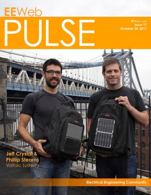
Jeff Crystal &<br />
Phillip Stearns<br />
Voltaic Systems<br />
<strong>EE</strong><strong>Web</strong>.com<br />
Issue 17<br />
October 25, 2011<br />
Electrical Engineering Community
It’s all about<br />
connections. <strong>EE</strong><strong>Web</strong><br />
Electrical Engineering Community<br />
engineers<br />
hobbyists<br />
discussions<br />
power<br />
microcontroller<br />
Digi-Key is an authorized distributor for all supplier partners. New products added daily.<br />
© 2011 Digi-Key Corporation, 701 Brooks Ave. South, Thief River Falls, MN 56701, USA<br />
Contact Us For Advertising Opportunities<br />
The user-to-user forum is for everyone, from<br />
design engineers to hobbyists, to discuss<br />
technology, products, designs and more.<br />
Join the discussions that match your interest<br />
or offer your expertise to others.<br />
Join the discussion now at:<br />
students<br />
industry experts<br />
1.800.574.2791<br />
advertising@eeweb.com<br />
www.eeweb.com/advertising<br />
community<br />
wireless<br />
www.digikey.com/techxchange<br />
technical documents<br />
lighting<br />
sensor<br />
resources<br />
application notes<br />
white papers<br />
links<br />
reference designs
TABLE OF CONTENTS<br />
Jeff Crystal and Phillip Stearns 4<br />
VOLTAIC SYSTEMS<br />
Interview with Jeff Crystal, COO and Phillip Stearns, Lead Product Development<br />
and Testing Technician<br />
Featured Products 8<br />
Hardcore Micros - Microchip’s PIC10F32x 10<br />
BY PAUL CLARKE WITH EBM-PAPST<br />
A look at the new and interesting features coming to PIC Microcontrollers.<br />
MPLS-TP: Emerging Technology for 14<br />
Packet Transport Network<br />
BY RISHI CHUGH WITH ALTERA<br />
An introduction to Multi-Protocol Label Switching-Transport Profile as a new, emerging<br />
technology.<br />
RTZ - Return to Zero Comic 18<br />
<strong>EE</strong><strong>Web</strong> | Electrical Engineering Community Visit www.eeweb.com 3<br />
TABLE OF CONTENTS
INTERVIEW<br />
Jeff Crystal &<br />
Phillip Stearns<br />
How did you get into<br />
electronics/engineering and<br />
when did you start?<br />
Jeff: I majored in biomedical<br />
engineering at Tulane, which had<br />
a big circuits component, but I<br />
really wasn’t able to put my degree<br />
to use as I went into management<br />
consulting and then software<br />
startups. One of the joys of starting<br />
with Voltaic was the opportunity to<br />
get hands-on again with electronics<br />
and physical devices.<br />
Phil: I was always curious about<br />
electronics and started tinkering<br />
with one of those Radioshack 30 in<br />
1 electronics labs in grade school.<br />
Most of that curiosity, however,<br />
was sated by opening electronic<br />
devices and prodding about their<br />
insides. Putting them back together<br />
in working order, though, was a<br />
whole other story. I gained all of my<br />
knowledge of basic theory when<br />
studying engineering physics at the<br />
University of Colorado at Boulder,<br />
before transferring to the Denver<br />
Jeff Crystal - COO (right)<br />
Phillip Stearns - Lead Product Development and Testing Technician (left)<br />
Voltaic Systems<br />
campus to study audio engineering,<br />
where I explored the practical<br />
applications of that theory in music<br />
production.<br />
What’s fun about solar?<br />
Jeff: It’s like flying. You know<br />
technically how an airplane<br />
functions but every time I take off<br />
from a runway, I’m like, “Wow,<br />
this really works.” It is the same<br />
thing with solar. I use it every day,<br />
but when I take a solar panel and<br />
connect it to a battery or a device<br />
or a light and it powers it up, I get<br />
a little thrill. Luckily, learning to use<br />
solar is a little easier than learning<br />
how to fly.<br />
Phil: It is incredibly liberating to<br />
realize that it’s possible to generate<br />
power without having to plug into a<br />
wall. I have the most fun dreaming<br />
up creative ways of integrating<br />
small-scale solar in sculptures and<br />
other artworks. Teaching solar is a<br />
very rewarding experience too.<br />
What are your favorite<br />
hardware tools that you use?<br />
Jeff: For what we’re doing, a<br />
multimeter or two is really the<br />
everyday tool we depend on.<br />
<strong>EE</strong><strong>Web</strong> | Electrical Engineering Community Visit www.eeweb.com 4<br />
FEATURED INTERVIEW
INTERVIEW<br />
Phil: I really like the Array 3710<br />
programmable load and the Array<br />
3644 programmable bench supply.<br />
The two in combination allow for<br />
detailed analysis of battery charging<br />
and discharging characteristics.<br />
What are your favorite<br />
software tools that you use?<br />
Jeff: This may sound funny, but we<br />
use PowerPoint all the time to draw<br />
up specs on all sorts of things. For<br />
the most part, we’re not doing circuit<br />
level design, we’re specifying the<br />
physical design and the behavior.<br />
It allows us to work really quickly<br />
to build specifications on a wide<br />
range of components.<br />
Phil: I’m a hardware guy.<br />
What is the hardest/trickiest<br />
bug you have ever fixed?<br />
Jeff: For me, it is the actual<br />
manufacturing of components.<br />
We’re dealing with over 15<br />
suppliers and we’re trying to work<br />
with them to make the highest<br />
quality components. Even with<br />
simple components like phone<br />
adapters that you’d think should<br />
have zero problems, it turns out that<br />
sometimes the supplier solders a<br />
bit wrong, so it breaks if you bend<br />
it too far. We’re constantly getting<br />
samples, trying to break them,<br />
and making suggestions on how<br />
to manufacture them for better<br />
durability. I’d love to say that we<br />
have “fixed” this, but the reality<br />
is that we will always be making<br />
improvements to our components.<br />
Phil: Charging Apple products is a<br />
tricky affair, and it took a bit of reverse<br />
engineering and conversations with<br />
our suppliers to figure out. All the<br />
Apple products charge using OEM<br />
cables and docks, most of which<br />
plug into an AC power adapter via<br />
USB. What we learned was that all<br />
four pins of the USB connector are<br />
used to communicate to the Apple<br />
device telling it how much power it<br />
can draw, and these vary by Apple<br />
device. For the time being, we<br />
seem to have it all figured out, but<br />
with Apple constantly upgrading<br />
its products and changing its<br />
standard, who knows how long it<br />
will be before we have to figure it<br />
out all over again.<br />
It is incredibly<br />
liberating to realize<br />
that it’s possible<br />
to generate power<br />
without having to<br />
plug into a wall.<br />
What is on your bookshelf?<br />
Jeff: A lot of books on economic<br />
development, plus too many Nordic<br />
mystery novels. I use the <strong>Web</strong> for<br />
most of my engineering information.<br />
Phil: A healthy mix of electronic<br />
references, critical theory, sound<br />
and art theory, modern physics, and<br />
gardening books: A well worn copy<br />
of The Art of Electronics by Horowitz<br />
and Hill, several different selections<br />
from Don Lancaster’s Cookbook<br />
series, Baudrillard, Virillio, Zizek,<br />
Agamben, John Cage’s Silence,<br />
Harry Partch’s Genesis of a Music,<br />
How to Imagine by Gianfranco<br />
Baruchello, and The One-Straw<br />
Revolution by Masanobu Fukuoka<br />
are just a few of my favorites.<br />
What online resources<br />
do you use?<br />
Jeff: I spend a decent amount of<br />
time on Adafruit.com—sometimes<br />
for their technical explanations,<br />
which are simple, but written very<br />
well. I also look to them as a model<br />
for sharing information I’ve learned<br />
about almost anything, and sharing<br />
it with the world. We’re not as good<br />
as them at this and might not ever<br />
be, but we really love how open they<br />
are about sharing and teaching.<br />
Phil: Google. Whenever there’s a<br />
part (especially ICs) that I encounter<br />
in the field that I’m not familiar with,<br />
I pop the part number into Google<br />
and can usually pull up a datasheet<br />
a few clicks later. Wikipedia is also<br />
good for refreshing my memory and<br />
filling in any gaps in knowledge. If<br />
the answers aren’t in either of those<br />
places, I tend to turn to the books.<br />
Do you have any tricks<br />
up your sleeve?<br />
Phil: Unrelated to my work at Voltaic,<br />
I circuit bend devices (intentionally<br />
short circuit components) to<br />
induce erratic output. It’s an<br />
anti-engineering approach to<br />
producing art with electronics.<br />
You can see some images I’ve<br />
produced with low resolution digital<br />
cameras http://continentcontinent.<br />
cc/index.php/continent/article/<br />
viewArticle/27. Because we as a<br />
society haven’t fully dealt with the<br />
end-of-life issues of our electronic<br />
devices, fully functional machines<br />
can be found on the street awaiting<br />
trash collection. These discarded<br />
electronic devices are becoming<br />
fodder for a growing art movement<br />
<strong>EE</strong><strong>Web</strong> | Electrical Engineering Community Visit www.eeweb.com 5<br />
FEATURED INTERVIEW
INTERVIEW<br />
that involves using them as raw<br />
material for creative projects.<br />
What has been your<br />
favorite project?<br />
Jeff: Recently, getting our iPad solar<br />
charger (http://www.voltaicsystems.<br />
com/) out was a lot of fun. There<br />
are a lot of people doing things<br />
around phone charging, but no one<br />
had really done anything close to<br />
the right design, performance, and<br />
price for tablets. On the engineering<br />
side, there were a lot of tradeoffs<br />
about cost, weight, charge times,<br />
and device compatibility we had to<br />
think through. I think we’re happiest<br />
when we can be building products<br />
that no one else is.<br />
Do you have any note-worthy<br />
engineering experiences?<br />
Jeff: The first time that we<br />
connected one of our batteries in<br />
development to a device and the<br />
battery started smoking. I think<br />
we all learned the importance of<br />
over-discharge protection at that<br />
moment. We also got more formal<br />
on the battery testing process to<br />
make sure the things we specified<br />
actually made it into the product.<br />
Phil: When I took on learning how<br />
to build my own bench supply, I<br />
connected my first linear supply<br />
circuit to the mains, and almost<br />
immediately both of the large filter<br />
capacitors popped and started<br />
venting a noxious smelling smoke. It<br />
took three days and several cans of<br />
air freshener for the smell to go away.<br />
It was an important lesson in double<br />
checking electrical connections<br />
and matching component specs<br />
to project demands; a postmortem<br />
examination revealed that I had<br />
wired the transformer backwards!<br />
What are you currently<br />
working on?<br />
Jeff: We’re working on solar LED<br />
lighting. LEDs are getting more<br />
powerful and cheaper. And to<br />
some extent, so are batteries and<br />
solar panels. This means that it<br />
will become economical for a safe,<br />
clean lighting source to replace<br />
unsafe, dirty, and expensive lighting<br />
sources like kerosene across the<br />
globe.<br />
Phil: A big project that we’re<br />
coming close to finishing is our<br />
line of laptop chargers. We’ve been<br />
tweaking designs for optimum<br />
efficiency charging from solar, as<br />
well as making sure the batteries<br />
can supply power for the most<br />
demanding laptops on the market<br />
today. We hope to release our new<br />
high-power systems in the fall. On<br />
the low power side of things we’re<br />
taking on NiMH battery charging,<br />
and are developing a AA battery<br />
charger optimized for charging<br />
from solar.<br />
What direction do you see<br />
your business heading<br />
in the next few years?<br />
Jeff: We think there is a conversion<br />
happening from AC to DC. If you<br />
think about LED lighting as well as<br />
our phones and tablets (becoming<br />
the defacto TV), you can power a lot<br />
of things in a home without AC. From<br />
a solar perspective, this means you<br />
don’t need an inverter. You don’t<br />
need a big lead acid battery. You<br />
need a small to moderate sized<br />
solar panel and a compact lithiumion<br />
or lithium-polymer battery. We<br />
think this will make the economics<br />
of solar much more effective and<br />
practical for low and middle-income<br />
families around the globe.<br />
What challenges do you<br />
foresee in our industry?<br />
Jeff: In consumer electronics, size<br />
and performance are always an<br />
issue. People want things smaller<br />
and cheaper. The issue is that solar<br />
cells really haven’t gotten that much<br />
more efficient. So when people<br />
buy products with a tiny little solar<br />
panel on it, they may think it is<br />
cute but the end result is that it just<br />
doesn’t work that well and they end<br />
up souring on all of solar. I think<br />
properly setting expectations and<br />
educating masses of people who<br />
have been trained on plugging<br />
things into perfectly functioning<br />
wall outlets on how to use solar will<br />
take some time.<br />
I think the other challenge will be<br />
dealing with end-of-life issues. In a<br />
decade or so, there will be a lot of<br />
solar panels and batteries that have<br />
stopped functioning properly. Are<br />
these recycled properly? Can we<br />
recover the value from them. I don’t<br />
think that has been worked out.<br />
Phil: The challenge of educating<br />
people is a major issue. I see the<br />
portable solar market as a path<br />
toward marketing larger utilitybased<br />
approaches to solar energy<br />
production. If many people are<br />
having poor experiences with<br />
portable solar charging, then<br />
that will inform their attitudes<br />
toward proposals for larger scale<br />
installations in their communities.<br />
Sadly, not all of us are convinced<br />
that solar is worth the expense,<br />
otherwise we’d see panels covering<br />
rooftops and southern-facing office<br />
buildings everywhere. Ultimately,<br />
the larger scale utility-focused<br />
installations are where solar’s<br />
greatest potential lies. Making<br />
<strong>EE</strong><strong>Web</strong> | Electrical Engineering Community Visit www.eeweb.com 6<br />
FEATURED INTERVIEW
INTERVIEW<br />
solar portable means that people<br />
will carry it with them, which is<br />
great, except that we spend much<br />
of our time indoors. This means the<br />
resources used in making portable<br />
charging systems are not being<br />
utilized to their maximum potential.<br />
Permanent outdoor installations will<br />
gather and convert solar energy<br />
whenever it’s available rather<br />
than only when availability and<br />
circumstance intersect to place<br />
the user of portable solar outdoors<br />
during a sunny day. In addition<br />
to being able to charge on the go<br />
(while biking to work), plugging<br />
devices into outlets powered by<br />
panels on the roof makes sense.<br />
A challenge I see is integrating<br />
portable solar products with grid<br />
interactive systems so that every<br />
little watt has the chance to add up.<br />
Additionally, the manufacturing<br />
processes used to make portable<br />
solar resilient and durable also<br />
contribute to the end-of-life issues.<br />
Monocrystalline and polycrystalline<br />
silicon are easily recycled, but<br />
not if they’re encased in epoxy.<br />
Newer, more efficient thin film solar<br />
appears to satisfy the durability<br />
requirement when mounted on<br />
a suitable substrate, but will also<br />
have to address issues of recycling,<br />
especially due to the increased<br />
use of exotic materials. As Jeff said,<br />
there is a lot left to be worked out<br />
when it comes to dealing with endof-life<br />
issues.<br />
What are you doing on the<br />
environmental side of things?<br />
Jeff: In addition to the big idea<br />
that we’re helping people generate<br />
their own power and helping them<br />
create street-level conversations<br />
about alternative energy, the<br />
biggest change in the production<br />
of components of the last few years<br />
has been RoHS standards. We<br />
select suppliers who comply with<br />
RoHS and require it any place it<br />
applies. We’re also trying to get<br />
more of our own components back<br />
in-house from customers so that we<br />
can reuse or recycle them properly.<br />
I think we can get a lot better here<br />
though. ■<br />
Automotive, Medical, Telecom, POS<br />
LCD for Any Application<br />
Microtips Technology<br />
QVGA Green<br />
w/LED Backlight<br />
240 x 160 COG<br />
w/LED Backlight<br />
7” High Bright<br />
From design to service, Microtips offers a variety of<br />
competitively priced Liquid Crystal Display modules<br />
which includes standard character and graphic<br />
monochrome, passive and active color displays with<br />
white LED as well as custom LCD modules and<br />
complete OEM services.<br />
For your own design needs please contact<br />
Microtips Technology:<br />
www.microtipsusa.com<br />
1.888.499.8477<br />
mtusainfo@microtipsusa.com<br />
<strong>EE</strong><strong>Web</strong> | Electrical Engineering Community Visit www.eeweb.com 7<br />
FEATURED INTERVIEW
FEATURED PRODUCTS<br />
Oscilloscopes with Waveform Generator<br />
Agilent Technologies Inc. added optional arbitrary waveform generation<br />
capability and five new analysis applications to its InfiniiVision 3000<br />
X-Series oscilloscopes. AWG makes it easy for engineers to capture<br />
waveforms with their oscilloscopes and instantly convert them to stimulus<br />
files to simplify stimulus/response testing. Nine months ago, Agilent was<br />
the first major test-instrument vendor to integrate a function generator<br />
with an oscilloscope. This integration is popular with manufacturers<br />
who want to simplify stimulus-response testing, R&D engineers who<br />
need to simulate missing signals and educators who want a simple<br />
tool for teaching students about instrument operation. Now the company has become the first to add AWG to its<br />
oscilloscopes. Agilent is including this software upgrade – which is used with the integrated WaveGen 20-MHZ<br />
function generator option – at no additional cost. For more information, please click here.<br />
Embedded Motor Control Dev Kit<br />
Microchip Technology Inc., a leading provider of microcontroller,<br />
analog and Flash-IP solutions, and Digilent®, Inc., today announced<br />
the availability of a Microchip dsPIC33 Digital Signal Controller (DSC)based<br />
development kit. The Digilent® Cerebot MC7 Development<br />
Kit addresses the growing interest in embedded motor control from<br />
the academic and hobbyist markets, and is ideal for learning about<br />
microcontrollers and solving real problems. The kit includes a<br />
demonstration board that provides four half-bridge circuits, eight RC<br />
servo motor connectors, the ability to use Digilent Pmod peripheral<br />
modules, and an integrated programming/debugging circuit that<br />
is compatible with the free MPLAB® IDE. Example applications include university embedded-systems and<br />
communications classes, senior capstone projects, and numerous other academic and hobbyist projects. For more<br />
information, please click here.<br />
Improved Handheld Spectrum Analyzer<br />
Agilent Technologies Inc. announced it is adding new features and options<br />
to its recently launched N934xC handheld spectrum analyzer (HSA)<br />
family. The introduction also includes HSA PC software enhancements.<br />
“The HSA launched in March 2011 delivered a rich, powerful, fieldready<br />
instrument for engineers and technicians,” said Brian LeMay,<br />
general manager of Agilent’s Chengdu Instruments Division. “Now we<br />
have added even more capabilities to make it one of the most versatile<br />
handheld spectrum analyzers available today.” For more information,<br />
please click here.<br />
<strong>EE</strong><strong>Web</strong> | Electrical Engineering Community Visit www.eeweb.com 8<br />
FEATURED PRODUCTS
Key Features<br />
• Ultra low power<br />
• High temperature and<br />
supply voltage range<br />
• High noise immunity<br />
(35 kV/µs dynamic and<br />
static common mode<br />
rejection)<br />
• Certifi ed for safe<br />
insulation<br />
(up to 1140 Vpeak<br />
continuous working<br />
voltage)<br />
Avago Technologies new generation<br />
optocouplers, ACPL-x6xL series and<br />
ACNW261L, o er signi cant power<br />
e ciency improvements for industrial<br />
communication interfaces. With 35 years<br />
of experience in digital optocoupler<br />
design, Avago delivers quality you can<br />
count on.<br />
Technology You Can Trust<br />
Ultra Low Power<br />
Digital Optocouplers in<br />
Industrial Communication<br />
Interfaces<br />
90% less power than standard optocouplers<br />
40% lower power than alternative opto-isolators<br />
Optocouplers<br />
ACPL-M61L/064L/W61L/K64L<br />
Controller Transceiver<br />
Bus Line<br />
To request a free evaluation board go to:<br />
www.avagotech.com/optocouplers
HARDCORE<br />
MICROS<br />
Microchips<br />
PIC10F32x<br />
Paul Clarke<br />
Electronics Design Engineer<br />
As an embedded engineer I’m always looking for<br />
more and more functions from a smaller and smaller<br />
package. Over the last six months, Microchip has been<br />
releasing information about the smallest of its chips—<br />
PIC10F32x—and in this article we will look at the new<br />
and interesting features coming to PICs.<br />
Figure 1<br />
Up till now when I have looked at the very small end of<br />
the micro range, the PIC10s have never offered anything<br />
that would get me excited or convince me that they are<br />
very usable. At ebm-papst, when I’m designing bottomend<br />
tiny products, I need at least one PWM, so I have<br />
been using what I would have called a slightly overspec<br />
PIC12F615 for my products.<br />
In the last few weeks however, Microchip has released<br />
the Data Sheet for the PIC10F320 and PIC10F322. These<br />
I have been looking at using for some time; however, it<br />
was the added features of these two new chips that stand<br />
out to me, and I’m not just talking about the added Flash<br />
and RAM or PWMs they now have.<br />
The first new shiny feature is Configurable Logic Cells<br />
(CLCs). The PIC10 is not the first to have these, as there<br />
is a new breed of PIC12s and 16s that have these too.<br />
However, having this and the other features on such a<br />
small chip is surprising and also powerful.<br />
CLCs are chunks of combinational logic that can be<br />
configured to perform high-speed functions without<br />
needing core processing time. Each block has eight<br />
<strong>EE</strong><strong>Web</strong> | Electrical Engineering Community Visit www.eeweb.com 10
TECHNICAL ARTICLE<br />
CLCxIN[0]<br />
CLCxIN[1]<br />
CLCxIN[2]<br />
CLCxIN[3]<br />
CLCxIN[4]<br />
CLCxIN[5]<br />
CLCxIN[6]<br />
CLCxIN[7]<br />
Figure 2<br />
Input Data Selection Gates<br />
See Figure 19-2<br />
lcxg1<br />
lcxg2<br />
lcxg3<br />
lcxg4<br />
See Figure 19-3<br />
Logic<br />
Function<br />
LCxMODE<br />
LCxEN<br />
lcxg<br />
LCxPOL<br />
lcx_out<br />
Interrupt<br />
det<br />
LCxINTP<br />
LCxINTN<br />
Interrupt<br />
det<br />
Q1 LE<br />
LCxOE<br />
LCxOUT<br />
inputs that can come from I/O pins, internal clocks,<br />
Peripherals, or even from register bits. These inputs can<br />
then be passed through one of a number of pre-configured<br />
logic blocks that perform functions like AND-OR, S-R,<br />
J-K and D type flip-flops. What’s then quite nice is that an<br />
external pin can be driven directly from this output, read<br />
internally, or it can even generate an interrupt. It may not<br />
have the flexibility and programmability of, say, a FPGA<br />
LAB, but I can see these becoming very useful glue logic<br />
tools for embedded engineers.<br />
CLCxIN[0]<br />
CLCxIN[1]<br />
CLCxIN[2]<br />
CLCxIN[3]<br />
CLCxIN[4]<br />
CLCxIN[5]<br />
CLCxIN[6]<br />
CLCxIN[7]<br />
CLCxIN[0]<br />
CLCxIN[1]<br />
CLCxIN[2]<br />
CLCxIN[3]<br />
CLCxIN[4]<br />
CLCxIN[5]<br />
CLCxIN[6]<br />
CLCxIN[7]<br />
CLCxIN[0]<br />
CLCxIN[1]<br />
CLCxIN[2]<br />
CLCxIN[3]<br />
CLCxIN[4]<br />
CLCxIN[5]<br />
CLCxIN[6]<br />
CLCxIN[7]<br />
CLCxIN[0]<br />
CLCxIN[1]<br />
CLCxIN[2]<br />
CLCxIN[3]<br />
CLCxIN[4]<br />
CLCxIN[5]<br />
CLCxIN[6]<br />
CLCxIN[7]<br />
Figure 3<br />
000<br />
111<br />
000<br />
111<br />
000<br />
111<br />
000<br />
111<br />
Data Selection<br />
LCxD1S<br />
LCxD2S<br />
LCxD3S<br />
LCxD4S<br />
lcxd1T<br />
lcxd1N<br />
lcxd2T<br />
lcxd2N<br />
lcxd3T<br />
lcxd3N<br />
lcxd4T<br />
lcxd4N<br />
LCxD1G1T<br />
LCxD1G1N<br />
LCxD2G1T<br />
LCxD2G1N<br />
LCxD3G1T<br />
LCxD3G1N<br />
LCxD4G1T<br />
LCxD4G1N<br />
D Q<br />
LCxG1POL<br />
(Same as Data GATE 1)<br />
(Same as Data GATE 1)<br />
(Same as Data GATE 1)<br />
TRIS Control<br />
CLCx<br />
Data GATE 1<br />
Data GATE 2<br />
Data GATE 3<br />
Data GATE 4<br />
sets<br />
CLCxIF<br />
flag<br />
lcxg1<br />
lcxg2<br />
lcxg3<br />
lcxg4<br />
AND - OR OR - XOR<br />
lcxg1 lcxg1<br />
lcxg2<br />
lcxg3<br />
lcxq<br />
lcxg2<br />
lcxg3<br />
lcxg4 lcxg4<br />
LCxMODE=000 LCxMODE=001<br />
4-input AND S-R Latch<br />
lcxg1 lcxg1<br />
lcxg2<br />
lcxg3<br />
lcxq<br />
lcxg2<br />
lcxg3<br />
lcxg4 lcxg4<br />
LCxMODE=010 LCxMODE=011<br />
1-input D Flip-Flop with S and R 2-input D Flip-Flop with R<br />
<strong>EE</strong><strong>Web</strong> | Electrical Engineering Community Visit www.eeweb.com 11<br />
lcxg4<br />
lcxg2<br />
lcxg1<br />
lcxg3<br />
D<br />
S Q<br />
R<br />
lcxq<br />
LCxMODE=100 LCxMODE=101<br />
J-K Flip-Flop with R 1-input Transparent Latch with S and R<br />
lcxg2<br />
lcxg1<br />
lcxg4<br />
lcxg3<br />
Figure 4<br />
J Q<br />
K<br />
R<br />
lcxq<br />
lcxg4<br />
lcxg2<br />
lcxg4<br />
lcxg2<br />
lcxg1<br />
lcxg3<br />
lcxg1<br />
lcxg3<br />
LCxMODE=110 LCxMODE=111<br />
D<br />
LE R<br />
S Q<br />
S Q<br />
D Q<br />
Another nice feature to find in such a small chip is the<br />
Complementary Waveform Generator (CWG). This<br />
allows you generate controllable waveforms for use in a<br />
half bridge or switching power supply for example. The<br />
module allows for selectable input sources and have<br />
some nice and simple auto-shutdown controls. Dead<br />
time is also programmable for both the rise and fall side.<br />
I’ve seen similar modules on the larger chips but found<br />
this much easier to understand and more independent of<br />
the code that may be running on the core.<br />
Both the CLC and CWG could be really nice units if only<br />
you have a clock source that is easy to control and whose<br />
frequency is easy to set. Well the chips now also come<br />
with a Numerically Controlled Oscillator (NCO) that can<br />
be used to feed the above CLC and CWG modules. This<br />
is no Phase Lock Loop (PLL) but will allow for simple<br />
clock division. The module works by having a configured<br />
value added to an accumulator on each clock cycle.<br />
The overflow is then used as a raw output that can be<br />
R<br />
R<br />
lcxq<br />
lcxq<br />
lcxq<br />
lcxq<br />
TECHNICAL ARTICLE
TECHNICAL ARTICLE<br />
NCO1CLK<br />
LC1OUT<br />
Fosc<br />
HFINTOSC<br />
Figure 5<br />
11<br />
10<br />
01<br />
00 NxEN<br />
2<br />
NxCKS<br />
NCOx Clock<br />
Overflow<br />
NCOx Clock<br />
Ripple Counter<br />
used to drive the module in a number of modes. For<br />
example, simple toggling of the output allows for a fixed<br />
50 percent duty, or you can use the module for pulsed<br />
frequencies with output pulse width control.<br />
The new features could very well be a clue to where<br />
Microchip is going with new designs, maybe trying out<br />
these features on the smaller silicon before it makes its<br />
way up to the 32bit cores. However, these new features<br />
are a welcome sight to me as an embedded engineer.<br />
I like the idea of getting more and more features inside<br />
small chips—my designs do not need a lot of I/O pins<br />
but they need to be clever. I really don’t want to be using<br />
GxCS<br />
Fosc<br />
HFINTOSC<br />
GxIS<br />
PWM1OUT<br />
PMW2OUT<br />
N1OUT<br />
LC1OUT<br />
CWG1FLT (INT pin)<br />
GxASDFLT<br />
LC1OUT<br />
GxASDCLC1<br />
GxASE Data Bit<br />
WRITE<br />
Figure 6<br />
2<br />
2<br />
cwg_clock<br />
Input Source<br />
Increment<br />
16<br />
(1)<br />
Buffer<br />
16<br />
∑<br />
20<br />
Accumulator<br />
20<br />
1<br />
Auto-Shutdown<br />
Source<br />
GxARSEN<br />
S Q<br />
R Q<br />
set dominate<br />
S<br />
Q<br />
R Q<br />
S<br />
D Q<br />
3<br />
Reset<br />
Interrupt Event<br />
<strong>EE</strong><strong>Web</strong> | Electrical Engineering Community Visit www.eeweb.com 12<br />
D Q<br />
Q<br />
S Q<br />
R Q<br />
NxPWS<br />
EN<br />
GxASE<br />
shutdown<br />
CWGxDBR<br />
6<br />
CWGxDBF<br />
6<br />
0<br />
1<br />
NxPFM<br />
NxPOL<br />
GxASDLA<br />
GxPOLA<br />
GxPOLB<br />
“0”<br />
“1”<br />
“0”<br />
“1”<br />
GxASDLB<br />
2<br />
00<br />
10<br />
11<br />
00<br />
10<br />
11<br />
2<br />
1<br />
0<br />
0<br />
1<br />
GxASDLA - 01<br />
GxASDLB - 01<br />
Set NCOxIF Flag<br />
To CLC and CWG modules<br />
To NxOUT bit<br />
NxOE<br />
TRIS Control<br />
a whopping big QFP just to get the features, but suffer<br />
with the high pin count.<br />
About the Author<br />
Paul Clarke is a digital electronics engineer with strong<br />
software skills in assembly and C for embedded<br />
systems. At ebm-papst, he develops embedded<br />
electronics for thermal management control solutions<br />
for the air movement industry. He is responsible for the<br />
entire development cycle, from working with customers<br />
on requirement specifications to circuit and PCB design,<br />
developing the software, release of drawings, and<br />
production support. ■<br />
EN<br />
R<br />
R<br />
=<br />
=<br />
GxOEA<br />
GxOEB<br />
NCOx<br />
TRISx CWGxA<br />
TRISx<br />
CWGxB<br />
x = CWG module number<br />
TECHNICAL ARTICLE
80V, 500mA, 3-Phase MOSFET Driver<br />
HIP4086, HIP4086A<br />
The HIP4086 and HIP4086A (referred to as the HIP4086/A) are<br />
three phase N-Channel MOSFET drivers. Both parts are<br />
specifically targeted for PWM motor control. These drivers have<br />
flexible input protocol for driving every possible switch<br />
combination. The user can even override the shoot-through<br />
protection for switched reluctance applications.<br />
The HIP4086/A have a wide range of programmable dead times<br />
(0.5ms to 4.5ms) which makes them very suitable for the low<br />
frequencies (up to 100kHz) typically used for motor drives.<br />
The only difference between the HIP4086 and the HIP4086A is<br />
that the HIP4086A has the built-in charge pumps disabled. This<br />
is useful in applications that require very quiet EMI performance<br />
(the charge pumps operate at 10MHz). The advantage of the<br />
HIP4086 is that the built-in charge pumps allow indefinitely long<br />
on times for the high-side drivers.<br />
To insure that the high-side driver boot capacitors are fully<br />
charged prior to turning on, a programmable bootstrap refresh<br />
pulse is activated when VDD is first applied. When active, the<br />
refresh pulse turns on all three of the low-side bridge FETs while<br />
holding off the three high-side bridge FETs to charge the<br />
high-side boot capacitors. After the refresh pulse clears, normal<br />
operation begins.<br />
Another useful feature of the HIP4086/A is the programmable<br />
undervoltage set point. The set point range varies from 6.6V to<br />
8.5V.<br />
Speed<br />
Brake<br />
June 1, 2011<br />
FN4220.7<br />
VDD<br />
Controller<br />
VDD<br />
RDEL<br />
AHI<br />
ALI<br />
BHI<br />
BLI<br />
CHI<br />
CLI<br />
HIP4086/A<br />
CHB<br />
BHB<br />
AHB<br />
AHO<br />
BHO<br />
CHO<br />
CHS<br />
BHS<br />
AHS<br />
VSS<br />
ALO<br />
BLO<br />
CLO<br />
Battery<br />
24V...48V<br />
Features<br />
• Independently drives 6 N-Channel MOSFETs in three phase<br />
bridge configuration<br />
• Bootstrap supply max voltage up to 95VDC with bias supply<br />
from 7V to 15V<br />
• 1.25A peak turn-off current<br />
• User programmable dead time (0.5µs to 4.5µs)<br />
• Bootstrap and optional charge pump maintain the high-side<br />
driver bias voltage.<br />
• Programmable bootstrap refresh time<br />
• Drives 1000pF load with typical rise time of 20ns and Fall<br />
Time of 10ns<br />
• Programmable undervoltage set point<br />
Applications<br />
• Brushless Motors (BLDC)<br />
• 3-phase AC motors<br />
• Switched reluctance motor drives<br />
• Battery powered vehicles<br />
• Battery powered tools<br />
Related Literature<br />
AN9642 “HIP4086 3-Phase Bridge Driver Configurations and<br />
Applications”<br />
”HIP4086EVAL Evaluation Board Application Note” (Coming<br />
Soon)<br />
0<br />
-60 -40 -20 0 20 40 60 80 100 120 140 160<br />
FIGURE 1. TYPICAL APPLICATION FIGURE 2. CHARGE PUMP OUTPUT CURRENT<br />
OUTPUT CURRENT (µA)<br />
200<br />
150<br />
100<br />
50<br />
V xHB - V xHS = 10V<br />
Get the Datasheet and Order Samples<br />
http://www.intersil.com<br />
JUNCTION TEMPERATURE (°C)<br />
Intersil (and design) is a registered trademark of Intersil Americas Inc. Copyright Intersil Americas Inc. 2010, 2011<br />
All Rights Reserved. All other trademarks mentioned are the property of their respective owners.
MPLS-TP<br />
TECHNICAL ARTICLE<br />
With the ever growing demand for bandwidth<br />
primarily being driven by the wireless-mobile<br />
market, the communication equipment suppliers are<br />
on a quest to transform the existing cell-based grid into<br />
more scalable and efficient packet-based networks—<br />
particularly transport. The legacy TDM (i.e., SONET/<br />
SDH) has been known for its reliability and manageability.<br />
These are the current bench marks for packet-based<br />
technology. Today with 40GE/100GE standardized,<br />
Ethernet is seen as the most cost-effective and scalable<br />
architecture for deploying packet-based networks. The<br />
key advantage which one achieves from packet-based<br />
networks is statistical multiplexing, whereby multiple<br />
client information is a single stream of data traffic.<br />
As there is more deployment of packet-based services,<br />
carrier operators are looking to reduce CAPEX spending<br />
and provide scalable solutions. Multi-Protocol Label<br />
Switching–Transport Profile (MPLS-TP) is emerging<br />
as a new technology, which is being developed by The<br />
Internet Engineering Task Force (IETF) to provide a<br />
reliable transport infrastructure for any type of client or<br />
aggregate multiple clients. The objective of MPLS-TP<br />
Emerging Technology<br />
for Packet<br />
Transport Network<br />
Rishi Chugh<br />
Sr. Manager, Product Marketing<br />
is to provide service providers with a reliable packetbased<br />
technology that is based upon circuit-based<br />
transport networking, and thus is expected to align<br />
with current organizational processes and large-scale<br />
work procedures similar to other packet transport<br />
technologies. These key objectives to meet the demands<br />
of transport networks are shown in Figure 1.<br />
Objective<br />
MPLS-TP provides a common platform for providing<br />
reliable transport solutions for packet and TDM services<br />
over optical networks, thereby leveraging the widely<br />
deployed MPLS technology. In order to ensure the<br />
successful deployment of this platform, it is necessary<br />
to define and support implementation of OAM and<br />
resiliency features associated with tradition MPLS<br />
stack. These are essential features for carrier transport<br />
–performance monitoring, multi-domain, protection,<br />
scalable operations. MPLS-TP is being deployed in entire<br />
OTN network food chain, where larger ODU payloads<br />
are being transported. Vendors today are architecting<br />
their solutions to handle more finely grained units of<br />
traffic, carried over the OTN via MPLS.<br />
<strong>EE</strong><strong>Web</strong> | Electrical Engineering Community Visit www.eeweb.com 14<br />
TECHNICAL ARTICLE
TECHNICAL ARTICLE<br />
Key characteristics of MPLS-TP shown in<br />
Figure 2:<br />
• Connection oriented platform (Pseudowire architecture)<br />
• Client-agnostic (L1,L2,L3 clients)<br />
• Physical layer agnostic (Not specific PMA requirements<br />
or rates)<br />
• Enhanced operations, administration, and maintenance<br />
(OAM) functions<br />
• Support for various protection schemes i.e., FEC as<br />
in transport protocol stack<br />
• Control Plane GMPLS is supported by MPLS-TP<br />
client or server<br />
• Multicasting<br />
Scalable<br />
Support any number<br />
of clients within the<br />
entire network (from<br />
access to core)<br />
Transport Network - OTN PIPE<br />
Cost-Effective<br />
Low protocol<br />
complexity (L1/L2) with<br />
unified management<br />
& control across<br />
packets<br />
Figure 1: Different Demands made on Transport Networks<br />
Network Stack<br />
Management Plane<br />
Control Plane<br />
Data Plane<br />
Framing/Forwarding/OAM<br />
Protection, Restoration<br />
Figure 2: MPLS-TP Deployment in the Network Stack<br />
Reliable<br />
Monitor end-to-end<br />
performance and<br />
connection oriented.<br />
Strong OAM,<br />
resiliency<br />
Multi-Client<br />
Support any type of<br />
client traffic with<br />
quality of service.<br />
Today’s generation of FPGA devices provides a platform<br />
for implementing advanced MPLS-TP OAM solutions<br />
(supporting ITU-T G.8113.1 or IEFT standards). These<br />
solutions enable communication vendors to design their<br />
systems to be compatible with both IETE and ITU-T standards.<br />
These system solutions will accelerate market<br />
adoption to transition to packet transport networks. Protocol<br />
stack like 1588v2 and SyncE are also supported<br />
on FPGAs today, thereby providing a complete solution<br />
stack for telecom equipment vendors.<br />
Summary<br />
MPLS-TP is enabling next-generation packet-based networks<br />
by integrating the routing and transport platforms.<br />
MPLS-TP-based architecture takes advantage of the<br />
cost-effectiveness and ease-of-use of Pseudowire and<br />
adds service features like flow control, Quality of Service<br />
(QoS) and connection oriented provisioning. The<br />
key benefit is consistent operations and OAM functions<br />
across the entire network stack and compliance with interworking<br />
MPLS platforms. Architecturally MPLS-TP is<br />
highly scalable due to its multiplexing capability, which<br />
supports multiple layers. By deploying MPLS-TP, operators<br />
can add new services, while reducing cost significantly.<br />
MPLS-TP specifications are well suited for aggregation<br />
and access nodes of the network, where migration of<br />
TDM-based network to packet-based network is occurring.<br />
The OAM enhancements associated with MPLS-TP<br />
will allow service providers to have better visibility within<br />
their core network and improve overall performance.<br />
Figure 3 illustrates how MPLS and MPLS-TP can be deployed<br />
and their complementary nature.<br />
<strong>EE</strong><strong>Web</strong> | Electrical Engineering Community Visit www.eeweb.com 15<br />
TECHNICAL ARTICLE
TECHNICAL ARTICLE<br />
Option 1<br />
Option 2<br />
Option 3<br />
Option 4<br />
About the Author<br />
ACCESS AGGREGATION CORE<br />
L2 MPLS/MPLS-TP<br />
L2 MPLS/MPLS-TP<br />
MPLS/MPLS-TP<br />
MPLS/MPLS-TP MPLS/MPLS-TP<br />
MPLS/MPLS-TP MPLS/MPLS-TP MPLS/MPLS-TP<br />
Figure 3: MPLS-TS Food Chain<br />
(Static) (Dynamic)<br />
As senior product marketing manager, Rishi Chugh is<br />
responsible for product marketing in Altera’s wireline<br />
business group, as well as leading its specific product<br />
planning activities. Mr. Chugh joined Altera in March<br />
2008, and has over 15 years of industry experience with<br />
LSI and Artisan Components (acquired by ARM). ■<br />
<strong>EE</strong><strong>Web</strong> | Electrical Engineering Community Visit www.eeweb.com 16<br />
TECHNICAL ARTICLE
<strong>EE</strong><strong>Web</strong><br />
Electrical Engineering Community<br />
Contact Us For Advertising Opportunities<br />
1.800.574.2791<br />
advertising@eeweb.com<br />
www.eeweb.com/advertising
RETURN TO ZERO<br />
<strong>EE</strong><strong>Web</strong> | Electrical Engineering Community Visit www.eeweb.com 18<br />
RETURN TO ZERO
RETURN TO ZERO<br />
<strong>EE</strong><strong>Web</strong><br />
Electrical Engineering Community<br />
Join Today<br />
www.eeweb.com/register<br />
<strong>EE</strong><strong>Web</strong> | Electrical Engineering Community Visit www.eeweb.com 19<br />
RETURN TO ZERO