8.4: Distinguished Paper: A Full Color Eyewear Display using ... - Sony
8.4: Distinguished Paper: A Full Color Eyewear Display using ... - Sony
8.4: Distinguished Paper: A Full Color Eyewear Display using ... - Sony

Create successful ePaper yourself
Turn your PDF publications into a flip-book with our unique Google optimized e-Paper software.
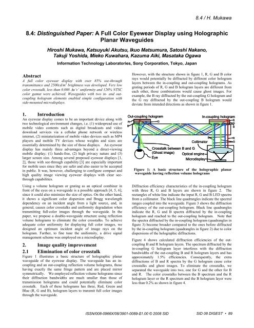
<strong>8.4</strong> / H. Mukawa<br />
<strong>8.4</strong>: <strong>Distinguished</strong> <strong>Paper</strong>: A <strong>Full</strong> <strong>Color</strong> <strong>Eyewear</strong> <strong>Display</strong> <strong>using</strong> Holographic<br />
Planar Waveguides<br />
Hiroshi Mukawa, Katsuyuki Akutsu, Ikuo Matsumura, Satoshi Nakano,<br />
Takuji Yoshida, Mieko Kuwahara, Kazuma Aiki, Masataka Ogawa<br />
Information Technology Laboratories, <strong>Sony</strong> Corporation, Tokyo, Japan<br />
Abstract<br />
A full color eyewear display with over 85% see-through<br />
transmittance and 2500cd/m 2 brightness was developed. Very low<br />
color crosstalk, less than 0.008 Δu’v’ uniformity and 120% NTSC<br />
color gamut were achieved. Waveguides with two in- and outcoupling<br />
hologram elements enabled simple configuration with<br />
side-mounted microdisplays.<br />
1. Introduction<br />
An eyewear display comes to be an important device along with<br />
two technological environment changes, i.e. (1) widespread use of<br />
mobile video contents such as digital broadcasts and video<br />
download services via a cellular phone network or wireless<br />
internet, (2) miniaturization of mobile video devices such as MP4<br />
players and mobile TV devices whose weights and sizes are<br />
essentially determined by the size of those displays. An eyewear<br />
display has mainly three advantages beyond a direct-viewing<br />
mobile display; (1) hands-free, (2) high privacy nature and (3)<br />
larger screen size. Among several proposed eyewear displays [1,<br />
2], those with see-through capability [3] are especially important<br />
for mobile uses since they are safer and also easier to be accepted<br />
in public. It was, however, challenging to configure compact and<br />
high quality image viewing eyewear displays with clear seethrough<br />
capabilities.<br />
Using a volume hologram or grating as an optical combiner in<br />
front of the eyes on a waveguide is a possible approach [4, 5, 6],<br />
since it could also minimize the size of optics. On the other hand,<br />
it shows a significant color dispersion and Bragg wavelength<br />
dependency on an incident angle from a light source, and, in<br />
general, causes color crosstalks and uniformity degradation when<br />
transmitting full-color images through the waveguide. In the<br />
paper, we propose a double-waveguide structure <strong>using</strong> reflection<br />
volume holograms to eliminate the color crosstalks. To achieve<br />
adequate color uniformity for displaying full color images, we<br />
designed an optimum incident angle of image rays on the<br />
hologram. Further, to fine tune the uniformity, a drive signal<br />
management scheme was employed on a microdisplay.<br />
2. Image quality improvement<br />
2.1 Elimination of color crosstalk<br />
Figure 1 illustrates a basic structure of holographic planar<br />
waveguide of the eyewear display. The waveguide has an incoupling<br />
and an out-coupling reflection volume holograms, those<br />
having exactly the same fringe pattern and are placed mirror<br />
symmetrically. We employed reflection volume holograms since<br />
their diffraction bandwidths are much smaller than those of<br />
transmission holograms and could potentially eliminate color<br />
crosstalk. Each of these holograms has three, Red, Green and<br />
Blue (R, G and B), hologram layers to transmit full color images<br />
through the waveguide.<br />
However, with the structure shown in figure 1, R, G and B color<br />
rays would potentially be diffracted by different color hologram<br />
layers between the in-coupling and out-coupling holograms. As<br />
grating periods of R, G and B hologram layers are different from<br />
each other, those combinations would cause ghost images. For<br />
example, the B ray diffracted by the out-coupling G hologram and<br />
the G ray diffracted by the out-coupling B hologram would<br />
deviate from intended directions as shown in figure 1.<br />
Out-coupling hologram<br />
R<br />
B<br />
ISSN/008-0966X/08/3901-0089-$1.00 © 2008 SID<br />
G<br />
Collimator<br />
Crosstalk between B and G<br />
(Ghost image) Optical engine<br />
Eye<br />
Microdisplay<br />
In-coupling hologram<br />
Figure 1: A basic structure of the holographic planar<br />
waveguide having reflection volume holograms<br />
Diffraction efficiency characteristics of the in-coupling hologram<br />
with three R, G and B layers are shown in figure 2. The<br />
rectangles of white line indicate the input R, G and B LED spectra<br />
from a collimator. The black line quadrangles indicate the spectral<br />
ranges coupled into the waveguide. Figure 3 shows the diffraction<br />
efficiency of the out-coupling hologram. Black line quadrangles<br />
indicate the R, G and B spectra diffracted by the in-coupling<br />
hologram and reached to the out-coupling hologram. Note that<br />
the spectra diffracted by the in-coupling hologram (quadrangles in<br />
figure 3) become broader compared to the ones before diffracted<br />
by the in-coupling hologram (quadrangles in figure 2) due to color<br />
dispersions of the holographic diffractions.<br />
Figure 4 shows calculated diffraction efficiencies of the outcoupling<br />
B and R hologram layers. The spectrum diffracted by the<br />
in-coupling G hologram layer interferes with the diffraction<br />
bandwidths of the out-coupling B and R hologram layers and has<br />
approximately 1.5% efficiencies. Consequently, the extra<br />
diffractions of B and R spectra by the G hologram cause color<br />
crosstalks and ghost images. To eliminate the crosstalks, we<br />
separated the waveguide into two, one for G and the other for B<br />
and R. The color crosstalks between the B spectrum and the R<br />
hologram layer or the R spectrum and the B hologram layer were<br />
less than 0.2% as shown in figure 4.<br />
B<br />
SID 08 DIGEST • 89<br />
R<br />
G<br />
B<br />
R<br />
G
<strong>8.4</strong> / H. Mukawa<br />
Wavelength (μm)<br />
Figure 2: Diffraction efficiencies of R, G and B hologram<br />
layers of the in-coupling hologram. The thicknesses and index<br />
modulations of each hologram layer were approximately 5μm<br />
and 0. 04 respectively.<br />
Wavelength Wavelength (μm) (μm)<br />
Input blue spectrum<br />
A<br />
Coupled in red spectrum<br />
Input green spectrum<br />
Coupled in blue spectrum<br />
Coupled in green spectrum<br />
A<br />
Input red spectrum<br />
Incident angle to the in-coupling hologram (degree)<br />
Incident angle to the out-coupling hologram (degree)<br />
Figure 3: Diffraction efficiencies of R, G and B hologram<br />
layers of the out-coupling hologram. The thicknesses and<br />
index modulations of each hologram layer were<br />
approximately 2μm and 0.035 respectively.<br />
2.2 Improvement of color uniformity<br />
Another issue to achieve high color image quality is the<br />
uniformity through out the field of view (FOV). A Bragg<br />
diffraction wavelength (Bragg λ) varies by an incident angle of a<br />
ray to a hologram. Therefore, each R, G and B color spectrum<br />
profile changes depending on the specific angle (the field viewing<br />
angle) within the FOV. The peak wavelengths of R, G and B<br />
spectra become shorter at the in-coupling hologram side of the<br />
field. To reduce the spectrum shift within the entire FOV, we<br />
employed two approaches. One is to have oblique in and out<br />
optical axes layout on the waveguide and the other is to employ a<br />
drive signal management of the microdisplay.<br />
90 • SID 08 DIGEST<br />
Diffraction efficiency (%)<br />
Diffraction efficiency (%)<br />
Diffraction efficiency (%)<br />
0.2%<br />
Blue diffraction<br />
efficiency<br />
Blue spectrum Green spectrum Red spectrum<br />
Wavelength (μm)<br />
Red diffraction<br />
efficiency<br />
B spectrum diffracted<br />
by the R hologram<br />
G spectrum diffracted<br />
by the B hologram<br />
G spectrum diffracted<br />
by the R hologram<br />
R spectrum diffracted<br />
by the B hologram<br />
Figure 4: Diffraction efficiencies of the out-coupling B and R<br />
hologram layers at an incident angle of -50°. (A cross section<br />
A-A in Figure. 3) The incident R, G and B spectral ranges<br />
on the out-coupling hologram are also shown.<br />
2.2.1 Oblique optical axis layout on the incoupling<br />
hologram<br />
Amount of a Bragg λ shift (the difference between the Bragg<br />
wavelengths at both ends of a given FOV) depends on a designed<br />
light incident angle on a hologram. When a ray C enters the<br />
hologram, a Bragg wavelength λc is given by the Bragg condition,<br />
λc = 2 n Λ Sin θB (1)<br />
θB is an angle between the ray C and a fringe of the hologram,<br />
Λ is a fringe period and n is an index of the hologram as shown in<br />
figure 5. A λc change by θB could be obtained by differentiating<br />
the equation (1) to derive equation (2).<br />
δλc/δθB = 2 n Λ Cos θB (2)<br />
Bragg condition also satisfies the following equation (3).<br />
θB = (θs –θr)/2 (3)<br />
θr is an incident angle on a hologram and θs is a diffraction angle<br />
of the ray C.<br />
λC<br />
C<br />
λRGB<br />
θB<br />
Λ<br />
θr<br />
θs<br />
n<br />
Figure 5: A geometry of the Bragg condition
From the equation (2) and (3), the δλc/δθ B could be minimized<br />
when θs –θr was close to 180°. It indicates that the Bragg λ shift<br />
could be reduced if the incident ray on the in-coupling hologram<br />
was slanted towards diffracted rays. Consequently, we slanted<br />
the optical axis of the microdisplay and collimator (the optical<br />
engine) by 10° against the in-coupling hologram, as shown in<br />
figure 6.<br />
Out-coupling hologram<br />
R<br />
B<br />
G<br />
R<br />
B<br />
G<br />
Collimator<br />
Optical engine<br />
Eye Microdisplay<br />
Figure 6: An oblique layout between the waveguide and<br />
the optical engine<br />
As a result, the Bragg λ disparity between both ends of the FOV<br />
reduced from 45nm to 37nm and the color gamut improved from<br />
76% to 120% compared to the NTSC standard as shown in figure<br />
7. The improved color gamut was confirmed within the common<br />
area of color reproduction areas for -8° through +8° field viewing<br />
angle in an u’v’ diagram. We used R, G and B LEDs to illuminate<br />
the microdisplay and each of the peak wavelengths was 640nm,<br />
525nm and 450nm respectively.<br />
v´<br />
0.5<br />
0.4<br />
0.3<br />
0.2<br />
0.1<br />
(1) 0˚ incident angle<br />
In-coupling hologram<br />
10°<br />
Common area=76 % of NTSC gamut<br />
0<br />
0 0.1 0.2 0.3 0.4 0.5 0.6<br />
u´<br />
NTSC<br />
sRGB<br />
R<br />
B<br />
G<br />
v´<br />
0.5<br />
0.4<br />
0.3<br />
0.2<br />
0.1<br />
(2) 10˚ incident angle<br />
<strong>8.4</strong> / H. Mukawa<br />
Figure 7: <strong>Color</strong> gamut at two different incident angles<br />
on the in-coupling hologram<br />
2.2.2 Drive signal management of microdisplay<br />
The final approach to improve color uniformity is controlling a<br />
drive signal of the microdisplay. If there is no color signal<br />
management, a white position in the diagram moves more than<br />
0.045 Δu’v’, depending on a field viewing angle from -8° through<br />
+8 ° as shown in figure 8. The scheme is similar to that of<br />
projection displays. Our system requires only one-dimensional<br />
control along the diffraction direction, while projection displays<br />
usually require two-dimensional control. The basic signal process<br />
is to multiply compensation matrices by original drive signals (Ri,<br />
G i, B i) to obtain new signals (R’ i, G’ i, B’ i) which could display<br />
uniform chromaticity at any field viewing angle as expressed by<br />
the equation (4) .<br />
⎛ R'<br />
i ⎞<br />
⎜ ⎟<br />
⎜G'<br />
i⎟<br />
⎜ ⎟<br />
⎝ B'<br />
i ⎠<br />
=<br />
⎛αR<br />
⎜<br />
⎜ βR<br />
⎜<br />
⎝ γR<br />
− i<br />
− i<br />
− i<br />
α<br />
β<br />
γ<br />
G − i<br />
G − i<br />
G − i<br />
α<br />
β<br />
γ<br />
B − i<br />
B − i<br />
B − i<br />
⎞<br />
⎟<br />
⎟<br />
⎟<br />
⎠<br />
⎛ Ri<br />
⎞<br />
⎜ ⎟<br />
⎜Gi<br />
⎟<br />
⎜ ⎟<br />
⎝ Bi<br />
⎠<br />
αR − i is a compensation coefficient which is multiplied by<br />
original drive signal Ri to obtain compensated red drive signal R’ i<br />
β is one which is multiplied by original drive signal R i<br />
and R − i<br />
Common area =120% of NTSC gamut<br />
0<br />
0 0.1 0.2 0.3 0.4 0.5 0.6<br />
u´<br />
to obtain compensated green drive signal G’ i, for example. The “i”<br />
means the specific position in the displayed image along the<br />
diffraction direction.<br />
(4)<br />
NTSC<br />
sRGB<br />
SID 08 DIGEST • 91
<strong>8.4</strong> / H. Mukawa<br />
The experimental data of how the color uniformity was improved<br />
by our drive signal management is also shown in figure 8. Δu’v’<br />
decreased from over 0.045 to less than 0.008 which was sufficient<br />
for eyewear displays.<br />
Δu'v'<br />
0.05<br />
0.04<br />
0.03<br />
0.02<br />
0.01<br />
0<br />
-8 -6 -4 -2 0 2 4 6 8<br />
Field angle (deg ree)<br />
Figure 8: <strong>Color</strong> differences before and after the drive<br />
signal management<br />
3. Conclusion<br />
We have developed a see-through full color eyewear display <strong>using</strong><br />
holographic elements on planar waveguides (Figure 9). 120%<br />
NTSC color gamut, less than 0.008 Δu’v’ color uniformity and<br />
over 2500cd/m 2 brightness were achieved with a 20° diagonal<br />
FOV. The advantages of the display are over 85% see-through<br />
transmittance and simply-structured waveguides suitable for<br />
eyewearable devices. The waveguide was a 1.4mm thick glass<br />
substrate with volume reflection holograms placed in mirror<br />
symmetry. In the future, glass substrates could be replaced with<br />
plastic substrates to make them lighter and more robust to expand<br />
applicable fields.<br />
92 • SID 08 DIGEST<br />
before compensation<br />
after compensation<br />
Figure 9: A photograph of the prototype<br />
4. References<br />
[1] J. E. Melzer and K. Moffit, “Head Mounted <strong>Display</strong>s”,<br />
(McGraw Hill, 1997), ISBN 0070418195<br />
[2] H. Mukawa et al., “Novel Virtual Image Optics for<br />
Reflective Microdisplays”, 2000 IDRC Digest, pp96-99,<br />
2000<br />
[3] Y. Amitai, “A Two-Dimensional Aperture Expander for<br />
Ultra-Compact, High-Performance Head-Worn <strong>Display</strong>s”,<br />
2005 SID International Symposium Digest, pp360-363, 2005<br />
[4] Y. Amitai, S. Reinhom and A.A.Friesem, “Visor-display<br />
design based on planar holographic optics”, Appl. Opt. 34,<br />
1352-6, 1995<br />
[5] I. Kasai et al., “Actually wearable see-through display <strong>using</strong><br />
HOE”, ODF 2000, pp117-120, 2000<br />
[6] T. Levola, “Diffractive optical components for near to<br />
eye displays”, 2006 SID International Symposium<br />
Digest, pp64-67, 2006