Volume Control Dampers Remotely Operated Balancing Dampers ...
Volume Control Dampers Remotely Operated Balancing Dampers ...
Volume Control Dampers Remotely Operated Balancing Dampers ...

Create successful ePaper yourself
Turn your PDF publications into a flip-book with our unique Google optimized e-Paper software.
For Models C/FSX (See Fig. 1, Page 1)<br />
Damper is supported directly by the grid system and may lay on top<br />
of perforated metal (or similar) grille core material Skirt material must<br />
overhang the Tee bars around perimeter of damper.<br />
American Made. World Proven.<br />
Ceiling Radiation <strong>Dampers</strong> Installation Instructions<br />
Models Covered by These Instructions: C-RD(-A), C-RD-T(-A/T), C-S/R(-A), C/FS(-2F),<br />
C/FSB, C/FSX(-2F), C/FSR-1, C/FSR-2, C/D-P<br />
Item/Description<br />
1.Grille Frame (Steel)<br />
2.Diffuser or Grille Core (Metallic or Non-Metallic)<br />
3.Sheet Metal Duct<br />
4.#8 Sheet Metal Screw<br />
5.Ceiling Radiation Damper<br />
6.16 MSG X 1-1/2” Channel<br />
7.Ceiling Grid (UL Classified)<br />
8.Duct Drop<br />
9.12 SWG Steel Wire<br />
10.Acoustical Lay-In Panels (UL Classified)<br />
11.Rigid Gypsum/Drywall Wall Board Ceiling (UL Classified)<br />
12.Thermal Blanket, CK-2000-1 (-B)<br />
Hinge Door Applications (Figure 3)<br />
For Model C/D-P Ceiling radiation damper is the same size as<br />
the ceiling opening and installs directly into the exposed Tee<br />
bar grid system opening. Damper is supported directly by the<br />
grid system and may lay on top of perforated metal (or similar)<br />
grille core material Fusible Link support wire must attach to<br />
duct or ceiling supports above.<br />
<strong>Dampers</strong> Supported By Ductwork Above<br />
Note: When main ducts are supported by 16 ga. x 1-1/2” steel<br />
channels (with 9/16” minimum flanges) located 1” to 3” from<br />
and on both sides of a steel duct drop and these channels are<br />
suspended by #12 SWG wire from structure above. The steel<br />
duct drop provides all required support for ceiling damper and<br />
grilles. Air diffuser flange must overlap the ceiling membrane<br />
by a minimum of one inch.<br />
Follow guidelines on Page 1 when preparing opening in the<br />
ceiling membrane and making connections.<br />
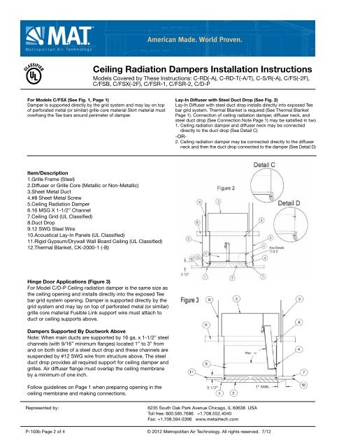
Lay-In Diffuser with Steel Duct Drop (See Fig. 2)<br />
Lay-In Diffuser with steel duct drop installs directly into exposed Tee<br />
bar grid system. Thermal Blanket is required (See Thermal Blanket<br />
Page 1). Connection of ceiling radiation damper, diffuser neck, and<br />
steel duct drop (See Connection Note Page 1) may be satisfied in two<br />
1. Ceiling radiation damper and diffuser neck may be connected<br />
directly to the duct drop (See Detail C)<br />
-OR-<br />
2. Ceiling radiation damper may be connected directly to the diffuser<br />
neck and then the duct drop connected to the damper (See Detail D)<br />
Figure 3<br />
Represented by: 6235 South Oak Park Avenue Chicago, IL 60638 USA<br />
Toll free: 800.585.7686 +1.708.552.4040<br />
Fax: +1.708.594.0396 www.metairtech.com<br />
P-100b Page 2 of 4 © 2012 Metropolitan Air Technology. All rights reserved. 7/12