Rendering 3D Volumes Using Per-Pixel Displacement ... - Eric Risser
Rendering 3D Volumes Using Per-Pixel Displacement ... - Eric Risser
Rendering 3D Volumes Using Per-Pixel Displacement ... - Eric Risser

You also want an ePaper? Increase the reach of your titles
YUMPU automatically turns print PDFs into web optimized ePapers that Google loves.
Abstract<br />
<strong>Rendering</strong> <strong>3D</strong> <strong>Volumes</strong> <strong>Using</strong> <strong>Per</strong>-<strong>Pixel</strong> <strong>Displacement</strong> Mapping<br />
<strong>Rendering</strong> <strong>3D</strong> <strong>Volumes</strong> <strong>Using</strong> <strong>Per</strong>-<strong>Pixel</strong> <strong>Displacement</strong> Mapping offers<br />
a simple and practical solution to the problem of seamlessly<br />
integrating many highly detailed <strong>3D</strong> objects into a scene without<br />
the need to render large sets of polygons or introduce the overhead<br />
of an obtrusive scene-graph. This work takes advantage of modern<br />
programmable GPU’s as well as recent related research in the<br />
area of per-pixel displacement mapping to achieve view independent,<br />
fully <strong>3D</strong> rendering with per-pixel level of detail. To achieve<br />
this, a box is used to bound texture-defined volumes. The box acts<br />
as a surface to which the volume will be drawn on. By computing<br />
a viewing ray from the camera to a point on the box and using that<br />
point as a ray origin, the correct intersection with the texture volume<br />
can be found using various per-pixel displacement mapping<br />
techniques. Once the correct intersection is found, the final color<br />
value for the corresponding point on the box can be computed. The<br />
technique supports various effects taken both from established raycasting<br />
and ray-tracing methods such as reflection, refraction, selfshadowing<br />
on models, a simple animation scheme and an efficient<br />
method for finding distances through volumes.<br />
Keywords: per-pixel displacement mapping, image based rendering,<br />
impostor rendering, volumetric rendering<br />
∗ e-mail: erisser@cs.ucf.edu<br />
<strong>Eric</strong> <strong>Risser</strong> ∗<br />
University of Central Florida<br />
1 Introduction<br />
Image based techniques have eclipsed all others as a practical<br />
means of adding profuse, highly detailed objects to an environment<br />
during real-time rendering. <strong>Using</strong> conventional methods to achieve<br />
this goal would require the use of huge sets of polygons to be rendered<br />
as well as the extra overhead necessary to manage the added<br />
scene complexity. Among the proposed alternatives, the impostor<br />
method is at the forefront. An impostor is a two dimensional image<br />
which is rendered onto a billboard. When incorporated into a scene<br />
the billboard is meant to replace highly detailed geometry. Impostors<br />
are pre-computed and stored in memory or they are generated<br />
in real-time. In either case an impostor is only accurate for a specific<br />
viewing direction. In practical implementations an accuracy<br />
threshold is given. As the viewing direction changes the accuracy<br />
of the impostor diminishes. Once the threshold is passed, the image<br />
is replaced with a new image which is accurate in terms of the new<br />
viewing direction.<br />
This technique utilizes modern programmable graphics hardware in<br />
order to achieve accurate geometric reproductions of <strong>3D</strong> models for<br />
any given viewing angle. It improves True Impostors [<strong>Risser</strong>. 2007]<br />
as well as builds off of and relies heavily on concepts laid out in Relief<br />
Mapping of Non-Height Field Surfaces [Policarpo et al. 2006]<br />
and Parallax Occlusion Mapping [Tatarchuk. 2006]. <strong>Rendering</strong> <strong>3D</strong><br />
<strong>Volumes</strong> <strong>Using</strong> <strong>Per</strong>-<strong>Pixel</strong> <strong>Displacement</strong> Mapping distinguishes itself<br />
from previous per-pixel displacement mapping impostor methods<br />
in two major areas.
1. By contributing a technique for rendering a texture volume<br />
onto the three visible faces of a box, not only breaking free<br />
of restrictions on the viewing direction but also achieving true<br />
volumetric rendering.<br />
2. By offering an alternative composition for texture-defined<br />
volumes, allowing for a larger possibility of potential shapes<br />
to be stored and rendered with no additional overhead.<br />
2 Background<br />
Parallax mapping [Kaneko et al. 2001] is a method for approximating<br />
the parallax seen on uneven surfaces. <strong>Using</strong> the view ray transformed<br />
to tangent space, parallax mapping samples a height texture<br />
to find the approximate texture coordinate offset that will give the<br />
illusion that a three dimensional structure is being rendered. Parallax<br />
mapping is a crude approximation of displacement mapping. It<br />
cannot simulate occlusion, self shadowing or silhouettes. Since it<br />
requires only one additional texture read, it is a fast and therefore<br />
relevant approximation for use in video games.<br />
View dependent displacement mapping [Wang et al. 2003a] takes<br />
a bi-directional texture function (BTF) approach to per-pixel displacement<br />
mapping. This approach, much like impostors involves<br />
pre-computing for each potential view direction an additional texture<br />
map of the same dimensions as the source texture. The goal<br />
of this method is to store the distance from the surface of our polygon<br />
to the imaginary surface that is being viewed. The method<br />
stores a five-dimensional map indexed by three position coordinates<br />
and two angular coordinates. The pre-computed data is then compressed<br />
and decompressed at runtime on the GPU. This method<br />
produces good visual results but requires significant preprocessing<br />
and storage to operate.<br />
Relief mapping [Policarpo et al. 2005] can be considered an extension<br />
of parallax mapping. Rather than a coarse approximation to<br />
the solution, relief mapping performs a linear search or ”ray march”<br />
along the view ray until it finds a collision with the surface, at which<br />
point a binary search is used to locate the exact point of intersection.<br />
Shell texture functions [Chen et al 2004], much like relief mapping<br />
attempts to render the subsurface details of a polygon. However,<br />
unlike relief mapping, which restricts itself to finding a new,<br />
more detailed surface, shell texture functions attempts to ray trace a<br />
complex volumetric data set. Shell texture functions produce highquality<br />
visual results by accounting for sub-surface scattering. This<br />
technique is notable due to the hybridization it attempts between<br />
rasterization and ray tracing. It is, however, not viable for many<br />
applications in the graphics community due to long pre-processing<br />
times and a non-interactive frame rate.<br />
Relief mapping of non-linear height-fields [Policarpo et al. 2006]<br />
extends the concepts laid out in relief mapping by adding multiple<br />
height-field data into the problem, creating distinct volumes.<br />
The authors present an efficient method for determining whether<br />
the view ray passes through one of these volumes.<br />
Practical Dynamic Parallax occlusion mapping [Tatarchuk. 2006]<br />
offers an alternative per-pixel displacement mapping solution. Similar<br />
to relief mapping, a linear search is performed. Then a single<br />
iteration of the secant method is used to fit a series of discrete<br />
linear functions to the curve. This achieves a high rendering<br />
speed by eliminating the need for branch dependent texture<br />
lookups. Whereas the single iteration of the secant method does not<br />
achieve the same level of accuracy as a true root finding method. in<br />
practice there is very little rendering error, making this technique<br />
suitable for real-time applications.<br />
In True Impostors [<strong>Risser</strong>. 2007] a single texture can hold four<br />
height-fields which can represent many volumes. It is possible to<br />
add more texture data and extend this to any shape. This is illustrated<br />
in Figure 2 where the image of a fish is defined by multiple<br />
height-fields stored in a four-channel texture. This texture is shown<br />
in image c where the red and blue color channels are each used to<br />
store a height-field. Since the fish is a simple shape, it can be defined<br />
by only two height-fields therefore the remaining two channels<br />
are set to 1 as default. Images a and b show the <strong>3D</strong> representation<br />
of the texture function from image c projected into texture<br />
coordinate space as a volume. More specifically, image a shows<br />
that our algorithm transforms a billboard’s texture coordinates into<br />
a <strong>3D</strong> plane and rotates this plane around the texture volume. Image<br />
b shows the perspective of the texture volume which would be<br />
displayed on the billboard.<br />
Figure 1: Visual representation of a quad’s texture coordinates<br />
transformed into a <strong>3D</strong> plane and rotated around the origin (a) the<br />
corresponding image it produces (b) and the texture used to define<br />
the fish shape (c).<br />
Traditionally, in previous per-pixel displacement mapping techniques<br />
such as Relief Mapping of Non Height Field Surfaces [Policarpo<br />
et al. 2006], these height-fields would represent the surface<br />
of a polygon, and the viewing vector would be transformed into the<br />
polygon’s local coordinate frame with respect to its normal. However,<br />
in this case the surface geometry and texture coordinates are<br />
transformed with respect to the view direction; in other words, a<br />
billboard is generated which can then be used as a window to view<br />
the height fields from any given direction.<br />
2.1 <strong>Per</strong>-<strong>Pixel</strong> <strong>Displacement</strong> Mapping Review<br />
All of the methods presented as background, as well as True Impostors,<br />
can be classified under per-pixel displacement mapping. It<br />
is crucial that the reader have a solid grasp of this type of problem.<br />
By its definition, the goal of per-pixel displacement mapping is to<br />
displace or move a pixel from one point on the screen to another in<br />
much the same way traditional vertex based displacement mapping
displaces the position of a vertex. This is a simple concept which<br />
becomes difficult to implement due to the nature of rasterization and<br />
the design of modern GPUs which has no mechanism for writing a<br />
target pixels color value to a different pixel on the screen. Thus<br />
a wealth of techniques have been proposed to solve this problem.<br />
Generally, when defining the color for a pixel two factors must be<br />
taken into account: the color of the material of the surface at that<br />
pixel and the amount of light being reflected towards the viewer.<br />
Texture maps are the data structure that tends to store all of this<br />
information, either as color or normal values. Therefore, a practical<br />
version of our earlier problem becomes how we can, for our current<br />
pixel, find new texture coordinates that correspond to the point the<br />
target pixel is actually representing.<br />
To solve this problem, the view vector needs to be known from the<br />
camera to each pixel and transformed to texture space using the<br />
polygons normal and tangent as well as the true topology of the<br />
object that is being drawn. The topology can take on many forms<br />
stored in many ways. For simplicity, a single height-field texture is<br />
used to define the true shape of the surface in figure 1.<br />
Figure 2: View ray penetrating Geometry and corresponding<br />
height-field.<br />
Because the view ray projects itself as a line across the surface of<br />
our polygon, it effectively takes a 1D slice out of the 2D function,<br />
clarifying our problem to its true form. We must find the first intersection<br />
of a ray with an arbitrary function. Once this intersection<br />
has been found, the corresponding texture coordinates can be used<br />
to find the desired color for the pixel.<br />
3 Method<br />
Multiple options exist with regard to storing the volume to be rendered.<br />
A four-channel texture is the data structure used in this<br />
technique; therefore, the model is rendered to a texture as a preprocessing<br />
step. Although the texture can be organized in many<br />
possible ways which might lend themselves to specific shapes, two<br />
general schemes are presented in this paper which offer a practical<br />
solution for storing most shapes with the least amount of texture<br />
data needed.<br />
The first, planar mapping, is effective for many shapes. As the name<br />
suggests, the model is reduced to a set of height-maps stacked over<br />
each other on the same plane (shown in Figure 1 c), where the two<br />
height-maps are stored in the red and green color channels of a<br />
single texture while the remaining two channels are set to one by<br />
default. This method for representing volumes was first introduced<br />
in Relief Mapping of Non-Linear Height-Fields [Policarpo et al.<br />
2006] and used again in True Impostors [<strong>Risser</strong>. 2007].<br />
The second method uses a cube map to produce a spherical height<br />
field around an origin point. By rendering an environment map of<br />
depth values from the center of a model to its surface, a volume is<br />
defined. Multiple surfaces are stored in the multiple channels of the<br />
texture map; figure 3 illustrates this process.<br />
Figure 3: The camera is placed at the origin of the model. For each<br />
of the six faces, a height map is rendered which stores the distance<br />
from the origin to the surface of the mesh.<br />
As opposed to an impostor which relies on the use of billboards, this<br />
technique utilizes a box as the primary rendering surface offering<br />
several advantages over the previous technique. Because a billboard<br />
is a flat plane which rotates around its center, volumes can only be<br />
viewed from within when the camera is looking towards the center<br />
of the billboard. This deficiency leaves impostor methods ill-suited<br />
for rendering volumetric data such as clouds and other participating<br />
media. By using a box as the drawing surface and rendering only<br />
the back-faces, no matter where the camera is within or without the<br />
object, geometry will be in view for rendering, as shown in Figure<br />
4.<br />
Figure 4: Box geometry completely bounds the asteroid.<br />
<strong>Per</strong>formance concerns also favor the use of a box instead of a billboard.<br />
Note that a billboard consists of two polygons whereas a box<br />
consists of twelve. Although more geometry is processed when using<br />
a box, the box can tightly bound the volume on three axes. This<br />
is preferable, as the rendering algorithm is fill rate dependent and<br />
the reduction in empty pixels is greatly reduced. Figure 5 illustrates<br />
this by showing side by side a fish model bound by both a<br />
box as discussed in this paper, and a billboard as recommended by
True Impostors [<strong>Risser</strong>. 2007]. It is clear that fewer empty pixels<br />
are drawn using the box method. This is true for any object other<br />
than a sphere, and the benefits of using a box become greater as the<br />
target object becomes elongated in any given direction.<br />
Figure 5: (left) fish model drawn on a box, (right) same fish model<br />
drawn on a billboard.<br />
Now that the benefits behind the box method have been discussed,<br />
an efficient algorithm for rendering volumetric impostors within a<br />
box will be given.<br />
The bulk of this technique operates solely in the pixel pipeline of<br />
the GPU. Once the model has been stored as a texture and a box<br />
mesh has been set up, the vertex processor begins the rendering<br />
process by transforming the vertices positions into world space and<br />
creating for each vertex a view ray which passes from the camera<br />
in world space to each vertex, as shown in Figure 6. Each vertex<br />
also contains an origin point which is best described as a second<br />
(x,y,z) position value which is local to the box itself where each<br />
value takes on either a 1 or a -1 and therefore centers on the origin.<br />
Figure 6: View rays are shown pointing away from the camera;<br />
values are given for each vertex’s origin point.<br />
Rasterization interpolates the view ray and origin point across each<br />
pixel comprising the box. Recall that the back faces of the box<br />
are the rendering surface. Thus, the view ray must be negated so<br />
that it points inwards toward the volume. In most cases, the first<br />
intersection with the volume needs to be found, not the last. Thus,<br />
it is necessary to displace the origin point from the back of the box<br />
to the front along the view ray. This is done in the pixel shader.<br />
Figure 7: Efficient method for finding the intersection with a point<br />
on a box.<br />
Given the origin point (x, y) and the view vector (dx, dy) in this<br />
two dimensional example, the method for finding the closest point<br />
of intersection inside a box is to treat each axis independent of the<br />
other and find the displacement along that axis from the origin point<br />
to the bounding planes set to 1 and -1. Keep in mind that the view<br />
vector is a normalized vector; so by dividing the displacement along<br />
an axis by the same axial component of the vector, a scalar will be<br />
produced which will stretch the view vector to the point of intersection,<br />
this equation is shown in Figure 7. Also note that since texture<br />
space is a cube, whatever scaling is multiplied to the box in world<br />
space, the same scaling must be divided from the view vector in<br />
texture space. Keep in mind that intersections occurring in the opposite<br />
direction from where the view vector is pointing will result in<br />
a negative scalar, thus the correct scalar is the maximum of the two<br />
values. Once each axis has been tested independently, it is a simple<br />
matter to find the minimum of the multiple values, being the other<br />
intersection lying on the surface of the box. The new point can be<br />
found by multiplying the scalar with the view vector and adding the<br />
result back into the origin point. Once the correct origin point is<br />
found, negate the view vector once again so that it is pointing away<br />
from the camera and back towards the volume.<br />
At this point, world space and the box mesh are no longer concerns;<br />
the problem has been reduced to finding the point of intersection between<br />
a ray and a volume, the volume being stored in a texture and<br />
the ray being defined by the view vector and origin point. Various<br />
ray-casting and ray-tracing techniques have been developed to solve<br />
this problem in multiple ways for numerous material properties.<br />
For opaque objects, ray-casting is the most efficient method for<br />
quickly finding the point of intersection. The archetype technique<br />
for this case was introduced in Relief Mapping of Non-Height-Field<br />
Surface Details [Policarpo et al. 2006]. Finding the closest point of<br />
intersection involves a linear followed by binary search, as shown<br />
in Figure 8.<br />
In figure 8, the ray march shows that points along the ray are sampled<br />
at regular intervals. Once a sampled point that lays within the<br />
volume is found, as shown in image a, a binary search repeatedly<br />
halves the remaining interval until the exact point of collision is<br />
found. This is shown in images b-d. Keep in mind that points lying
Figure 8: Streamlined ray-casting method.<br />
on the vector will still take on values within the 1 to -1 range. For<br />
each point tested, it is necessary to do a texture lookup to find the<br />
height-field values. In the case of planar mapping, the values range<br />
from -1 to 1; adding 1 and dividing by 2 will transform all three<br />
axis values so that they lay between 0 and 1, corresponding to the<br />
texture’s UV space. In the case of cube mapping, a vector from the<br />
origin to the test point is used as a lookup into the cube-map.<br />
A limited yet effective animation scheme is offered in which the<br />
animation frames are tiled on a single texture, offering quick lookups<br />
using the pixel shader.<br />
Figure 9: Animated texture map with cooresponding models.<br />
Rather than using the entire texture to store a single model, the image<br />
is partitioned into discrete equally sized regions each storing a<br />
frame of the desired animation, as seen in figure 9. Planar mapping<br />
is shown in this example but any volume representation could be<br />
accommodated. The animation can be looped through by passing<br />
a global time variable into the shader and using it to select the current<br />
target region. This would lend itself nicely for rendering large<br />
herds of animals, schools of fish, and flocks of birds.<br />
4 Results and Analysis<br />
Nearly correct reproductions of geometry are rendered to the inside<br />
surface of a box for any possible viewing direction. This is shown<br />
in figure 10, where multiple dogs are displayed from arbitrary directions.<br />
The use of a box as the rendering surface is favorable in<br />
this instance as the shape of the dog can be tightly bound by the<br />
shape of the box, resulting in both the reduction in empty pixels on<br />
screen at any given time and the number of linear search steps that<br />
need to be tested.<br />
This method performs similarly to other per-pixel displacement<br />
mapping techniques as the same ray-volume intersection algorithms<br />
are shared among them. The main concern unique to this specific<br />
rendition involves excessive overdraw. <strong>Per</strong>formance is fill-rate dependent;<br />
so when objects occlude other objects there is the potential<br />
for the same pixel to be processed multiple times. Every precaution<br />
is taken to avoid this situation. The CPU sorts objects front to<br />
back so that filled pixels will be safe from overdraw. Empty pixels<br />
are still at risk of being processed multiple times as parts of other<br />
boxes. The use of the box limits the number of empty pixels drawn<br />
for each object and keeps this shortcoming in check.<br />
<strong>Using</strong> this method, it is possible to represent more geometry on<br />
screen at once than could be achieved using standard polygonal<br />
means. an example is shown on the first page and in figure 11,<br />
where a model of Jupiter is rendered with a quarter of a million asteroids<br />
forming the ring. The method discussed in this paper was<br />
implemented in C++ using Direct X 9. As stated previously, performance<br />
is fill-rate dependent. Therefore, performance is almost<br />
entirely determined by how many pixels on screen are being drawn<br />
as well as how much overdraw is occurring. Due to the nature of<br />
this bottleneck, frame-rate measurements are somewhat superficial<br />
and can drastically change with the view direction. However, given<br />
ten linear search steps followed by eight binary search steps and<br />
an object which fills up a 640 by 480 window, 180-190 fps was<br />
achieved. In the Jupiter demo, which rendered a quarter of a million<br />
asteroids in a 1024 by 768 window, 30 fps was achieved on<br />
average. Both tests used a GeForce 7800 GT for benchmarking.<br />
5 Discussion<br />
This paper offers an effective and practical technique for generating<br />
staggering amounts of faux-geometry to any rendered environment.<br />
Impostor models are drawn with very little visual error in<br />
comparison with their geometrical counterparts while offering perpixel<br />
level of detail. A multitude of different rendering methods are<br />
possible, offering techniques for animated opaque, reflective and<br />
refractive objects, as well as the ground work for more custom and<br />
potentially sophisticated volumetric rendering techniques such as<br />
participating media.<br />
This paper builds upon the concepts laid out in Relief Mapping of<br />
Non-Height-Field Surface Details [Policarpo et al. 2006] and Parallax<br />
Occlusion Mapping [Tatarchuk. 2006]. It extends upon True<br />
Impostors [<strong>Risser</strong>. 2007] by offering a more efficient, streamlined<br />
as well as robust rendering model. Various schemes are offered<br />
as means to store and retrieve model data in the form of textures
which can be efficiently accessed by the GPU. This method adopts<br />
advantages of both rasterization and ray-tracing, using a hybrid approach<br />
which takes the best each has to offer. This method is ideal<br />
for use in video games as it improves upon the already widely used<br />
imposter concept.<br />
References<br />
BLINN, J. F. 1978. Simulation of wrinkled surfaces. In SIGGRAPH<br />
’78: Proceedings of the 5th annual conference on Computer<br />
graphics and interactive techniques, ACM Press, New York, NY,<br />
USA, 286–292.<br />
CHEN, Y., TONG, X., WANG, J., LIN, S., GUO, B., AND SHUM,<br />
H. 2004. Shell texture functions. In Transaction of Grpahics -<br />
Proceedings of SIGGRAPH 2004 23. 343-352.<br />
COOK, R. L. 1984. Shade trees. In SIGGRAPH ’84: Proceedings<br />
of the 11th annual conference on Computer graphics and interactive<br />
techniques, ACM Press, New York, NY, USA, 223–231.<br />
HART, J. C. 1996. Sphere tracing: A geometric method for the<br />
antialiased ray tracing of implicit surfaces. The Visual Computer<br />
12, 10, 527–545.<br />
HIRCHE, J., EHLERT, A., GUTHE, S., AND DOGGETT, M. 2004.<br />
Hardware accelerated per-pixel displacement mapping. In GI<br />
’04: Proceedings of the 2004 conference on Graphics interface,<br />
Canadian Human-Computer Communications Society, School of<br />
Computer Science, University of Waterloo, Waterloo, Ontario,<br />
Canada, 153–158.<br />
KANEKO, T., TAKAHEI, T., INAMI, M., KAWAKAMI, N.,<br />
YANAGIDA, Y., AND MAEDA, T. 2001. Detailed shape representation<br />
with parallax mapping. In Proceedings of the ICAT<br />
2001, 205–208.<br />
KAUTZ, J., AND SEIDEL, H.-P. 2001. Hardware accelerated displacement<br />
mapping for image based rendering. In GRIN’01: No<br />
description on Graphics interface 2001, Canadian Information<br />
Processing Society, Toronto, Ont., Canada, Canada, 61–70.<br />
KOLB, A., AND REZK-SALAMA, C. 2005. Efficient empty space<br />
skipping for per-pixel displacement mapping. In Proc. Vision,<br />
Modeling and Visualization.<br />
MACIEL, P.W.C., SHIRLEY, P. 1995. Visual navigation fo large<br />
environments using textured clusters. In Proceedings of the 1995<br />
symposium on Interactive <strong>3D</strong> graphics. 95-102.<br />
MAX, N. 1998. Horizon mapping: shadows for bump-mapped<br />
surfaces. In The Visual Computer 4, 2, 109–117.<br />
MCGUIRE, M. 2005. Steep parallax mapping. In I<strong>3D</strong> 2005 Poster.<br />
OLIVEIRA, M. M., BISHOP, G., AND MCALLISTER, D. 2000.<br />
Relief texture mapping. In SIGGRAPH ’00: Proceedings of the<br />
27th annual conference on Computer graphics and interactive<br />
techniques, ACM Press/Addison-Wesley Publishing Co., New<br />
York, NY, USA, 359–368.<br />
PATTERSON, J. W., HOGGAR, S. G., AND LOGIE, J. R. 1991.<br />
Inverse displacement mapping. Comput. Graph. Forum 10, 2,<br />
129–139.<br />
POLICARPO, F., OLIVEIRA, M. M., AND COMBA, J. L. D. 2005.<br />
Real-time relief mapping on arbitrary polygonal surfaces. In<br />
SI<strong>3D</strong> ’05: Proceedings of the 2005 symposium on Interactive<br />
<strong>3D</strong> graphics and games, ACM Press, New York, NY, USA, 155–<br />
162.<br />
POLICARPO, F., OLIVEIRA, M. M. 2006. Relief Mapping of Non-<br />
Height-Field Surface Details. In SI<strong>3D</strong> ’06:ACM SIGGRAPH<br />
2006 Symposium on Interactive <strong>3D</strong> Graphics and Games, Redwood<br />
City, CA, USA, 55–62.<br />
PRESS, W., FLANNERY, B., TEUKOLSKY, S., AND VETTERLING,<br />
W. 2002. Root finding and non-linear sets of equations. In<br />
Numerical Recipes in C, 354–360.<br />
SCHAUFLER, G., AND PRIGLINGER, M. 1999. Horizon mapping:<br />
shadows for bump-mapped surfaces. In Efficient displacement<br />
mapping by image warping, 175–186.<br />
RISSER, E. 2007. True Impostors. In GPU Gems 3.<br />
SLOAN, P., AND COHEN, M., 2000. Interactive horizon mapping.<br />
TATARCHUK. 2006. Dynamic parallax occlusion mapping with<br />
approximate soft shadows. In SI<strong>3D</strong> ’06: Proceedings of the<br />
2006 symposium on Interactive <strong>3D</strong> graphics and games, Redwood<br />
City, California, 63–69.<br />
WALSH. 2003. Parallax mapping with offset limiting. In Infiniscape<br />
Tech Report.<br />
WANG, L., WANG, X., TONG, X., LIN, S., HU, S., GUO, B.,<br />
AND SHUM, H.-Y. 2003. View-dependent displacement mapping.<br />
ACM Trans. Graph. 22, 3, 334–339.<br />
WANG, X., TONG, X., LIN, S., HU, S., GUO, B., AND SHUM,<br />
H.-Y. 2003. Generalized displacement maps. In Eurographics<br />
Symposium on <strong>Rendering</strong>, 227–233.
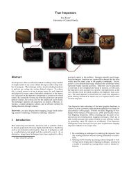
Figure 10: The same box is shown from multiple arbitrary viewing directions.<br />
Figure 11: Various images taken of a real time demo of the technique generating a quarter of a million asteroids.