

True Impostors - Eric Risser
True Impostors - Eric Risser
True Impostors - Eric Risser

Create successful ePaper yourself
Turn your PDF publications into a flip-book with our unique Google optimized e-Paper software.
Abstract<br />
<strong>True</strong> <strong>Impostors</strong> offers an efficient method for adding a large number<br />
of simple models to any scene without having to render a large number<br />
of polygons. The technique utilizes modern shading hardware<br />
to perform ray casting into texture defined volumes. To achieve<br />
this, a virtual screen is set up in texture space for each impostor<br />
and inherits the same camera dependent orientation as the impostor.<br />
Each pixel on the impostor corresponds to a point on its virtual<br />
screen. By casting the viewing ray from this point into our texture<br />
defined volumes, the correct color for the target pixel can be found.<br />
The technique supports self-shadowing on models, reflection, refraction,<br />
a simple animation scheme, and an efficient method for<br />
finding distances through volumes.<br />
Keywords: per-pixel displacement mapping, image based rendering,<br />
impostor rendering, volumetric rendering, refraction<br />
1 Introduction<br />
Most interesting environments, natural as well as synthetic, tend to<br />
be densely populated with many highly detailed objects. Rendering<br />
such an environment would require a huge set of polygons as well<br />
as a sophisticated scene graph and the overhead to run it. As an<br />
alternative, image-based techniques have been explored to offer a<br />
∗ e-mail: erisser@cs.ucf.edu<br />
<strong>True</strong> <strong>Impostors</strong><br />
<strong>Eric</strong> <strong>Risser</strong> ∗<br />
University of Central Florida<br />
practical remedy to the problem. Amongst currently used imagebased<br />
techniques, <strong>Impostors</strong> are a powerful technique that has been<br />
widely used for many years in the graphics community. An impostor<br />
is a two dimensional image rendered onto a billboard which<br />
represents highly detailed geometry. <strong>Impostors</strong> can be generated<br />
in real time or pre-computed and stored in memory, in both cases<br />
the impostor is only accurate for a specific viewing direction, as the<br />
view deviates from this ideal condition, the impostor loses accuracy.<br />
The same impostor is reused until its visual error surpasses a<br />
given arbitrary threshold in which case it is replaced with a more<br />
accurate impostor.<br />
<strong>True</strong> <strong>Impostors</strong> takes advantage of the latest graphics hardware to<br />
achieve accurate geometric representation updated every frame for<br />
any arbitrary viewing angle. It builds off Relief Mapping of Non-<br />
Height Field Surfaces [Policarpo et al. 2006] and Parallax Occlusion<br />
Mapping [Tatarchuk. 2006], extending past the goals of traditional<br />
per-pixel displacement mapping techniques, which are to<br />
add visually accurate sub-surface features to any arbitrary surface<br />
by generating whole 3D objects on a billboard. <strong>True</strong> <strong>Impostors</strong><br />
distinguishes itself from previous per-pixel displacement mapping<br />
impostor methods in two major areas.<br />
1. By contributing a technique for rendering the impostor from<br />
any viewing direction with no viewing limitations or restrictions.<br />
2. Offering a GPU friendly ray tracing scheme designed to work<br />
with per-pixel displacement mapping techniques, opening up<br />
a wealth of potential ray tracing effects such as internal refraction.
2 Background<br />
Parallax mapping [Kaneko et al. 2001] is a method for approximating<br />
the parallax seen on uneven surfaces. Using the view ray transformed<br />
to tangent space, parallax mapping samples a height texture<br />
to find the approximate texture coordinate offset that will give the<br />
illusion that a three dimensional structure is being rendered. Parallax<br />
mapping is a crude approximation of displacement mapping. It<br />
cannot simulate occlusion, self shadowing or silhouettes. Since it<br />
requires only one additional texture read, it is a fast and therefore<br />
relevant approximation for use in video games.<br />
View dependent displacement mapping [Wang et al. 2003a] takes<br />
a bi-directional texture function (BTF) approach to per-pixel displacement<br />
mapping. This approach much like <strong>Impostors</strong> involves<br />
pre-computing for each potential view direction an additional texture<br />
map of the same dimensions as the source texture. The goal<br />
of this method is to store the distance from the surface of our polygon<br />
to the imaginary surface that is being viewed. The method<br />
stores a five-dimensional map indexed by three position coordinates<br />
and two angular coordinates. The pre-computed data is then compressed<br />
and decompressed at runtime on the GPU. This method<br />
produces good visual results but requires significant preprocessing<br />
and storage to operate.<br />
Relief mapping [Policarpo et al. 2005] can be considered an extension<br />
of parallax mapping. Rather than a coarse approximation to<br />
the solution, relief mapping performs a linear search or ”ray march”<br />
along the view ray until it finds a collision with the surface at which<br />
point a binary search is used to home in on the exact point of intersection.<br />
Shell texture functions [Chen et al 2004] much like relief mapping<br />
attempts to render the subsurface details of a polygon. However,<br />
unlike relief mapping, which restricts itself to finding a new,<br />
more detailed surface, shell texture functions attempts to ray trace a<br />
complex volumetric data set. Shell texture functions produce highquality<br />
visual results by accounting for sub-surface scattering. This<br />
technique is notable due to the hybridization it attempts between<br />
rasterization and ray tracing. It is however not viable for many applications<br />
in the graphics community due to long pre-processing<br />
times and a non-interactive frame rate.<br />
Relief mapping of non-linear height-fields [Policarpo et al. 2006]<br />
extends the concepts laid out in relief mapping by adding multiple<br />
height-field data into the problem, creating distinct volumes.<br />
The authors present an efficient method for determining whether<br />
the view ray passes through one of these volumes.<br />
Practical Dynamic Parallax occlusion mapping [Tatarchuk. 2006]<br />
offers an alternative per-pixel displacement mapping solution. Similar<br />
to relief mapping, a linear search is performed. Then a single<br />
iteration of the secant method is used to fit a series of discrete<br />
linear functions to the curve. This achieves a high rendering<br />
speed by eliminating the need for branch dependent texture<br />
lookups. Whereas the single iteration of the secant method does not<br />
achieve the same level of accuracy as a true root finding method, in<br />
practice there is very little rendering error making this technique<br />
suitable for real-time applications.<br />
2.1 Per-Pixel Displacement Mapping Review<br />
All of the methods presented as background as well as <strong>True</strong> <strong>Impostors</strong><br />
can be classified under per-pixel displacement mapping. It is<br />
crucial that the reader have a solid grasp of this type of problem.<br />
By its definition the goal of per-pixel displacement mapping is to<br />
displace or move a pixel from one point on the screen to another in<br />
much the same way traditional vertex based displacement mapping<br />
displaces the position of a vertex. A simple enough concept which<br />
becomes difficult to implement due to the nature of rasterization and<br />
the design of modern GPUs which has no mechanism for writing a<br />
target pixels color value to a different pixel on the screen. Thus<br />
a wealth of techniques have been proposed to solve this problem.<br />
Generally when defining the color for a pixel two factors must be<br />
taken into account, the color of the material of the surface at that<br />
pixel and the amount of light being reflected towards the viewer.<br />
Texture maps are the data structure that tends to store all of this<br />
information, either as color or normal values. Therefore, a practical<br />
version of our earlier problem becomes how can we for our current<br />
pixel, find new texture coordinates that correspond to the point the<br />
target pixel is actually representing.<br />
To solve this problem the view vector needs to be known from the<br />
camera to each pixel, transformed to texture space using the polygons<br />
normal and tangent as well as the true topology of the object<br />
that is being drawn. The topology can take on many forms stored<br />
in many ways, for simplicity, though a single height-field texture is<br />
used to define the true shape of the surface in figure 1.<br />
Figure 1: View ray penetrating Geometry and corresponding<br />
height-field.<br />
Because the view ray projects itself as a line across the surface of<br />
our polygon, it effectively takes a 1D slice out of the 2D function,<br />
clarifying our problem to its true form, finding the first intersection<br />
of a ray with an arbitrary function. Once this intersection has been<br />
found, the corresponding texture coordinates can be used to find the<br />
desired color for the pixel.<br />
3 Method<br />
A single texture can hold four height-fields, which can represent<br />
many volumes. More texture data can be added to extend this to any<br />
shape. Traditionally these height-fields would represent the surface<br />
of a polygon, and the viewing vector would be transformed into the<br />
polygon’s local coordinate frame with respect to its normal. However,<br />
in this case the surface geometry and texture coordinates are<br />
transformed with respect to the view direction, or in other words,<br />
a billboard is generated which can then be used as a window to<br />
view the height fields from any given direction. This is illustrated<br />
in figure 2.
Figure 3: This Illustration walks through the <strong>True</strong> <strong>Impostors</strong> method step-by-step, note that at Cell E two separate directions can be taken<br />
depending on the material type being rendered.<br />
Figure 2: Visual representation of a quads texture coordinates transformed<br />
into a 3D plane and rotated around the origin (left) and the<br />
corresponding image it produces (right).<br />
The right image shows a representation of the billboard’s texture<br />
coordinates after they have been transformed into a 3D plane and<br />
rotated around the functions in the center (represented by the fish).<br />
The left image shows the perspective of the functions which would<br />
be displayed on the billboard.<br />
To expand on this concept please refer to figure 3. In cell A of the<br />
image, the component of this method which operates on geometry<br />
in world space is seen. The camera is viewing a quad which is ro-<br />
tated so that its normal is the vector produced between the camera<br />
and the center of the quad. As shown, texture coordinates are assigned<br />
to each vertex. Cell B reveals texture space, traditionally<br />
a two dimensional space, a third dimension W is added and the<br />
UV coordinates are shifted by -0.5. In cell C the W component of<br />
our texture coordinates are set to 1. Keep in mind that the texture<br />
map only has UV components, so it is bound to two dimensions<br />
and therefore can only be translated along the UV plane, where any<br />
value of W will reference the same point. The texture map although<br />
bound to the UV plane can represent volume data by treating each<br />
of the four variables comprising a pixel as points on the W axis. In<br />
cell D the projection of the texture volume into three dimensional<br />
space is shown. The texture coordinates of each vertex are also rotated<br />
around the origin in the same way as the original quad was<br />
rotated around its origin to produce the billboard. Now the view<br />
ray is introduced into the concept. The view ray is produced by<br />
casting a ray from the camera to each vertex, during rasterization<br />
both the texture coordinates and view rays stored in each vertex are<br />
interpolated across the fragmented surface of the quad. This is conceptually<br />
similar to ray casting/tracing where a viewing screen of<br />
origin points is generated, where each point has a corresponding<br />
vector to define a ray. It should also be noted that each individual<br />
ray projects as a straight line onto the texture map plane and therefore<br />
takes a 2D slice out of the 3D volume to evaluate for collisions.<br />
This is shown in detail in cell E.<br />
Still referring to figure 3, at this point two separate options exist depending<br />
on the desired material type. For opaque objects ray casting<br />
is the fastest and most accurate option available, a streamlined
approach to this has been laid out in Relief Mapping of Non Height<br />
Field Surfaces [Policarpo et al. 2006] using a ray march followed<br />
by binary search as shown in cells F-H. This finds the first point<br />
of intersection into the volume. Due to the nature of GPU design,<br />
it is impractical from an efficiency standpoint to exit out of a loop<br />
early, therefore the maximum number of ray marches and texture<br />
reads must be performed no matter how early in the search the first<br />
collision is found. Rather than ignoring this ”free” data, a method<br />
is proposed to add rendering support for translucent material types<br />
through a localized approximation to ray tracing. Rather than performing<br />
a binary search along the viewing ray, the points along the<br />
W axis are used to define a linear equation for each height field as<br />
shown in cell I. In cell J these linear equations are then tested for<br />
intersection with the view ray in a similar fashion as shown in Parallax<br />
Occlusion Mapping [Tatarchuk. 2006]. The intersection which<br />
falls between the upper and lower bounding points is kept as the<br />
final intersection point. Since the material is translucent the normal<br />
is checked for this point and the view ray is refracted according to<br />
a dielectric value either held constant for the shader or stored in an<br />
extra color channel in one of the texture maps. Once the new view<br />
direction is discovered, the ray march continues and the process is<br />
repeated for any additional surfaces that are penetrated as shown<br />
in cells K-M. By summing the distances traveled through any volume,<br />
the total distance traveled through the model can be known<br />
and used to compute the translucency for that pixel.<br />
<strong>True</strong> <strong>Impostors</strong> also offers a simple yet effective animation scheme<br />
in which the animation frames are tiled on a single texture, offering<br />
quick look-ups using the pixel shader.<br />
Figure 4: Animated texture map with cooresponding models.<br />
Rather than using the entire texture to store a single model, the image<br />
is partitioned into discrete equally sized regions each storing a<br />
frame of the desired animation as shown in figure 4. To accommodate<br />
the new data representation, the UV coordinates stored in each<br />
vertex span the length of a single region as opposed to the entire<br />
texture map. Also, the UV coordinates of the texture map are no<br />
longer shifted by -.5, but shifted so that the middle of the target region<br />
lies on the origin of the coordinate frame. The animation can<br />
be looped through by passing a global time variable into the shader<br />
and using it to select the current target region. This makes <strong>True</strong> <strong>Impostors</strong><br />
a powerful technique for rendering large herds of animals,<br />
schools of fish, and flocks of birds.<br />
4 Results and Analysis<br />
<strong>True</strong> <strong>Impostors</strong> can produce nearly correct reproductions of geometry<br />
on a single billboard for any possible viewing direction. This is<br />
shown in Figure 5 where multiple dogs are displayed from arbitrary<br />
directions. <strong>True</strong> <strong>Impostors</strong> is the first per-pixel displacement mapping<br />
based impostor technique to achieve complete viewing freedom<br />
and thus is the first of such techniques to represent objects in<br />
true 3D.<br />
In addition to viewing independence, this paper tackled a new<br />
volume intersection/traversal method ideal for rendering translucent/refractive<br />
objects which can be applied to any multiple layered<br />
per-pixel displacement mapping technique. Figure 6 shows a glass<br />
sphere rendered using <strong>True</strong> <strong>Impostors</strong> with correct double refraction.<br />
A trace-through of the view vector is also shown to confirm<br />
that <strong>True</strong> <strong>Impostors</strong> is properly rendering the object.<br />
Figure 6: refraction through a glass sphere using <strong>True</strong> <strong>Impostors</strong><br />
Given the lack of a true root finding method during refractive rendering,<br />
<strong>True</strong> <strong>Impostors</strong> suffers from very little error; however, there<br />
is a case where minor artifacts will occur. When entering or leaving<br />
a volume such that one of the linear steps falls on a pixel in<br />
the texture map which does not define the volume being encountered,<br />
there is a chance that the line-segment intersection test can<br />
return a point that also does not lie on a pixel defining the target<br />
volume. The normal of the surface is needed to refract the view ray,<br />
in general this method rarely finds the exact point of intersection,<br />
but since the surface and therefore normal is generally continuous,<br />
the small level of error is unnoticeable by the human eye. However,<br />
at such rare points where a normal not lying on our surface is<br />
returned, the resulting image will show blatant artifacts. To soften<br />
these artifacts, the normal textures are mipmapped so each sampled<br />
point is actually the average of several neighboring points. For<br />
the most part this alleviates the rendering error; this does however<br />
leave a crease where two surfaces meet to form a volume. Because<br />
multiple points on the normal map are averaged, there is no smooth<br />
transition between layers defining a volume as shown in figure 7.<br />
This crease can be remedied through a simple art hack. When generating<br />
the normal maps for each surface, blend the color values<br />
concentrated around the edge of a volume, this should force the<br />
normals to conform at the edge and produce a smooth curve.<br />
In addition to refraction, <strong>True</strong> <strong>Impostors</strong> can also reflect points on<br />
a surface achieving complex local interactions between mirrored
Figure 5: The same impostor is shown from multiple arbitrary viewing directions. <strong>True</strong> <strong>Impostors</strong> is the first technique which has successfully<br />
been able to render view directions which significantly deviate from the profile, as shown in the third and last image.<br />
Figure 7: A visible crease is shown along the intersection of two<br />
surfaces. Due to averaging normal values.<br />
surfaces. As a proof of concept a sphere is rendered using reflection<br />
in figure 8.<br />
Figure 8: Reflective impostor.<br />
The method performs similarly to other per-pixel displacement<br />
mapping techniques; however, there are concerns unique to <strong>True</strong><br />
<strong>Impostors</strong>. Performance is fill-rate dependent. Since billboards can<br />
occlude neighbors it is crucial to perform depth sorting on the CPU<br />
to avoid overdraw. Since <strong>True</strong> <strong>Impostors</strong> is fill-rate dependent, level<br />
of detail is intrinsic, and this is a great asset.<br />
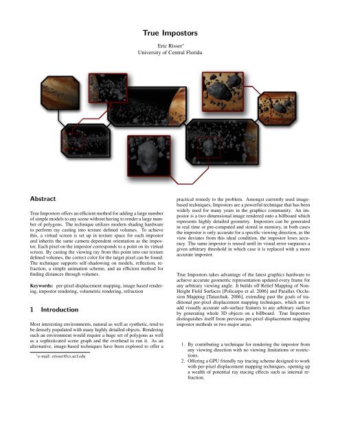
With <strong>True</strong> <strong>Impostors</strong> it is possible to represent more geometry on<br />
screen at once then could be achieved using standard polygonal<br />
means, an example is shown on the first page where a model of<br />
Jupiter is rendered using a quarter of a million asteroids to comprise<br />
its ring. <strong>True</strong> <strong>Impostors</strong> was implemented in C++ using DirectX<br />
9. All benchmarks were taken using a GeForce 6800Go and two<br />
GeForce 7800’s run in SLI. Although the vertex processor is crucial<br />
to <strong>True</strong> <strong>Impostors</strong>, the resulting operations do not put a heavy<br />
workload on the vertex processing unit and do not result in noticeable<br />
drops in performance. The performance of this technique is<br />
primarily determined by the fragment processing unit, the number<br />
of pixels on the screen, the number of search steps taken for<br />
each pixel, and which rendering technique is used. When performing<br />
ray casting the performance mirrored that of Relief Mapping<br />
of Non-Height-Field Surface Details [Policarpo et al. 2006] due to<br />
the similar ray casting technique used in both methods. The Jupiter<br />
model consisting of a quarter of a million impostors with a linear<br />
search size of 10 steps and a binary search size of 8 steps rendered<br />
in a 1024x768 window at 10 frames per second on the 6800Go and<br />
35 - 40 frames per second on the 7800SLI. The ray tracing technique<br />
was rendered in a 800x600 window using 20 search steps and<br />
achieved on average 7-8 frames per second on the 6800Go and 25-<br />
30 frames per second on the 7800SLI. No comparisons are made<br />
between the performances of the two techniques due to the fundamentally<br />
different rendering solutions they both offer. The only<br />
generalized performance statement made about the two techniques<br />
is that they both have been shown to achieve real time frame-rates<br />
on modern graphics hardware.<br />
5 Discussion<br />
<strong>True</strong> <strong>Impostors</strong> offer a quick, efficient method for rendering large<br />
numbers of animated opaque, reflective or refractive objects on the<br />
GPU. It generates impostors with very little rendering error and offers<br />
inherent per-pixel level of detail. These results are achieved<br />
by building upon the concepts laid out in Relief Mapping of Non-<br />
Height-Field Surface Details [Policarpo et al. 2006] and Parallax<br />
Occlusion Mapping [Tatarchuk. 2006]. By representing volume<br />
data as multiple height fields stored in traditional texture maps,<br />
the vector processing nature of modern GPUs is exploited and a<br />
high frame rate is achieved along with a low memory requirement.<br />
By abandoning the restrictions inherent in keeping per-pixel displacement<br />
mapping a subsurface detail technique, a new method for<br />
rendering staggering amounts of faux-geometry has been achieved,<br />
not by blurring the line between rasterization and ray tracing, but<br />
through a hybrid approach, taking advantage of the best each has<br />
to offer. This method is ideal for video games as it improves an<br />
already widely used technique.
References<br />
BLINN, J. F. 1978. Simulation of wrinkled surfaces. In SIGGRAPH<br />
’78: Proceedings of the 5th annual conference on Computer<br />
graphics and interactive techniques, ACM Press, New York, NY,<br />
USA, 286–292.<br />
CHEN, Y., TONG, X., WANG, J., LIN, S., GUO, B., AND SHUM,<br />
H. 2004. Shell texture functions. In Transaction of Grpahics -<br />
Proceedings of SIGGRAPH 2004 23. 343-352.<br />
COOK, R. L. 1984. Shade trees. In SIGGRAPH ’84: Proceedings<br />
of the 11th annual conference on Computer graphics and interactive<br />
techniques, ACM Press, New York, NY, USA, 223–231.<br />
HART, J. C. 1996. Sphere tracing: A geometric method for the<br />
antialiased ray tracing of implicit surfaces. The Visual Computer<br />
12, 10, 527–545.<br />
HIRCHE, J., EHLERT, A., GUTHE, S., AND DOGGETT, M. 2004.<br />
Hardware accelerated per-pixel displacement mapping. In GI<br />
’04: Proceedings of the 2004 conference on Graphics interface,<br />
Canadian Human-Computer Communications Society, School of<br />
Computer Science, University of Waterloo, Waterloo, Ontario,<br />
Canada, 153–158.<br />
KANEKO, T., TAKAHEI, T., INAMI, M., KAWAKAMI, N.,<br />
YANAGIDA, Y., AND MAEDA, T. 2001. Detailed shape representation<br />
with parallax mapping. In Proceedings of the ICAT<br />
2001, 205–208.<br />
KAUTZ, J., AND SEIDEL, H.-P. 2001. Hardware accelerated displacement<br />
mapping for image based rendering. In GRIN’01: No<br />
description on Graphics interface 2001, Canadian Information<br />
Processing Society, Toronto, Ont., Canada, Canada, 61–70.<br />
KOLB, A., AND REZK-SALAMA, C. 2005. Efficient empty space<br />
skipping for per-pixel displacement mapping. In Proc. Vision,<br />
Modeling and Visualization.<br />
MACIEL, P.W.C., SHIRLEY, P. 1995. Visual navigation fo large<br />
environments using textured clusters. In Proceedings of the 1995<br />
symposium on Interactive 3D graphics. 95-102.<br />
MAX, N. 1998. Horizon mapping: shadows for bump-mapped<br />
surfaces. In The Visual Computer 4, 2, 109–117.<br />
MCGUIRE, M. 2005. Steep parallax mapping. In I3D 2005 Poster.<br />
OLIVEIRA, M. M., BISHOP, G., AND MCALLISTER, D. 2000.<br />
Relief texture mapping. In SIGGRAPH ’00: Proceedings of the<br />
27th annual conference on Computer graphics and interactive<br />
techniques, ACM Press/Addison-Wesley Publishing Co., New<br />
York, NY, USA, 359–368.<br />
PATTERSON, J. W., HOGGAR, S. G., AND LOGIE, J. R. 1991.<br />
Inverse displacement mapping. Comput. Graph. Forum 10, 2,<br />
129–139.<br />
POLICARPO, F., OLIVEIRA, M. M., AND COMBA, J. L. D. 2005.<br />
Real-time relief mapping on arbitrary polygonal surfaces. In<br />
SI3D ’05: Proceedings of the 2005 symposium on Interactive<br />
3D graphics and games, ACM Press, New York, NY, USA, 155–<br />
162.<br />
POLICARPO, F., OLIVEIRA, M. M. 2006. Relief Mapping of Non-<br />
Height-Field Surface Details. In SI3D ’06:ACM SIGGRAPH<br />
2006 Symposium on Interactive 3D Graphics and Games, Redwood<br />
City, CA, USA, 55–62.<br />
PRESS, W., FLANNERY, B., TEUKOLSKY, S., AND VETTERLING,<br />
W. 2002. Root finding and non-linear sets of equations. In<br />
Numerical Recipes in C, 354–360.<br />
SCHAUFLER, G., AND PRIGLINGER, M. 1999. Horizon mapping:<br />
shadows for bump-mapped surfaces. In Efficient displacement<br />
mapping by image warping, 175–186.<br />
SLOAN, P., AND COHEN, M., 2000. Interactive horizon mapping.<br />
TATARCHUK. 2006. Dynamic parallax occlusion mapping with<br />
approximate soft shadows. In SI3D ’06: Proceedings of the<br />
2006 symposium on Interactive 3D graphics and games, Redwood<br />
City, California, 63–69.<br />
WALSH. 2003. Parallax mapping with offset limiting. In Infiniscape<br />
Tech Report.<br />
WANG, L., WANG, X., TONG, X., LIN, S., HU, S., GUO, B.,<br />
AND SHUM, H.-Y. 2003. View-dependent displacement mapping.<br />
ACM Trans. Graph. 22, 3, 334–339.<br />
WANG, X., TONG, X., LIN, S., HU, S., GUO, B., AND SHUM,<br />
H.-Y. 2003. Generalized displacement maps. In Eurographics<br />
Symposium on Rendering, 227–233.<br />
/////////////////////////////////////////////////////////////////////<br />
// <strong>True</strong> <strong>Impostors</strong> //<br />
/////////////////////////////////////////////////////////////////////<br />
// this portion of code requires a quad with its true center at //<br />
// the origin and the desired center stored as the normal //<br />
/////////////////////////////////////////////////////////////////////<br />
//calculate billboards normal<br />
float3 quadNormal = normalize(in.normal.xyz - g_vEyePt.xyz);<br />
//compute rotation matrices based on new quad normal<br />
float2 eyeZ = normalize(float2(sqrt(pow(quadNormal.x,2) + pow(quadNormal.z, 2)),<br />
quadNormal.y));<br />
float2 eyeY = (normalize(float2(-quadNormal.z, quadNormal.x)));<br />
xRot._m00 = 1; xRot._m01 = 0; xRot._m02 = 0; xRot._m03 = 0;<br />
xRot._m10 = 0; xRot._m11 = eyeZ.x; xRot._m12 = eyeZ.y; xRot._m13 = 0;<br />
xRot._m20 = 0; xRot._m21 = -eyeZ.y; xRot._m22 = eyeZ.x; xRot._m23 = 0;<br />
xRot._m30 = 0; xRot._m31 = 0; xRot._m32 = 0; xRot._m33 = 1;<br />
yRot._m00 = eyeY.x; yRot._m01 = 0; yRot._m02 = eyeY.y; yRot._m03 = 0;<br />
yRot._m10 = 0; yRot._m11 = 1; yRot._m12 = 0; yRot._m13 = 0;<br />
yRot._m20 = -eyeY.y; yRot._m21 = 0; yRot._m22 = eyeY.x; yRot._m23 = 0;<br />
yRot._m30 = 0; yRot._m31 = 0; yRot._m32 = 0; yRot._m33 = 1;<br />
World = mul(xRot, yRot);<br />
//update vertex positions<br />
in.pos = mul(in.pos, World);<br />
in.pos.xyz += in.normal.xyz;<br />
//generate texture plane<br />
out.viewOrigin = float3(in.tex_coords.x + 0.5f, in.tex_coords.y - 0.5f, -1.0f);<br />
out.viewOrigin = mul(out.viewOrigin, World);<br />
out.viewOrigin = float3(out.viewOrigin.x + 0.5f, out.viewOrigin.y + 0.5f,<br />
-out.viewOrigin.z);<br />
//output the final position and view vector for each vertex<br />
out.pos = mul(in.pos, g_mWorldViewProj);<br />
out.viewVec = float4(normalize((in.pos.xyz)-(g_vEyePt.xyz)), 1);<br />
<strong>True</strong> <strong>Impostors</strong> Vertex Shader Pseudo-code.
// <strong>True</strong> <strong>Impostors</strong> //<br />
/////////////////////////////////////////////////////////////////////<br />
// this portion of code steps through the linear and binary //<br />
// searches of the ray-casting algorithm //<br />
/////////////////////////////////////////////////////////////////////<br />
int linear_search_steps = 10;<br />
float depth_step=1.0/linear_search_steps;<br />
float dis = depth_step;<br />
float depth = 0;<br />
float4 prePixelColor = float4(0, 0, 0, 0);//for finding collision layer<br />
////////////////////////////////////////////////////////////<br />
// linear search<br />
////////////////////////////////////////////////////////////<br />
for(int i=1; i 0) //no collision<br />
{<br />
prePixelColor = pixelColor;<br />
dis+=depth_step;<br />
}<br />
////////////////////////////////////////////////////////////////<br />
// bisection search<br />
////////////////////////////////////////////////////////////////<br />
for(int i = 1; (i < 8); i++)<br />
{<br />
}<br />
tex_coords = (dis)*float2(-viewVec.x, -viewVec.y);<br />
tex_coords += float2(viewOrigin.x, viewOrigin.y);<br />
pixelColor = tex2D(heightSampler, tex_coords)*hscale+(1 - hscale)/2.0f-0.5;<br />
depth = input.viewOrigin.z + dis*viewVec.z;<br />
pixelColor.rgba = depth - pixelColor.rgba;<br />
depth_step*=0.5f;<br />
if((pixelColor.r*pixelColor.g*pixelColor.b*pixelColor.a) > 0) //no collision<br />
{<br />
dis+=depth_step;<br />
}<br />
else<br />
{<br />
dis-=depth_step;<br />
}<br />
Ray-Casting Pseudo-code.<br />
/////////////////////////////////////////////////////////////////////<br />
// <strong>True</strong> <strong>Impostors</strong> //<br />
/////////////////////////////////////////////////////////////////////<br />
// this portion of code contains the main loop which marches //<br />
// through the volume, refracting the view vector at collisions //<br />
/////////////////////////////////////////////////////////////////////<br />
for(int i=1; i