C-10561 Instruction Freestanding DV Venting Kit.pdf - Enviro
C-10561 Instruction Freestanding DV Venting Kit.pdf - Enviro
C-10561 Instruction Freestanding DV Venting Kit.pdf - Enviro

Create successful ePaper yourself
Turn your PDF publications into a flip-book with our unique Google optimized e-Paper software.
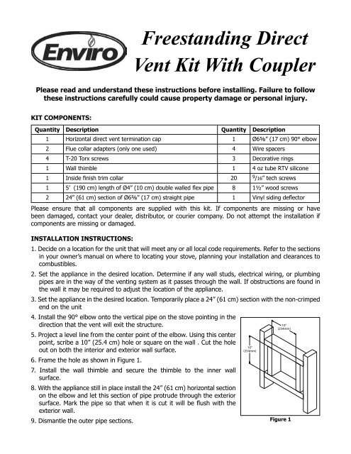
KIT COMPONENTS:<br />
<strong>Freestanding</strong> Direct<br />
Vent <strong>Kit</strong> With Coupler<br />
Please read and understand these instructions before installing. Failure to follow<br />
these instructions carefully could cause property damage or personal injury.<br />
Quantity Description Quantity Description<br />
1 Horizontal direct vent termination cap 1 Ø65⁄8” (17 cm) 90° elbow<br />
2 Flue collar adapters (only one used) 4 Wire spacers<br />
4 T-20 Torx screws 3 Decorative rings<br />
1 Wall thimble 1 4 oz tube RTV silicone<br />
1 Inside finish trim collar 20 9 /16” tech screws<br />
1 5’ (190 cm) length of Ø4” (10 cm) double walled flex pipe 8 11⁄2” wood screws<br />
2 24” (61 cm) section of Ø65⁄8” (17 cm) straight pipe 1 Vinyl siding deflector<br />
Please ensure that all components are supplied with this kit. If components are missing or have<br />
been damaged, contact your dealer, distributor, or courier company. Do not attempt the installation if<br />
components are missing or damaged.<br />
INSTALLATION INSTRUCTIONS:<br />
1. Decide on a location for the unit that will meet any or all local code requirements. Refer to the sections<br />
in your owner’s manual on where to locating your stove, planning your installation and clearances to<br />
combustibles.<br />
2. Set the appliance in the desired location. Determine if any wall studs, electrical wiring, or plumbing<br />
pipes are in the way of the venting system as it passes through the wall. If obstructions are found in<br />
the wall it may be required to adjust the location of the appliance.<br />
3. Set the appliance in the desired location. Temporarily place a 24” (61 cm) section with the non-crimped<br />
end on the unit<br />
4. Install the 90° elbow onto the vertical pipe on the stove pointing in the<br />
direction that the vent will exit the structure.<br />
5. Project a level line from the center point of the elbow. Using this center<br />
point, scribe a 10” (25.4 cm) hole or square on the wall . Cut the hole<br />
out on both the interior and exterior wall surface.<br />
6. Frame the hole as shown in Figure 1.<br />
7. Install the wall thimble and secure the thimble to the inner wall<br />
surface.<br />
8. With the appliance still in place install the 24” (61 cm) horizontal section<br />
on the elbow and let this section of pipe protrude through the exterior<br />
surface. Mark the pipe so that when it is cut it will be flush with the<br />
exterior wall.<br />
9. Dismantle the outer pipe sections.<br />
<br />
<br />
<br />
<br />
Figure 1
10. EG28 or EG40: Remove the 4” (10 cm) flue collar from the unit and remove any loose sealant.<br />
Install the new Ø 4” (10 cm) by 5” (12.5 cm) flue collar provided in this kit.<br />
Westport: Install the 4” (10 cm) adaptor into the exhaust outlet on the unit. Apply a bead of high<br />
temperature silicone.<br />
11. Attach the flexible liner to the vent termination cap by placing a small bead of high temperature<br />
silicone on the vent termination and slide the flex liner onto the vent terminal and secure with three<br />
(3) sheet metal screws evenly spaced.<br />
12. Dress the flex liner through the wall thimble and attach the vent<br />
terminal to the outside of the house using four (4) wood screws<br />
provided. The use of non-hardening mastic should be used around<br />
the vent to ensure a watertight seal.<br />
13. Install two (2) wire spacer around the flex pipe. Slide the horizontal<br />
section of pipe over the flexible liner. Ensure the wire spacers are<br />
positioned at either end of the pipe (refer to Figure 2 and 3).<br />
14. Install the horizontal section of pipe through the wall thimble,<br />
ensure that this portion of pipe slides onto the vent termination<br />
cap.<br />
15. Slide the inside finished collar over the horizontal section of pipe<br />
and secure to wall using the screw provided.<br />
16. Slide the 90° elbow over the flex pipe. Do not slip the outer<br />
sections of pipe together, you will require some movement<br />
in these pipe section in order to secure the flex pipe to the<br />
flue outlet on the appliance.<br />
17. Stretch the flex liner to a length long enough to ensure the flex<br />
liner can be easily connected to the flue outlet of the appliance.<br />
18. Install the remaining wire spacers over the flexible liner and install<br />
the vertical section of pipe. Ensure the wire spacers are positioned<br />
at either end of the pipe (refer to Figure 2 and 3).<br />
19. Place a bead of high temperature silicone on the flue pipe and slide<br />
the flex liner over the collar, secure the flex liner with three (3)<br />
sheet metal screws evenly spaced.<br />
20. Align all straight sections of pipe, slipping all joints<br />
together and installing with three (3) sheet metal<br />
screws evenly spaced.<br />
21. Install the brass decorative rings around each joint<br />
making sure this decorative ring covers the sheet metal<br />
screws that secure each section of pipe together and<br />
secure to vent pipe in the slotted tab on the backside of<br />
the pipe so that the fastener would not be seen.<br />
22. Secure the horizontal section of pipe to the inside<br />
finished collar by installing a screw in the tab on the<br />
inside finished collar. This will prevent the pipe from<br />
being disconnected at the vent terminal.<br />
23. Light the appliance and ensure proper operation.<br />
<br />
<br />
Figure 3<br />
Figure 2
Decorative<br />
brass rings<br />
Exhaust 4"<br />
flex pipe<br />
Part Number Option<br />
Figure 4<br />
Wall thimble<br />
fire stop<br />
Inside finished collar<br />
Combustion air<br />
6 5/8" outer pipe<br />
EC-061 <strong>Freestanding</strong> Direct Vent <strong>Kit</strong> With Coupler<br />
MANUFACTURED BY:<br />
SHERWOOD INDUSTRIES LTD.<br />
6782 OLDFIELD RD. SAANICHTON, BC, CANADA V8M 2A3<br />
www.envirofire.biz<br />
August 11, 2004<br />
C-<strong>10561</strong><br />
Wall framing<br />
Horizontal wall<br />
termination<br />
Flue pipe adaptor<br />
for EG28 and EG40<br />
Flue pipe adaptor<br />
for Westport