C-13872 Instruction E44 Owner's Manual.pdf - Enviro
C-13872 Instruction E44 Owner's Manual.pdf - Enviro
C-13872 Instruction E44 Owner's Manual.pdf - Enviro

Create successful ePaper yourself
Turn your PDF publications into a flip-book with our unique Google optimized e-Paper software.
SHERWOOD INDUSTRIES IS AN ENVIRONMENTALLY RESPONSIBLE COMPANY. THIS MANUAL IS PRINTED ON RECYCLED PAPER.<br />
PLEASE KEEP THESE INSTRUCTIONS FOR FUTURE REFERENCE<br />
OWNER’S MANUAL<br />
INSTALLER:<br />
Leave this manual<br />
with the appliance.<br />
CONSUMER:<br />
Retain this manual for<br />
future reference.<br />
FOR YOUR SAFETY<br />
Do not store or use<br />
gasoline or other<br />
flammable vapours<br />
and liquids in the<br />
vicinity of this or any<br />
other appliance.<br />
WARNING: If the information in this manual<br />
is not followed exactly, a fire or explosion may<br />
result causing property damage, personal injury<br />
or loss of life. Installation and service must be<br />
performed by a qualified installer, service agency<br />
or the gas supplier.<br />
This appliance is only for use with the type of gas indicated on<br />
the rating plate. This appliance is not convertible for use with<br />
other gases, unless a certified kit is used.<br />
4001609<br />
WARRANTY REGISTRATION<br />
enviro.com/warranty<br />
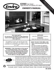
<strong>E44</strong>I Gas Insert -<br />
Log Set & Proflame IPI Valve<br />
WHAT TO DO IF YOU SMELL GAS<br />
• Open windows/extinguish any open<br />
flame.<br />
• Do not try to light any appliance.<br />
• Do not touch any electrical switch<br />
or use any phone in your building.<br />
• Immediately call your gas supplier<br />
from a neighbour’s phone. Follow<br />
the gas supplier’s instructions.<br />
• If you cannot reach your gas<br />
supplier, call the fire department.<br />
Massachusetts installations (Warning): This product must be installed by a licensed plumber or gas fitter<br />
when installed within the Commonwealth of Massachusetts. Other Massachusetts code requirements:<br />
Flexible connector must not be longer than 36in., a shut off valve must be installed; only direct vent<br />
sealed combustion products are approved for bedrooms/bathrooms. A carbon monoxide detector is<br />
required in all rooms containing gas fired direct vent appliances. The fireplace damper must be removed<br />
or welded in the open position prior to installation of a fireplace insert.<br />
50-2628
FOR SAFE INSTALLATION AND OPERATION OF YOUR “ENVIRO” HEATER,<br />
PLEASE CAREFULLY READ THE FOLLOWING INFORMATION:<br />
2<br />
Safety Precautions<br />
• All ENVIRO gas-fired appliances must be installed in<br />
accordance with their instructions. Carefully read all the<br />
instructions in this manual first. Consult the building<br />
authority having jurisdiction to determine the need for a<br />
permit prior to commencing the installation.<br />
• NOTE: Failure to follow these instructions could cause<br />
a malfunction of the fireplace, which could result in death,<br />
serious bodily injury, and/or property damage.<br />
• Failure to follow these instructions may also void your<br />
fire insurance and/or warranty.<br />
GENERAL<br />
• Installation and repair should be done by a qualified<br />
service person. The appliance should be inspected before<br />
the first use and, at least, annually by a qualified service<br />
person. More frequent cleaning may be required due to<br />
excessive lint from carpeting, bedding material, etc. It<br />
is imperative the control compartments, burners and<br />
circulating air passageways of the appliance be kept<br />
clean.<br />
• Due to high temperatures, the appliance should be<br />
located out of high traffic areas and away from furniture<br />
and draperies.<br />
Children and adults should be alerted to the<br />
hazards of high surface temperatures and should<br />
stay away to avoid burn or clothing ignition.<br />
• Young children should be carefully supervised when<br />
in the same room as the appliance. Toddlers, young<br />
children and others may be susceptible to accidental<br />
contact burns. A physical barrier is recommended if there<br />
are at risk individuals in the house. To restrict access to a<br />
fireplace or stove install an adjustable safety gate to keep<br />
toddlers, young children and other at risk individuals<br />
out of the room and away from hot surfaces. Any safety<br />
screen or guard removed for servicing an appliance must<br />
be replaced prior to operating the appliance.<br />
• Clothing or other flammable materials should not be<br />
placed on or near the appliance.<br />
WARNING<br />
HOT GLASS WILL<br />
CAUSE BURNS<br />
DO NOT TOUCH<br />
GLASS UNTIL COOLED.<br />
NEVER ALLOW<br />
CHILDREN TO TOUCH<br />
GLASS.<br />
FOR YOUR SAFETY<br />
• Installation and service must be performed by a qualified<br />
installer, service agency or gas supplier.<br />
• This installation must conform to local codes or, in the<br />
absence of local codes, with the National Fuel Gas Code,<br />
ANSI Z223.1/NFPA 54, or the Natural Gas and Propane<br />
Installation Code, CSA B149.1.<br />
• To prevent injury, do not allow anyone who is unfamiliar<br />
with the stove to operate it.<br />
• To prevent injury, if the pilot or pilot and burners<br />
have gone out on their own, open the glass door and<br />
wait 5 minutes to air out before attempting to relight<br />
the stove.<br />
• Always keep the area around these appliances clear of<br />
combustible material, gasoline and other flammable liquids<br />
and vapours.<br />
• These appliances should not be used as a drying rack for<br />
clothing or for hanging Christmas stockings/decorations.<br />
• Due to the paint curing on the stove, a faint odor and slight<br />
smoking will likely be noticed when the stove is first used.<br />
Open a window until the smoking stops.<br />
Always connect this gas stove to a vent system and vent to<br />
the outside of the building envelope. Never vent to another<br />
room or inside the building. Make sure the specified vent<br />
pipe is used, properly sized and of adequate height to<br />
provide sufficient draft. Inspect the venting system annually<br />
for blockage and signs of deterioration.<br />
WARNING: Failure to position the parts in accordance<br />
with the diagrams in this booklet, or failure to use only<br />
parts specifically approved with this appliance, may result in<br />
property damage or personal injury.<br />
WARNING: Do not operate with the glass front removed,<br />
cracked or broken. Replacement of the glass should be done<br />
by a licensed or qualified service person.<br />
• Never use solid fuels such as wood, paper, cardboard, coal,<br />
or any flammable liquids, etc., in this appliance.<br />
• Do not use this appliance if any part has been under water.<br />
Immediately call a qualified service technician to inspect the<br />
appliance and to replace any part of the control system or<br />
any gas control which has been under water.<br />
• Do not abuse the glass by striking it or slamming the door<br />
shut.<br />
• If the <strong>E44</strong> unit is pulled out of its installation, and the ventair<br />
intake system is disconnected for any reason, ensure that<br />
the vent-air intake pipes are reconnected and re-sealed in<br />
accordance to the instructions noted in InItIal InstallatIon -<br />
VentIng FIreplace Inserts.
Table of Contents<br />
Safety Precautions...........................................................................................................2<br />
Table of Contents.............................................................................................................3<br />
Codes And Approvals.......................................................................................................4<br />
Specifications..................................................................................................................5<br />
Rating Label Location...........................................................................................5<br />
Dimensions..........................................................................................................5<br />
<strong>E44</strong> Options Dimensions.......................................................................................6<br />
Operating <strong>Instruction</strong>s.....................................................................................................7<br />
Lighting and Turning Off <strong>Instruction</strong>s.....................................................................7<br />
Venturi Adjustment...............................................................................................8<br />
Normal Sounds During Operation.........................................................................8<br />
Remote Control Operations...................................................................................9<br />
Wall Mounting the Receiver.................................................................................11<br />
Initializing the System for the First Time..............................................................11<br />
Maintenance And Service................................................................................................14<br />
Cleaning The Glass.............................................................................................14<br />
Cleaning The Firebox..........................................................................................14<br />
Replacing The Glass............................................................................................14<br />
Check Pilot and Burner Flames............................................................................15<br />
Glass Door Removal...........................................................................................15<br />
Cleaning The Painted Surfaces............................................................................15<br />
Removing Valve Cover.........................................................................................16<br />
Removing/Replacing Convection Fan...................................................................17<br />
Fuel Conversion..................................................................................................18<br />
Initial Installation...........................................................................................................20<br />
Clearances to Combustibles.................................................................................20<br />
Minimum Fireplace Size.......................................................................................20<br />
Direct Vent Model...............................................................................................20<br />
Venting Fireplace Inserts.....................................................................................21<br />
Direct Vent Vertical Vent Termination...................................................................23<br />
Installing the Unit...............................................................................................24<br />
Zero Clearance Fireplace Installation...................................................................25<br />
Electrical Requirements.......................................................................................25<br />
Gas Line Connection...........................................................................................27<br />
Adjusting The Pilot Flame....................................................................................29<br />
Continuous Pilot Mode.........................................................................................30<br />
Secondary Installation....................................................................................................30<br />
Optional Base Shelf & Riser.................................................................................30<br />
Optional Trimmable Panel....................................................................................31<br />
Surround Panel Installation..................................................................................32<br />
Firebox Liner and Burner Tube Removal / Installation..............................................33<br />
Log Set and Ember Removal / Installation..............................................................34<br />
Trouble Shooting............................................................................................................37<br />
Parts List.......................................................................................................................40<br />
Options List...................................................................................................................41<br />
Parts Diagram - Components............................................................................................42<br />
Parts Diagram - Options...................................................................................................43<br />
Warranty.......................................................................................................................44<br />
Installation Data Sheet...................................................................................................45<br />
3
DIRECT VENT: This type is identified by the suffix DV. This appliance draws all of its air for combustion from<br />
outside the dwelling, through a specially designed vent pipe system.<br />
This appliance has been tested and approved for installations from 0 feet to 4500 feet (1372 m) above sea level.<br />
In the USA: The appliance may be installed at higher altitudes. Please refer to your American Gas Association<br />
guidelines which state: the sea level rated input of Gas Designed Appliances installed at elevations above 2000<br />
(610 m) feet is to be reduced 4% for each 1000 feet (305 m) above sea level. Refer also to local authorities or<br />
codes which have jurisdiction in your area regarding the de-rate guidelines.<br />
In Canada: When the appliance is installed at elevations above 4500 feet (1372 m), the certified high altitude<br />
rating shall be reduced at the rate of 4% for each additional 1000 feet (305 m).<br />
• This appliance has been tested by Intertek and found to comply with the established<br />
VENTED GAS FIREPLACE HEATER standards in CANADA and the USA as follows:<br />
DIRECT VENTED GAS FIREPLACE INSERT HEATER<br />
TESTED TO: ANSI Z21.88-2009/CSA 2.33-2009 VENTED GAS FIREPLACE HEATERS<br />
CAN/CGA 2.17-M91 (R2009) GAS FIRED APPLIANCES FOR HIGH ALTITUDES<br />
CSA P.4.1-09 TESTING METHOD FOR MEASURING ANNUAL FIREPLACE EFFICIENCY<br />
This ENVIRO <strong>E44</strong> Fireplace Insert:<br />
• Has been certified for use with either natural or propane gases. (See rating label.)<br />
• Is not for use with solid fuels.<br />
• Is approved for bedroom or bed sitting room. (IN CANADA: must be installed with a permanent wall thermostat<br />
for bedroom installations. Consult the authority having local jurisdiction in your area. IN USA: see current ANSI<br />
Z223.1 for installation instructions.)<br />
• Must be installed in accordance with local codes. If none exist, use current installation code CAN/CGA B149 in<br />
Canada or ANSI Z223.1/NFPA 54 in the USA.<br />
• Must be properly connected to an approved venting system and not connected to a chimney flue serving a<br />
separate solid-fuel burning appliance.<br />
• Is not approved for closet or recessed installations.<br />
4<br />
Codes And Approvals<br />
IMPORTANT NOTICE (Regarding first fire up): When the unit is turned on<br />
for the first time, it should be turned onto high without the fan on for the first 4<br />
hours. This will cure the paint, logs, gasket material and other products used in the<br />
manufacturing process. It is advisable to open a window or door, as the unit will start<br />
to smoke and can irritate some people. After the unit has gone through the first burn,<br />
turn the unit off, let the unit get cold then remove the glass door and clean it with a<br />
good gas fireplace glass cleaner, available at your local ENVIRO dealer. See “Door<br />
remoVal” and “cleanIng the glass” sections.
Rating LabeL Location:<br />
Specifications<br />
The rating label is located on the left side of the unit, next to the receiver box.<br />
Dimensions:<br />
2.17<br />
12.08<br />
4.42<br />
18.57<br />
18.60<br />
8.40<br />
34.15<br />
24.17<br />
10.09 10.08<br />
10.56<br />
14.79<br />
23.82 24.77<br />
20.85<br />
24.77<br />
23.82<br />
20.85<br />
22.76<br />
21.06<br />
Figure 1: <strong>E44</strong> Exterior Dimensions.<br />
18.57<br />
18.60<br />
45.00<br />
31.03<br />
29.33<br />
46.33<br />
4.42<br />
2.17<br />
30.13<br />
32.33<br />
5
6<br />
Specifications<br />
Figure 2: <strong>E44</strong> Contemporary Surround with Base Shelf and Riser.<br />
Table 1: <strong>E44</strong> Options Dimensions.<br />
Regular Surround Contemporary Surround Extruded Surround<br />
Height 30 1 /8” (765 mm) 30 1 /8” (765 mm) 30 1 /8” (765 mm)<br />
Width 45” (1143 mm) 45” (1143 mm) 45” (1143 mm)<br />
Trimmable<br />
Surround<br />
32 5⁄16”<br />
45”<br />
46 5⁄16”<br />
30 1⁄8”<br />
Height Width<br />
36” (914mm) 55” (1397mm)<br />
Base Shelf Base Shelf Riser<br />
Height 1 ⅝” (41 mm) 2 ⅛” (54 mm)<br />
Width 46 5 /16” (1176 mm) 44 7 /8” (1140 mm)<br />
Depth Bottom 4 ⅞” (112 mm); Top 3 13 /16” (97 mm) 3 11 /16” (94 mm)
Operating <strong>Instruction</strong>s<br />
For Your Safety, Read Safety Precautions And Lighting <strong>Instruction</strong>s Before Operating<br />
WARNING: IF YOU DO NOT FOLLOW THESE INSTRUCTIONS EXACTLY A FIRE OR EXPLOSION<br />
MAY RESULT, CAUSING PROPERTY DAMAGE, PERSONAL INJURY OR LOSS OF LIFE.<br />
Lighting anD tuRning off instRuctions:<br />
FOR YOUR SAFETY READ BEFORE OPERATING<br />
WARNING:IF YOU DO NOT FOLLOW THESE INSTRUCTIONS EXACTLY, A FIRE OR EXPLOSION<br />
MAY RESULT CAUSING PROPERTY DAMAGE, PERSONAL INJURY OR LOSS OF LIFE.<br />
A. This appliance is equipped with an ignition device<br />
which automatically lights the pilot. Do not try to<br />
light the pilot by hand.<br />
B. BEFORE OPERATING smell all around the<br />
appliance area for gas. Be sure to smell next to the<br />
floor because some gas is heavier than air and will<br />
settle on the floor.<br />
WHAT TO DO IF YOU SMELL GAS:<br />
Do not try to light any appliance.<br />
Do not touch any electrical switch; do not use any<br />
phone in your building.<br />
Immediately call your gas supplier from a<br />
neighbor’s phone. Follow the gas supplier’s<br />
instructions.<br />
If you cannot reach your gas supplier, call the<br />
fire department.<br />
OPERATING INSTRUCTIONS<br />
1. STOP! Read the safety information above on this label.<br />
2. Read the owner's manual including the section on<br />
"Remote Control" operation.<br />
3. Set the thermostat to the lowest setting.<br />
4. Turn off all electric power to the appliance.<br />
5. Do not attempt to light the pilot by hand.<br />
6. Wait five (5) minutes to clear out any gas. Then smell for<br />
gas, including near the floor. If you smell gas, STOP!<br />
Follow "B" in the safety information above on this label.<br />
If you don't smell gas, go to the next step.<br />
7. Turn on all electric power to the appliance.<br />
8. Using the remote control, set<br />
thermostat to desired setting, or<br />
press the ON/OFF key on the<br />
remote. "ON" will be indicated on the<br />
display of the remote and an audible<br />
"beep" will be heard at the unit to<br />
indicate the command has been<br />
received.<br />
TO TURN OFF GAS TO APPLIANCE<br />
Figure 3: Lighting instruction label.<br />
C. Use only your hand to push in or<br />
turn the gas control knob. Never<br />
use tools. If the knob will not push<br />
in or turn by hand, don’t try to<br />
repair it, call a qualified service<br />
technician. Force or attempted<br />
repair may result in a fire or<br />
explosion.<br />
D. Do not use this appliance if any<br />
part has been under water.<br />
Immediately call a qualified service<br />
technician to inspect the appliance<br />
and to replace any part of the<br />
control system and any gas control<br />
which has been under water.<br />
9. This appliance is equipped with a<br />
completely automatic ignition and<br />
lighting control. The control will<br />
attempt to light the pilot several<br />
times if necessary. If it is<br />
unsuccessful, it will discontinue<br />
operations. If the appliance will<br />
not operate, follow the<br />
instructions "To Turn Off Gas To<br />
Appliance" and call your service<br />
technician or gas supplier.<br />
Blue LCD Display<br />
THERMOSTAT Key<br />
ON/OFF Key<br />
UP/DOWN Arrow Key<br />
MODE Key<br />
1. Set thermostat to lowest setting, or press the ON/OFF Key. "OFF" will be indicated on the display<br />
and an audible "Beep" will be heard at the unit to indicate the command has been received.<br />
2. Turn off all electric power to the appliance if service is to be performed.<br />
C-12455<br />
7
8<br />
VentuRi aDjustment:<br />
Operating <strong>Instruction</strong>s<br />
The venturi adjustment lever is located on the right side of the unit, behind the surround panel (see<br />
Figure 4). To avoid touching hot surfaces under the unit, use the Door Tool to adjust the venturi.<br />
The venturi allows the amount of air coming into the fireplace to be adjusted in order to accommodate<br />
different climates and venting arrangements. Start the pilot and then the burner. Make sure the pilot<br />
flame is burning normally and none of the burner ports are plugged. Let the fireplace burn for roughly<br />
fifteen (15) minutes and then examine the flames. The<br />
ideal flame will be blue at the base and light orange<br />
above. The flames should be of medium height. If the<br />
flames look like this, no venturi adjustment is needed. If<br />
the flames are fairly short and mostly blue, the fireplace<br />
is getting too much air. Therefore, the air shutter should<br />
be closed (push in) slightly until the correct flames are<br />
achieved. Flames that are very orange, with tall dark<br />
stringy tips are not getting enough air. Open (pull out)<br />
the venturi until the flames clean up. If the venturi is<br />
opened, then closed all the way, and the correct flames<br />
Figure 4: Adjusting the venturi air setting. cannot be attained, turn off the gas and contact the<br />
dealer.<br />
Warning: Incorrect venturi adjustment may lead to improper combustion, which is a safety hazard.<br />
Contact the dealer if there is any concern about the venturi adjustment.<br />
noRmaL sounDs DuRing opeRation:<br />
Component Sound & Reason<br />
Fire Box Creaking when heating up or cooling down.<br />
Burner Light pop or poof when turned off; this is more common with LP units.<br />
Temperature Sensor Clinking when it senses to turn the blower on or off.<br />
Pilot Flame Quiet whisper while the pilot flame in on.<br />
Blower / Fan Air movement that increases and decreases with the speed of the blower.<br />
Gas Control Valve Dull click when turning on or off, this is the valve opening and closing.<br />
Receiver Beeps when remote control buttons are pressed.<br />
Table 2: Normal Sound
Remote contRoL opeRations:<br />
Operating <strong>Instruction</strong>s<br />
The Proflame GTMF is a modular remote control system that directs the functions of the <strong>E44</strong>. The Proflame<br />
GTMF is configured to control the on/off main burner operation, its flame levels and provides on/off and<br />
Smart thermostatic control of the appliance. The system controls a remotely actuated 120V/60Hz power<br />
outlet, fan speed through six (6) levels and has a constantly powered 120V/60Hz power outlet.<br />
ATTENTION!<br />
- TURN “OFF” THE MAIN GAS SUPPLY OF THE APPLIANCE DURING INSTALLATION OR<br />
MAINTENANCE OF THE RECEIVER.<br />
- PLACE THE RECEIVER’S 3 POSITION SLIDER SWITCH IN THE “OFF” POSITION DURING<br />
INSTALLATION OR MAINTENANCE.<br />
- TURN “OFF” MAIN GAS SUPPLY TO THE APPLIANCE PRIOR TO REMOVING OR REINSERTING<br />
THE BATTERIES IN THE RECEIVER.<br />
- DURING APPLIANCE INSTALLATION/MAINTENANCE OR IN CASE OF REMOTE CONTROL<br />
MALFUNCTION TURN OFF THE FAN CONTROL MODULE USING THE “ON/OFF” MAIN POWER<br />
SWITCH ON THE FRONT PANEL OF THE FCM.<br />
technicaL Data<br />
Transmitter (Remote Control):<br />
Supply voltage: 4.5 V (three 1.5 V AAA batteries)<br />
Radio frequency: 315 MHz<br />
Receiver:<br />
Supply voltage: 6.0 V (four 1.5 V AA batteries)<br />
Radio frequency: 315 MHz<br />
Fan Control Module:<br />
Supply voltage / frequency: 120 V / 60 Hz<br />
Aux switched output: 120 V / 60 Hz / 2 A<br />
Fan speed output: 120 V / 60 Hz / 1 A<br />
Digital Fireplace Controller:<br />
Supply voltage: DC IN - 7 Vdc - 200mA (Class 2 power supply)<br />
BB IN - 6 Vdc - 200mA (four 1.5 V AA batteries)<br />
Spark voltage / frequency: >15kV / 1Hz<br />
system DescRiption:<br />
The Proflame Remote Control System consists of three (3) elements:<br />
1. Proflame Transmitter.<br />
2. Proflame Receiver and a wiring harness to connect the Receiver to the gas valve, stepper motor and<br />
Fan Control Module.<br />
3. Proflame Fan Control Module (FCM)<br />
4. Digital Fireplace Controller (DFC)<br />
9
10<br />
Operating <strong>Instruction</strong>s<br />
TRANSMITTER (Remote Control with LCD<br />
Display)<br />
The Proflame Transmitter uses a streamline<br />
design with a simple button layout and<br />
informative LCD display (Figure 5). The<br />
Transmitter is powered by three (3) AAA type<br />
batteries. A Mode Key is provided to Index<br />
between the features and a Thermostat<br />
Key is used to turn on/off or index through<br />
Thermostat functions (Figure 5 & 6).<br />
Figure 5: Proflame Transmitter.<br />
Split Flow<br />
Figure 6: Proflame Transmitter LCD Screen.<br />
RECEIVER<br />
The Proflame Receiver (Figure 7) connects directly to<br />
the gas valve, stepper motor, DFC, and Fan Control<br />
Module with a wiring harness. The Receiver is<br />
powered by four (4) AA type batteries. The Receiver<br />
accepts commands via radio frequency from the<br />
Transmitter to operate the appliance in accordance<br />
with the particular Proflame system configuration.<br />
The Receiver three (3) position slider switch can be<br />
set to one of three positions: ON (<strong>Manual</strong> Override),<br />
Remote (Remote control), or Off.<br />
Figure 7: Proflame Receiver.<br />
Figure 8: Proflame Fan Control Module.<br />
FAN CONTROL MODULE<br />
Fan Control Module (FCM) offers the added<br />
ability to control the fan speed through six (6)<br />
speeds, a remotely actuated 120V outlet and<br />
a constantly powered 120V outlet. The FCM<br />
provides DC power to the Receiver allowing the<br />
batteries to be used only when line power is<br />
interrupted or lost (see Figure 8).
Slider<br />
Switch<br />
Wall Plate<br />
opeRating pRoceDuRe:<br />
Operating <strong>Instruction</strong>s<br />
Remote mounting the ReceiVeR (optionaL):<br />
The receiver can be removed from the unit and placed inside a standard Junction type wall box or another<br />
convenient location. This installation can take place up to 6’ft (1.8 m) from the appliance control valve.<br />
1. Connect the wiring harness to the back of the<br />
Receiver.<br />
2. Install the Receiver in the Junction box using the<br />
existing J box screws (Figure 9).<br />
3. Insert the four (4) AA type batteries in the battery<br />
compartment with the correct polarity.<br />
4. Place the slider into the cover plate.<br />
Receiver<br />
J-Box<br />
Figure 9: Wall Mounting the Receiver.<br />
5. Put the Receiver switch in the “OFF” position.<br />
6. Make sure the Receiver and cover plate words “ON”<br />
and “UP” are on the same side.<br />
7. Align the slider with the switch on the Receiver and<br />
couple the switch into the slider.<br />
8. Align the screw holes.<br />
9. Using the two (2) screws provided secure the cover<br />
plate to the Receiver.<br />
Initializing The System For The First Time<br />
Install the four (4) AA batteries into the receiver battery bay. Note the polarity of the battery and insert into<br />
the battery bay as indicated on the Battery cover (+/-). Place the 3-position slider switch in the “Remote”<br />
position (see Figure 7). Using the end of a paper clip, or other similar object, insert the end of the paper clip<br />
into the hole marked “PRG” on the Receiver front cover (see Figure 7).<br />
The Receiver will “beep” three (3) times to indicate that it is ready to synchronize with a Transmitter. Install<br />
the three (3) AAA type batteries in the Transmitter battery bay, located on the base of the Transmitter. With<br />
the batteries already installed in the Transmitter, push the ‘ON’ button. The Receiver will “beep” four (4)<br />
times to indicate the Transmitter’s command is<br />
accepted and sets to the particular code of that<br />
Transmitter. The system is now initialized.<br />
Temperature Indication Display<br />
With the system in the “OFF” position, press the<br />
Thermostat Key and the Mode Key at the same<br />
time. Look at the LCD screen on the transmitter<br />
to verify that a °C or °F is visible to the right of<br />
the Room Temperature display (see Figure 10).<br />
Figure 10: Remote Control Display in Farenheit and Celcius.<br />
Turn on the Appliance<br />
Press the ON/OFF Key on the Transmitter. The Transmitter display will show all active Icons on the screen. A<br />
single “beep” from the Receiver will confirm reception of the command and will commence to first ignite the<br />
pilot light, followed by the main burner. This should take about 10 seconds to complete.<br />
11
12<br />
Operating <strong>Instruction</strong>s<br />
Turn off the Appliance<br />
Press the ON/OFF Key on the Transmitter. The Transmitter LCD display<br />
will only show the room temperature and Icon (see Figure 11). A single<br />
“beep” from the Receiver confirms reception of the command and both<br />
the pilot light (if the unit is not set to continuous pilot) and main burner<br />
will turn off.<br />
Thermostat ON<br />
Room Temperature<br />
Room Thermostat (Transmitter Operation)<br />
The Remote Control can operate as a room thermostat. The thermostat<br />
can be set to a desired temperature to control the comfort level in a<br />
Set Temperature<br />
room. To activate this function, press the Thermostat Key (see Figure<br />
5). The LCD display on the Transmitter will change to show that the<br />
Figure 11: Remote Control Displays<br />
room thermostat is “ON” and the set temperature is now displayed (see<br />
Set Temperature.<br />
Figure 11). To adjust the set temperature, press the Up or Down Arrow<br />
Keys until the desired set temperature is displayed on the LCD screen of the Transmitter.<br />
Smart Thermostat (Transmitter Operation)<br />
The Smart Thermostat function adjusts the flame height in accordance to the difference between the set<br />
point temperature and the actual room temperatures. As the room temperature gets closer to the set point<br />
the Smart Function will modulate the flame down. To activate this function, press the Thermostat Key (Figure<br />
6) until the word “SMART” appears to the right of the temperature bulb graphic (Figure 12). To adjust the<br />
set temperature, press the Up or Down Arrow Keys until the desired set temperature is displayed on the LCD<br />
screen of the Transmitter.<br />
Figure 12: Remote Control’s Smart Flame Function.<br />
Remote Flame Control<br />
The Proflame GTMF has six (6) flame levels. With<br />
the system on, and the flame level at the maximum<br />
in the appliance, pressing the Down Arrow Key once<br />
will reduce the flame height by one step until the<br />
flame is turned off. The Up Arrow Key will increase<br />
the flame height each time it is pressed. If the Up<br />
Arrow Key is pressed while the system is on but<br />
the flame is off, the flame will come on in the high<br />
position (refer to Figure 13). A single “beep” will<br />
confirm reception of the command.<br />
Flame Off Flame Level 1<br />
Flame Level 5 Maximum Flame Level<br />
Figure 13: Remote Control’s Flame Levels.
Operating <strong>Instruction</strong>s<br />
Key lock<br />
This function will lock the keys to avoid<br />
unsupervised operation. To activate this function,<br />
press the MODE and UP keys at the same time<br />
and the a lock will appear (see Figure 15). To<br />
de-activate this function, press the MODE and<br />
UP Keys at the same time.<br />
Low Battery Power Detection<br />
Transmitter: The life span of the remote control<br />
batteries depends on various factors: quality of<br />
the batteries used, the number of ignitions of<br />
the appliance, the number of changes to the<br />
room thermostat set point, etc. When the<br />
Transmitter batteries are low, a Battery Icon will<br />
appear on the LCD display of the Transmitter<br />
(see Figure 16) before all battery power is lost.<br />
When the batteries are replaced this Icon will<br />
disappear.<br />
Receiver: The life span of the Receiver batteries<br />
depends on various factors: quality of the<br />
batteries used, the number of ignitions of the<br />
appliance, the number of changes to the room<br />
Figure 14: Remote Control with Aux for Accent Lights.<br />
Figure 15: Remote Control<br />
Locked.<br />
Figure 16: Low Battery<br />
Indicator.<br />
thermostat set point, etc. When the Receiver batteries are low, No “beep” will be emitted from the Receiver<br />
when it receives an On/Off command from the Transmitter. This is an alert for a low battery condition for the<br />
Receiver. When the batteries are replaced the “beep” will be emitted from the Receiver when the ON/OFF Key<br />
is pressed (See Initializing The System For The First Time).<br />
<strong>Manual</strong> Bypass Of The Remote System<br />
If the batteries of the Receiver or Transmitter are low or depleted, the appliance can be turned on manually by<br />
sliding the three position slider switch on the Receiver to the ON position. This will bypass the remote control<br />
feature of the system and the appliance main burner will come on.<br />
WARNING: Fire Hazard. Can cause severe injury or death The Receiver causes ignition of the<br />
appliance. The appliance can turn on suddenly. Keep away from the appliance burner when<br />
operating the remote system or activating manual by pass of the remote system.<br />
WARNING: Shock Hazard. Can cause severe injury or death. This device is powered by line<br />
voltage. Do not try to repair this device. In no way is the enclosure to be tampered with or<br />
opened. Disconnect from line voltage before performing any maintenance.<br />
WARNING: Devices rated more than 5A shall not be connected to the OUT receptacle. Devices<br />
rated more than 1A shall not be connected to the FAN receptacle. Devices rated more than 2A<br />
shall not be connected to the AUX receptacle.<br />
CAUTION: Property Damage Hazard. Excessive heat can cause property damage. The appliance<br />
can stay lit for many hours. Turn off the appliance if it is not going to be attended for any length<br />
of time. Always place the Transmitter where children cannot reach it.<br />
13
14<br />
Maintenance And Service<br />
Warning: Failure to position the parts in accordance with this manual, or failure to use only parts<br />
specifically approved with this appliance, may result in property damage or personal injury.<br />
The appliance area should be kept clear and free from combustible materials, gasoline, and other<br />
flammable vapors and liquids.<br />
At least once a year, run through the following procedures to ensure the system is clean and working<br />
properly. Check the burner to see if all the ports are clear and clean. Check the pilot to make sure it is not<br />
blocked by anything. The pilot flame should be blue with little or no yellow on the tips.<br />
The venting system must be periodically examined; it is recommended the examination is done by a<br />
qualified person.<br />
Always ensure that the flow of combustion and ventilation air is not obstructed is any way.<br />
cLeaning the gLass:<br />
When the fireplace is cool, remove the glass door. See maIntenance anD serVIce - glass Door remoVal.<br />
Check the gasket material on the back of the glass, making sure that it is attached and intact.<br />
During a cold start up, condensation will form on the glass. This is a normal condition with all fireplaces.<br />
However, this condensation can allow dust and lint to cling to the glass surface. Initial paint curing of the<br />
appliance can leave a slight film on the glass. The glass will need cleaning after the fireplace has cooled<br />
off from the first burn and about two weeks after first burn. Use a mild glass cleaner and a soft<br />
cloth. Abrasive cleaners will damage the glass and painted surfaces. Depending on the amount<br />
of use, the glass should require cleaning no more than two or three times a season. Do not clean the<br />
glass when it is hot.<br />
cLeaning the fiRebox:<br />
Remove the logs carefully, as they are very fragile. Gently remove all the embers and rock wool and<br />
place on a paper towel. Vacuum the bottom of the firebox thoroughly. Carefully clean any dust off the<br />
logs and remove any lint from the burner and pilot. At this time, inspect the burner tube for cracking or<br />
severe warping. If a problem is suspected, contact the dealer. Check the logs for deterioration or large<br />
amounts of soot; a small amount on the logs is normal. Replace the logs and embers as in the seconDary<br />
InstallatIon - log set anD ember InstallatIon section. If new/more embers and rock wool are required,<br />
contact your nearest ENVIRO dealer.<br />
RepLacing the gLass:<br />
The glass in the fireplace is a high temperature ceramic. If the glass is damaged in any way, a factory<br />
replacement is required (see parts lIst). Wear gloves when handling damaged glass door assembly<br />
to prevent personal injury. Do not operate with the glass front removed, cracked or broken. Removal<br />
and replacement of the glass from the door must be done by a licensed or qualified service person.<br />
The glass must be purchased from an ENVIRO dealer. No substitute materials are allowed.<br />
Remove the door (see page 15). The replacement glass will come with a new gasket installed. Remove<br />
any silicone remnants from the door. Apply high temperature silicone to the two vertical faces of the<br />
door and install the new piece of glass with gasket (be sure to maintain edge clearances). Apply even<br />
pressure to the glass to allow the silicone to adhere to the gasket material.
Maintenance And Service<br />
check piLot anD buRneR fLames:<br />
Periodically do a visual check of the pilot flames. One flame should encompass<br />
the thermocouple and the other should burn over the burner ports (see<br />
Figure 17). Also check that the burner is operating correctly, refer to Venturi<br />
Adjustment section.<br />
gLass DooR RemoVaL:<br />
Figure 18: Door Release.<br />
cLeaning the painteD suRfaces:<br />
Figure 19: Door Removal.<br />
Painted surfaces should be periodically wiped with a damp cloth when the unit is cool.<br />
Figure 17: Pilot Flame<br />
Remove the glass door by placing the hooked end of the door release tool in the hole on the<br />
door latch mechanism (see Figure 18) and pulling the latch out then up. When the two (2)<br />
latches have been released, tilt the bottom of the door forward and then lift up to unhook<br />
the top door tabs (see Figure 19).<br />
Re-assemble in the reverse order.<br />
Warning: Do not touch or attempt to remove the glass if the fireplace is not completely cool.<br />
Never operate the fireplace with the glass removed.<br />
CAUTION GLASS MAY SEPARATE FROM DOOR.<br />
15
16<br />
RemoVing VaLVe coVeR:<br />
Maintenance And Service<br />
The valve cover can be removed to access the gas valve.<br />
1. Use a T-20 screwdriver to remove the four screws that hold down the valve cover shown in Fig. 20.<br />
Figure 20: Valve Cover.<br />
VALVE<br />
COVER
Maintenance And Service<br />
RemoVing/RepLacing conVection fan:<br />
The fan assembly can be removed to access the convection blower.<br />
1. Use a T-20 screwdriver to remove the screws that hold the Fan Mounting Plate in place See Figure 21.<br />
2. Tilt the assembly back and pull it away from the unit.<br />
3. The Fan is removed from the Mounting Plate by removing the six (6) screws that hold it in place<br />
using a T-20 screwdriver.<br />
4. The fan can then be disconnected from the wiring harness (See Figure 22 for fan wiring).<br />
5. To replace fan, follow steps 1-4 in reverse order.<br />
Black<br />
Convection Blower<br />
Temperature Sensor<br />
White<br />
Figure 22: Fan Wiring.<br />
Black<br />
Green<br />
Ground<br />
FCM<br />
Figure 21: Fan Mount Removal.<br />
17
18<br />
Fuel Conversion<br />
TO BE INSTALLED BY A QUALIFIED SERVICE AGENCY ONLY<br />
Please read and understand these instructions before installing.<br />
WARNING: This conversion kit shall be installed by a qualified service agency in accordance<br />
with the manufacturer’s instructions and all applicable codes and requirements of the<br />
authority having jurisdiction. If the information in these instructions is not followed<br />
exactly, a fire, explosion or production of carbon monoxide may result causing property<br />
damage, personal injury or loss of life. The qualified service agency is responsible for<br />
the proper installation of this kit. The installation is not proper or complete until the<br />
operation of the converted appliance is checked as specified in the manufacturer’s<br />
instructions supplied with the kit.<br />
Kit Parts List:<br />
1 - Orifice (NG - #31 DMS or LP #50 DMS) 1 - Servo regulator with diaphragm<br />
1 - Conversion label 1 - Installation instruction sheet<br />
Carefully inspect the orifice supplied with this conversion kit. If it has been damaged or is missing,<br />
contact your dealer, distributor or courier company to have it replaced before starting this installation.<br />
NOTE: The unit is shipped from the factory adjusted for use with NATURAL gas.<br />
1. Ensure all the components of the conversion kit are accounted for.<br />
2. If the unit has already been connected to a gas supply, shut off the gas supply to the unit.<br />
CAUTION: The gas supply must be shut off prior to disconnecting the electrical power and before<br />
proceeding with the conversion.<br />
3. If the unit has been run, shut off and allow cooling to room temperature.<br />
4. Remove the glass as shown in the Maintenance and Service - Glass Door Removal.<br />
5. Carefully remove the log set and ember material if they are installed.<br />
6. Remove the burner as shown in the Maintenance and Service - Burner Removal.<br />
7. Convert the pilot injector:<br />
a) Using a 7 /16” wrench, turn the pilot head a ¼ turn counter-clockwise.<br />
b) Push the slider, with your finger or flat head screwdriver.<br />
-Natural gas is marked NAT.<br />
-Propane gas is marked LP with an indicating hole between L and P. It is also marked red.<br />
c) Turn the pilot head a ¼ turn clockwise; back to its original position.<br />
8. Convert the burner orifice(s):<br />
a) Remove the main burner orifice with a 1/2” deep socket.<br />
b) Put a bead of pipe-thread sealant on the orifice threads before installing.<br />
c) Install the new orifice from the kit into the orifice mount. DO NOT OVER-TIGHTEN.<br />
9. Convert the SIT gas valve:<br />
a) Remove Valve Cover.<br />
b) Use a T-20 driver to remove the two screws that hold the servo regulator to the gas valve.<br />
c) Remove the rubber regulator diaphragm that is situated between the servo regulator and the<br />
valve body and replace it with the one provided in the kit.<br />
d) Install the LP servo regulator, with the new longer T-20 screws included in the kit.<br />
e) Reinstall the Valve Cover plate.
Fuel Conversion<br />
10. Reinstall the burner, brick panels, log set, embers, and glass door. Also refer to seconDary InstallatIon<br />
- InstallIng log set anD embers in your Owner’s <strong>Manual</strong>. When re-installing the burner, ensure that<br />
the burner to pilot hood relationship is similar to what is shown in Figure 23.<br />
11. Reconnect the electrical power to the unit.<br />
12. Refer to the Operating <strong>Instruction</strong>s to light the unit and verify proper burner ignition and operation<br />
and proper flame appearance.<br />
13. MAKE SURE that the conversion label is installed on or close to the rating label to signify that the<br />
unit has been converted to a different fuel type.<br />
Figure 23. Ignitor assembly<br />
beside the burner.<br />
19
20<br />
Initial Installation<br />
WARNING: Operation of this heater when not connected to a properly installed and maintained<br />
venting system can result in carbon monoxide (CO) poisoning and possible death.<br />
cLeaRances to combustibLes:<br />
Maintain sufficient clearances for operation, service and<br />
maintenance.<br />
• A minimum distance of 23 1 /2” (597 mm) is required<br />
from the centerline of the unit to the sidewalls.<br />
• Minimum clearance for any combustible facing is 40”<br />
(1016 mm) from the bottom of the unit.<br />
• A 8” (203 mm) wide mantel can be mounted at a<br />
minimum height of 40” (1016 mm) from the bottom of<br />
unit.<br />
• If installed with a minimum of 1 /2” (13 mm) raised<br />
hearth, there must be a minimum of 16” (406 mm) of<br />
non-combustible material in front of the unit.<br />
• If installed where the hearth is flush with the<br />
combustible flooring, there must be a minimum of 18”<br />
(457 mm) of non-combustible material in front of the<br />
unit.<br />
• Minimum ceiling clearance is 60” (1524 mm) from<br />
bottom of unit.<br />
minimum fiRepLace size:<br />
8" (203mm) Mantel<br />
Combustible<br />
Facing<br />
40"<br />
(1016 mm)<br />
minimum<br />
from bottom<br />
of unit<br />
16"<br />
(406 mm)<br />
minimum<br />
from wall<br />
If hearth is raised<br />
a minimum of 1/2”<br />
40"<br />
(1016 mm)<br />
minimum<br />
from bottom<br />
of unit<br />
18"<br />
(457 mm)<br />
minimum<br />
from wall<br />
If hearth is<br />
flush with flooring<br />
Figure 24: Mantle width and height.<br />
Table 3: Minimum dimensions of fireplace for <strong>E44</strong> to be installed into.<br />
Width At Front Width At Back Height Depth<br />
Fireplace Dimensions 34” (864 mm) 24” (610 mm) 24” (610 mm) 18 1 /2” (470 mm)<br />
NOTE: Space must be provided for gas line on right side of unit for servicing purposes.<br />
DiRect Vent:<br />
non-combustible<br />
hearth<br />
WARNING: This appliance has been designed to draw room air for proper heat circulation<br />
from the sides of the unit, and out the top front. Blocking or modifying these openings in<br />
any way can create hazardous situations.<br />
The vent length for the <strong>E44</strong> must be between 15ft (4.5 m) and 40ft (12 m).<br />
This model is vented with a 3” intake and a 3” exhaust aluminum or stainless steel approved flex vent<br />
leading into a vertical termination cap. The flue collars of this model will fit inside of a standard 3” vent<br />
and must be fastened directly to the vent with three screws. The exhaust vent and air intake are both<br />
located on the top of the unit.<br />
Check periodically that the vents are unrestricted. Also ensure that all direct vent pipes have been<br />
properly sealed and installed after routine inspection or cleaning. The air intake and exhaust pipes must<br />
be installed in the correct locations on the top of the <strong>E44</strong>.
Venting fiRepLace inseRts:<br />
Initial Installation<br />
QUALIFIED INSTALLERS ONLY<br />
The ENVIRO <strong>E44</strong> may be installed and vented into any solid fuel fireplace that has been installed in<br />
accordance with the National, Provincial/State and local building codes and has been constructed of noncombustible<br />
materials. Before starting, refer to InItIal InstallatIon - preparIng your e44 For InstallatIon.<br />
Please reference the information in Table 4 and Figures 25, and 27.<br />
An approved chimney liner and rain cap must be used. A throat connector or flashing must be installed to<br />
ensure a tight seal, top performance, safety and efficiency. Carefully follow the manufacturer’s instructions<br />
that accompany the chimney liner kit. Use double walled aluminum flex vent (3” flex conversion piece and<br />
4”x 6 5/8” cap) from any of the following approved products; Simpson Dura-Vent (Direct Vent GS) or (ICC<br />
Excel Direct). If necessary, remove the vent collar plate from the top of the insert and connect it securely<br />
to the liner with sheet metal screws.<br />
Check for any tears in the liner at this point. IMPORTANT: The screws that hold the vent collar plate in its<br />
approved position must be installed.<br />
NOTE: If the <strong>E44</strong> unit is pulled out of its installation, and the vent-air intake system is disconnected<br />
for any reason, ensure that the vent-air intake pipes are re-sealed with high-temperature sealant and<br />
reconnected with three (3) sheet metal screws evenly spaced.<br />
Table 4: Vent termination clearances<br />
Minimum Clearance Description<br />
3 ft (0.9 m)<br />
Clearance above the highest point where it passes through a roof surface, refer to<br />
Figure 25.<br />
24 in (0.6 m)<br />
Clearance above a roof ridge, any other portion of a building, or any other obstruction<br />
within a horizontal distance of 10 feet (3 m), refer to Figure 25.<br />
5 ft (1.5 m)<br />
Clearance for a vent or chimney above either the highest connected appliance<br />
drafthood outlet, or flue collar.<br />
6 ft (1.83 m) Clearance to mechanical air supply inlet.<br />
3ft (0.9m) Clearance to each side of center line extended above meter/regulator assembly.<br />
6 ft (1.83 m) Radial clearance around service regulator vent outlet.<br />
12 in (30 cm) Clearance above grade, verandah, porch, deck, or balcony.<br />
Clearance to a building opening or combustion air inlet of another appliance, ex-<br />
3 ft (0.9 m) cept with the approval of the authority having jurisdiction for the following reduced<br />
clearances.<br />
9 in (0.23 m) Exception for inputs up to and including 50,000 Btu/h (15kW)<br />
12 in (0.3 m)<br />
Exception for inputs exceeding 50,000 Btu/h (15kW) but not exceeding 100,000<br />
Btu/h (30kW)<br />
3ft (0.9m)<br />
Minimum<br />
2ft (0.6m)<br />
Minimum<br />
Within<br />
10ft (3m)<br />
Figure 25: Roof Clearances.<br />
Roof ridge or<br />
any other portion<br />
of a building<br />
21
22<br />
Initial Installation<br />
QUALIFIED INSTALLERS ONLY<br />
3" (76mm) Exhaust<br />
3" (76mm) Intake<br />
Figure 26: Generic Vent Cap Underside.<br />
The height for the vent must be between 15 ft (4.5 m) and 40 ft (12 m).<br />
Install a sealed vent cap to prevent leakage of room air up through<br />
chimney.<br />
The intake and the exhaust are 3" (76mm).<br />
Measure the height of the chimney beforehand and purchase the<br />
appropriate venting. Never attempt to over-stretch a flexible liner to<br />
accommodate the height of the chimney. Every joint in the venting must<br />
be secured with three (3) #8 x 3/8” HWH sheet metal screws and an<br />
appropriate sealant (either silicone or stove cement).<br />
The flue damper can be fully blocked open or removed for installation of<br />
the <strong>E44</strong>; the smoke shelves, shields and baffles may be removed if<br />
attached by mechanical fasteners.<br />
The fireplace and fireplace chimney must be clean, in good working order<br />
and constructed of non-combustible materials.<br />
Make sure that all chimney cleanouts are tight fitting and will not permit<br />
air to leak into the chimney.<br />
Refractory, glass doors, screen rails, screen mesh and log grates can be<br />
removed from the fireplace before installing the <strong>E44</strong>.<br />
Figure 27: Installation of <strong>E44</strong> DV .
DiRect Vent VeRticaL Vent teRmination:<br />
instaLLation instRuctions:<br />
Initial Installation<br />
QUALIFIED INSTALLERS ONLY<br />
1. Plan your installation and clearances to combustibles. The <strong>E44</strong> may be installed and vented into<br />
any solid fuel fireplace that has been installed in accordance with the National, Provincial/State and<br />
local building codes and has been constructed of non-combustible materials. Also refer to the InItIal<br />
InstallatIon - preparIng your e44 For InstallatIon and clearances to combustIbles sections. Refer to<br />
Figure 24 throughout installation.<br />
2. Stretch the Ø3” (76mm) flex vent liners to the length needed to ensure they can be easily connected<br />
to the vent terminals.<br />
3. Install the flex pipe assembly up through the chimney, ensure that the pipe slides through far enough<br />
to connect onto the vent cap.<br />
4. Most vent caps can be installed onto chimneys with flue openings up to 16” (406mm) x 16” (406mm)<br />
and the actual flashing is 18”x18” (refer to Figure 28). If the chimney is smaller the cap should be<br />
trimmed down and folded over.<br />
5. Apply a bead of stove cement sealant to the top section of the Ø3” (76mm) exhaust vent collar plate.<br />
Slide the Ø3” (76mm) flex vent over the flue collar and secure with three (3) sheet metal screws<br />
evenly spaced.<br />
6. Place a bead of high temperature silicone on the intake collar of the fireplace, slide the Ø3” (76mm)<br />
flex intake liner over the collar, secure the flex liner with three (3) sheet metal screws evenly spaced.<br />
7. At the top of the chimney, apply a bead of stove cement sealant to the Ø3” (76mm) pipe of the<br />
exhaust vent terminal (refer to Figure 26). Slide the flex liner onto the vent terminal and secure with<br />
three (3) sheet metal screws evenly spaced.<br />
8. Place a bead of high temperature silicone on the intake collar of the vent terminal (refer to Figure 26).<br />
Slide the Ø3” (76mm) flex intake liner over the collar, secure the flex liner with three (3) sheet metal<br />
screws evenly spaced.<br />
9. Make a tight connection between the gas fireplace insert flue collar and the fireplace chimney at the<br />
top of the chimney. Secure the vent terminal to the chimney using adequate sealant, and according<br />
to local building codes.<br />
APPROVED TERMINATIONS:<br />
-Simpson Dura-Vent<br />
46DVA-VCH cap with 46DVA-GK<br />
termination adapter<br />
or 46DVA-CL33 termination kit<br />
-ICC TM-4SVT cap with TM-CTA<br />
termination adapter<br />
Trim flashing<br />
as required.<br />
18"<br />
(457mm)<br />
18"<br />
(457mm)<br />
Figure 28: Generic Vent Cap Dimensions.<br />
23
24<br />
instaLLing the unit:<br />
Initial Installation<br />
QUALIFIED INSTALLERS ONLY<br />
• Remove the packaging from the appliance and surround panels; check to make sure there is no<br />
damage. Carefully check the glass door. Do not use the unit if it is damaged. In the event damage is<br />
found, please report it to your dealer as soon as possible.<br />
• Carefully clean the fireplace and flue before installing the stove. Failure to do so may result in fumes<br />
or soot being blown into the room and may cause a fire leading to death or serious injury.<br />
1. Remove the unit from the crating and remove all packaging material from the appliance.<br />
2. Remove door. See maIntenance anD serVIce - glass Door remoVal.<br />
3. Remove log and ember set and all wrapping material from the stove. Remove wrapping material from<br />
log and embers and check for any damage. If damage is observed, do not use unit and contact your<br />
local dealer.<br />
4. Check that the chimney clean outs fit properly. The flue damper must be fully blocked open or removed<br />
for installation of the <strong>E44</strong>; the smoke shelves, shields and baffles may be removed if attached by<br />
mechanical fasteners.<br />
5. If the fireplace opening is lower than 25” (635 mm), remove the vent collar plate from the top of the<br />
insert by unscrewing the single T-20 Torx screw located on the center top of the stove above the door<br />
opening (see Figure 29). Slide the collar plate backwards. Properly secure the vent collar plate to the<br />
flexible vent pipe liner(s) previously installed in the chimney. Be careful not to over-stretch the liner(s).<br />
6. Place the unit part way into the fireplace. Connect the gas line to the ⅜” NPT pipe nipple at the lower<br />
left rear of the unit using locally approved methods (see InItIal InstallatIon - gas lIne connectIon).<br />
Place the electric cable so it can be connected to the power supply.<br />
7. As you push the unit into its final position in the fireplace, if the vent collar plate was removed, reinstall<br />
it to the stove by sliding it along the top of the unit and secure with the screw previously removed.<br />
8. Adjust the levelling legs to ensure the unit is level and high enough if a base shelf and/or riser is to be<br />
installed. There are four levelling legs on the bottom of the unit (shown in Figure 30).<br />
Vent Collar Screw<br />
Figure 29: Vent Collar Plate Screw Location.<br />
Figure 30: Levelling Legs Position.
Initial Installation<br />
QUALIFIED INSTALLERS ONLY<br />
zeRo cLeaRance (zc) fiRepLace instaLLation:<br />
The base, sidewalls and top structure of the solid fuel firebox cannot be altered with the exception of:<br />
removal of dampers, removal of smoke shelf or baffle, removal of ember catches, removal of log grate,<br />
removal of viewing screen/curtain, and removal of doors. THE ORIGINAL FIREPLACE MAY NEVER BE<br />
RETURNED TO SOLID FUEL USE IN THIS CONDITION.<br />
IMPORTANT: If the factory-built fireplace has no gas access hole(s) provided, an access hole of 1.5 inch<br />
(37.5 mm) or less may be drilled through the lower sides or bottom of the firebox in a proper workmanship<br />
like manner. This access hole must be plugged with non-combustible insulation after the gas supply line<br />
has been installed. Cutting any sheet-metal parts of the fireplace, in which the gas fireplace insert is to<br />
be installed is prohibited.<br />
The included label plate shown below must be permanently attached inside the cavity of the fireplace<br />
in a visible location.<br />
WARNING: This fireplace has been converted<br />
for the use with a gas fireplace insert only and<br />
cannot be used for burning wood or solid<br />
fuels unless all original parts have been<br />
replaced, and the fireplace re-approved by the<br />
authority having jurisdiction. C-11168<br />
eLectRicaL RequiRements:<br />
Figure 31: Fireplace Altered Plate.<br />
The fireplace must be electrically connected and grounded in accordance with local codes or, in the<br />
absence of local codes, with the current CSA C22.1 Canadian Electrical Code Part 1, Safety Standards For<br />
Electrical Installations, or The National Electrical Code ANSI / NFPA 70 in the US.<br />
WARNING: The electrical grounding instructions must be followed. The fan kit is equipped with a threeprong<br />
(grounding) plug for your protection against shock hazard, and should be plugged directly into a<br />
properly grounded three-prong outlet. DO NOT cut or remove the grounding prong from this plug.<br />
CAUTION: When servicing controls, label all wires prior to disconnection. Wiring errors can cause<br />
improper and dangerous operation. Verify proper operation after servicing.<br />
If any of the original wire as supplied with the appliance must be replaced, it must be replaced with 18<br />
AWG wire with a temperature rating of 105°C<br />
25
26<br />
Initial Installation<br />
QUALIFIED INSTALLERS ONLY<br />
Figure 32: Wiring Schematic.<br />
5 of 10
gas Line connection:<br />
Initial Installation<br />
QUALIFIED INSTALLERS ONLY<br />
WARNING: Only persons licensed to work with gas piping<br />
may make the necessary gas connections to this appliance.<br />
Gas Line Connection:<br />
• A ⅜” 45° flared fitting and flex connector are supplied with<br />
the unit (see Figures 33 and 34). Consult the local authorities<br />
for local codes or use the CAN/CGA B149 (1 or 2) installation<br />
code in Canada. In the US, gas installations follow either local<br />
codes or the current edition of the National Fuel Gas Code<br />
ANSI Z223.1.<br />
• If the factory-built fireplace has no gas access hole(s)<br />
provided, an access hole of 1.5 in (37.5mm) or less may be<br />
drilled through the lower sides or bottom of the firebox in a<br />
proper workmanship like manner. This access hole must be<br />
plugged with non-combustible insulation after the gas supply<br />
line has been installed.<br />
• A shut-off valve is supplied with this unit.<br />
• The appliance and its main gas valve must be disconnected<br />
from the gas supply piping system during any pressure<br />
testing of that system at test pressures in excess ½ psi (3.5<br />
kPa). The appliance must be isolated from the gas supply<br />
piping system by closing its equipment shutoff valve during<br />
any pressure testing of the gas supply piping system at test<br />
pressures equal to or less than ½ psi (3.5 kPa).<br />
Figure 33: Gas Connection Location.<br />
Figure 34: Gas Valve with Cover<br />
Removed.<br />
Table 5: Orifice and Pressure Information.<br />
<strong>E44</strong> With Log Set & Proflame Valve<br />
Main Burner Natural Gas Propane Gas<br />
Orifice: #31 DMS #50 DMS<br />
Max. Manifold Press: 3.5 W.C. (0.87 KPa) 10.0 W.C. (2.49 KPa)<br />
Min. Manifold Press: 1.6 W.C. (0.40 KPa) 6.4 W.C. (1.60 KPa)<br />
Max. Supply Press: 10.5 W.C. (2.62 KPa) 13.0 W.C. (3.24 KPa<br />
Min. Supply Press: 4.0 W.C. (0.99 KPa) 8.0 W.C. (1.99 KPa)<br />
Max. Input: 42,000 BTU/hr (12.31 KW) 36,000 BTU/hr (10.55 KW)<br />
Min. Input: 29,000 BTU/hr (8.50 KW) 29,000 BTU/hr (8.50 KW)<br />
27
28<br />
Initial Installation<br />
TO TEST VALVE PRESSURES (INPUT RATES):<br />
QUALIFIED INSTALLERS ONLY<br />
The pressure taps are located on the front side of the valve (see Figure 35).<br />
1. Using a long flat bladed screwdriver, turn set screw counter-clockwise to loosen.<br />
2. Place 5 /16 in (8 mm) I.D. hose over the pressure taps.<br />
3. Check pressures using a manometer.<br />
4. When finished, remove hose and tighten set screw.<br />
Always check for gas leaks with a soap and water solution after completing the required<br />
pressure test.<br />
1<br />
NEVER USE AN OPEN FLAME FOR LEAK TESTING.<br />
2 3<br />
Figure 35: Valve Details.<br />
Item number DescrIptIon<br />
1 Pilot Adjustment<br />
Screw<br />
2 Inlet Pressure Test<br />
Point<br />
3 Outlet Pressure Test<br />
Point<br />
Table 6: Valve Details.
aDjusting the piLot fLame:<br />
The pilot flow adjustment is set to maximum at the factory and should not need to be adjusted. The pilot<br />
flame should envelope ⅜” to ½” (10 to 13mm) of the thermocouple (see Figure 36). However, should<br />
the need arise, follow Steps 1- 2 below.<br />
1. The adjustment screw can be reached through the front of the<br />
unit using a 10 inch long blade head screw driver (see Figure 35<br />
for location on valve).<br />
2. Turn the adjustment screw clockwise to decrease or<br />
counterclockwise to increase pilot flame.<br />
switching to continuous piLot moDe:<br />
Initial Installation<br />
QUALIFIED INSTALLERS ONLY<br />
Proper Flame<br />
Adjustment<br />
3/8”- 1/2”<br />
(10-13mm)<br />
Thermocouple<br />
Figure 36: Proper Pilot Flame.<br />
In cold climates, it may be required to run the pilot continuously to keep the vent termination from<br />
freezing up. Flip the toggle switch on the bottom right of the unit to switch between intermittent and<br />
continuous pilot.<br />
Figure 37: Pilot Mode Toggle Switch.<br />
29
30<br />
optionaL base sheLf & RiseR:<br />
Secondary Installation<br />
The <strong>E44</strong> Base Shelf (1⅝” (41 mm) high) and Base Shelf Riser (2⅛” (54 mm) high) are components that<br />
can be combined to create a riser with an overall height of 2 3 /16” (55 mm). This shelf can be installed<br />
with or without the riser and can be used when the hearth in front of the unit is lower than the fireplace<br />
opening. Additional Base Shelf Risers can be fastened together to increase the height in increments<br />
of 2⅛” (54 mm). This Base Shelf may be used in conjunction with the any of the <strong>E44</strong> surround panel<br />
options, and it may also be used with the <strong>E44</strong> Trimmable Surround. The Base Shelf and Riser are sold<br />
separately.<br />
Installation:<br />
1. If unit is running, turn it off and allow it to cool completely.<br />
2. When using more than one riser each level must be attached using nine (9) #8 T-20 screws provided<br />
(see Figure 38).<br />
3. If installing with riser(s) the Base Shelf is to be fastened to the riser(s) with one T-20 screw at each<br />
end of the back (see Figure 39).<br />
4. The leveling legs on the <strong>E44</strong> may need to be adjusted to match the height of the riser and shelf.<br />
5. Center the Base Shelf assembly in front of the unit flush with the bottom of the unit.<br />
6. Install surround if required.<br />
Figure 38: Combining 2 Base Shelf Riser.<br />
Figure 39: Installing Base Shelf onto Riser.
optionaL tRimmabLe paneLs:<br />
Secondary Installation<br />
Modifying the Surround Panel:<br />
The <strong>E44</strong> Trimmable Surround Panels are large rectangular panels that may be cut for use in cases that a nonstandard<br />
fireplace opening (e.g. an arched opening) is to be filled. Optionally this surround can be left uncut<br />
and placed in front of the fireplace opening.<br />
1. Measure the fireplace opening and/or make a template of the fireplace opening.<br />
2. Transfer the measurement to the Trimmable Surround.<br />
3. If desired, offset the measurements by approximately 1 /8” (3mm) to the inside; this will allow for the panel<br />
to be placed just inside the fireplace opening for a cleaner appearance.<br />
4. Cut along the preferred line (from direct measurements of offset) and remove any sharp edges.<br />
5. The panel can be touched up with a high temperature metallic black paint available from your dealer.<br />
INSTALLATION:<br />
1. Using the supplied hardware install the appropriate mounting brackets onto the trimmable panel using a<br />
T-20 Torx screwdriver. Ensure that the hooks are facing the middle of the panel.<br />
2. Install the Trimmable Panel by securing the four hooks onto the corresponding slots that are on the front of<br />
the <strong>E44</strong> unit (See Figures 40 and 41)<br />
3. Ensure that the trimmable panel is centered on the unit in order for the standard panels to fit easily.<br />
Figure 40: Panel Slot and<br />
Hook Locations<br />
Figure 41: Trimmable<br />
Panel Installed<br />
31
32<br />
Secondary Installation<br />
suRRounD paneL instaLLation:<br />
WARNING: The surround becomes hot when the unit is operating; ensure that the unit is turned off, and that<br />
it has cooled to room temperature before beginning this installation.<br />
Height Width<br />
3-Sided Surround 30 1 /8” (765 mm) 45” (1143 mm)<br />
4-Sided Surround 37 1 /16” (941 mm) 45” (1143 mm)<br />
Table 7: Surround Dimensions.<br />
Please check components supplied with this kit. If components are missing or have been damaged, contact your<br />
dealer, distributor or courier company before starting this installation.<br />
IMPORTANT: The panel must not seal ventilation openings in the fireplace.<br />
INSTALLATION:<br />
Lift the panel upright in front of the fireplace with the top mounting flange pointing towards the fireplace. Slide<br />
the panel up untill the surround panel hooks engage the mounting slots on the unit (see Figure 42). Firmly press<br />
the surround panel down in order to install it tightly. Ensure the panel is secure before releasing it.<br />
REMOVAL:<br />
Lift the surround straight up in order to unhook it from the slots. Pull the surround away from the fireplace.<br />
Figure 42: Surround Mounting Slot Locations.<br />
CLEANING:<br />
Painted surfaces should be periodically wiped with a damp cloth. Never clean the face when it is hot.
Secondary Installation<br />
fiRebox LineR anD buRneR tube RemoVaL:<br />
NOTE: The firebox liners are fragile and should be handled gently.<br />
1. Ensure the <strong>E44</strong> is turned off and allow the unit to cool.<br />
2. Remove the glass door as shown in the<br />
maIntenance anD serVIce - glass Door remoVal.<br />
WARNING: Do not touch or attempt to remove<br />
the glass if the fireplace is not completely cool.<br />
Never operate the fireplace with the<br />
glass removed.<br />
3. Remove the log set and all ember material (if<br />
installed).<br />
4. Use the following steps to remove the liners<br />
and the burner tube.<br />
NOTE: Follow the steps in the reverse order for<br />
reassembly.<br />
Figure 44: To remove the burner tube, gently pull<br />
it out of the venturi box.<br />
Figure 46: Remove the rear brick panel by pulling<br />
it forward off of the ledge.<br />
Figure 43: Carefully remove the front brick panel<br />
on the bottom of the firebox by lifting it up.<br />
Figure 45: The side brick panels can be removed<br />
by pulling them towards the center of the firebox.<br />
Figure 47: Firebox with all brick panels and burner<br />
tube removed.<br />
33
34<br />
Secondary Installation<br />
Log set anD embeR instaLLation:<br />
NOTE: The logs are fragile and should be handled gently.<br />
WARNING: Failure to position the parts in accordance with these diagrams or failure to use only parts<br />
specifically approved with this appliance may result in property damage or personal injury.<br />
The underside of the logs are contoured to make alignment easier. Using the pictures provided, carefully<br />
set the logs in place (see Figures 48 through 56).<br />
Figure 48: The firebox showing the brick panels<br />
and burner tube already installed.<br />
Figure 49: The back log rests on top of the<br />
pilot shield and against the back of the air<br />
diverter at the rear of the firebox.<br />
Figure 50: Place the ember bed in the center of<br />
the burner tube and pull it forward as far as it will<br />
go and lightly press down on the front edge to<br />
ensure that it is placed properly. Make sure it does<br />
not obstruct any part of the burner.<br />
Figure 48. Empty firebox.<br />
Figure 49. First Stage Log Set Installation.<br />
Figure 50. Second Stage Log Set Installation.
Secondary Installation<br />
WARNINGS: DO NOT pack this ember material as this could create an unsafe condition. The pieces<br />
should be lightly placed so they don’t block any of the burner ports.<br />
CAUTION: Use only the type of ember material supplied with this fireplace. Due to the irregular size<br />
of the ember material, there is more than required. Use of other foreign materials on the burners may<br />
create dangerous conditions.<br />
Figure 51. Third Stage Log Set Installation.<br />
Figure 52. Fourth Stage Log Set Installation.<br />
Figure 53. Fifth Stage Log Set Installation.<br />
Figure 51: Place the log grate in front of the<br />
burner tube using the two slotted mounts<br />
underneath.<br />
Figure 52: The ember wool comes in chunks<br />
that can be ripped into smaller pieces.<br />
Place quarter-sized pieces of the ember wool<br />
irregularly onto and around the front of the<br />
burner to create a realistic look.<br />
Figure 53: The left and right logs fit as shown.<br />
The bottom of the left log is contoured to fit<br />
the log grate.<br />
35
36<br />
Secondary Installation<br />
NOTE: While the glass is still removed, it is recommended that the gas line be purged by lighting the<br />
pilot. Never operate the fireplace with the glass door removed.<br />
When lighting the fireplace for the first time since the log set and embers have been installed/replaced,<br />
watch for ignition at ALL the burner ports. If a long delay is noticed, turn the appliance off and wait for it<br />
to cool down. Remove the glass and rearrange the ember material, making sure none of the burner port<br />
holes are blocked.<br />
Figure 54: Place the small left and right logs<br />
as shown. The bottoms of both pieces have<br />
contours to fit on the log grate.<br />
Figure 55: Place the two center logs as shown.<br />
The log on the left has a hole on the underside<br />
that fits over a pin on the log below it.<br />
Figure 56: Place the two large outer logs as<br />
shown. The bottom ends of the logs will fit the<br />
shape of the log grate.<br />
Figure 54. Sixth Stage Log Set Installation.<br />
Figure 55. Seventh Stage Log Set Installation.<br />
Figure 56. Eighth Stage Log Set Installation.
Diagnostic fLash coDes:<br />
Trouble Shooting<br />
1. Fail to ignite: If there is no positive ignition, the board will go into lock out and the LED will blink 3 times<br />
in intervals until the system is reset.<br />
2. Low battery condition (
38<br />
Problem Possible Cause Solution<br />
Thermostat<br />
does not<br />
The pilot flame has gone out<br />
The On/Off switch is turn to OFF<br />
· Turn it ON<br />
work The thermostat is set too high · Set the thermostat to a lower temperature<br />
· Check pilot assembly wiring<br />
· Check for broken or poor connection from the sparker to the<br />
electrode<br />
No spark<br />
generation<br />
No pilot<br />
flame ignition<br />
Pilot will not<br />
remain lit<br />
Remote<br />
control does<br />
not work<br />
No reaction<br />
to command<br />
Trouble Shooting<br />
Spark develops near the pilot<br />
assembly or could occur onboard<br />
· Check for the spark shorting or arcing at other locations<br />
· Check for defective sparker and spark electrode<br />
No spark from the igniter · See “no spark generation”<br />
· It takes a while for all the air to purge out of the pilot before gas<br />
Air in the gas line<br />
can reach the pilot and ignite<br />
Pilot gas pressure dropout upon<br />
· Check gas mains supply and pressure<br />
main burner gas valve opening<br />
· Check gas valve wirings and connections to the board<br />
· Check the pilot burner for obstruction<br />
No gas flow out of the pilot burner<br />
· Check the wirings and connections between the pilot assembly and<br />
the board<br />
· Check the correct gas type settings on the valve and pilot burner<br />
assembly orifice<br />
Problem with Flame Sensor circuit<br />
· Check for proper connection of the Flame Sensor to the DFC board<br />
· Check pilot for full flame impingement around Flame Sensor<br />
· If flame is too small, check gas pressure, adjust pilot rate screw,<br />
check pilot head for damage<br />
· Ensure the ground wire is properly attached to the pilot mounting<br />
bracket and that it is makes a good electrical connection.<br />
Restrictor setting · Use the correct restrictor setting for the venting configuration<br />
The pilot light has gone out · See “Pilot will not remain lit”<br />
The remote is too far away from<br />
the heater<br />
· Use the remote closer to the heater<br />
The remote control receiver is<br />
turned “OFF”<br />
· Check the remote control instructions<br />
One of the two remote control or<br />
receiver batteries are dead<br />
· Replace the batteries<br />
Receiver or transmitter batteries<br />
are low<br />
· Replace the batteries<br />
A maximum number of failed<br />
ignitions or flame restorations have<br />
been reached.<br />
No communication between the<br />
remote control and the receiver<br />
· Remove any possible blocking conditions. See “locking conditions”<br />
· See how to reset the board from Lockout<br />
· Reprogram the transmitter to the receiver.<br />
· Follow the initializing system for the first time
TroubleShooting<br />
Problem Possible Cause Solution<br />
· Turn the system off by pressing the ON/OFF button on<br />
the transmitter<br />
Locking<br />
conditions<br />
Main burners<br />
will not start<br />
Flame lifting<br />
Blue Flames<br />
Glass fogs up<br />
Flames are<br />
burning<br />
“dirty” or<br />
sooting<br />
Reset the Proflame DFC board<br />
· After approximately 2 seconds press the ON/OFF button<br />
on the transmitter again.<br />
· In the manual flame control mode, use the down arrow<br />
button to reduce the flame to off, indicated by the word<br />
OFF displayed on the transmitter LCD screen.<br />
· Wait approximately 2 seconds and press the up arrow<br />
button, the ignition sequence will start.<br />
· With the transmitter off, move the slider switch on the<br />
receiver to the OFF position.<br />
· Wait approximately 2 seconds and move the receiver<br />
slider switch to the ON position.<br />
The pilot flame has gone out · See “Pilot will not remain lit”<br />
The remote control is not working<br />
correctly<br />
· Replace the batteries<br />
The thermostat is disconnected or<br />
set too high<br />
· Set the thermostat to a lower temperature<br />
· Check gas line pressure<br />
Problem with thermopile circuit · Check wiring to thermostat for breaks<br />
· Check for flame impingement on thermopile<br />
Leak in vent pipe · Check for leaks in vent connections<br />
Improper vent configuration · Check vent configuration with manual<br />
· Check to see if terminal is on correctly<br />
Terminal may be re-circulating flue<br />
gases<br />
· May need to install high wind termination cap.<br />
· Contact dealer<br />
The heater has just been started<br />
· Normal during start up: flame will yellow as the fireplace<br />
heats up<br />
Improper air shutter adjustment · Adjust air shutter – contact your dealer<br />
Normal condition: after the<br />
appliance warms up the glass will<br />
be clear.<br />
The logs or glasses are placed<br />
incorrectly<br />
Improper air shutter adjustment<br />
Incorrect rating input<br />
**Due to additives in gas, glass may get hazy during<br />
operation** Clean as needed.<br />
· Check log positioning<br />
· Check level of glasses layout<br />
· Increase primary air by opening the air shutter and/or by<br />
opening the vent restrictor<br />
· Check for proper venting and blockage of the vent<br />
termination<br />
· See also “Burners will not remain lit”<br />
· Check manifold pressure and clock input rating for overfiring<br />
39
40<br />
Reference<br />
Number<br />
Parts List<br />
Part Description Part Number<br />
1 DV Flue Adaptor Bottom Gasket 50-2516<br />
2 DV Flue Adapter C/W Gasket 50-2684<br />
3 Door Latch Mechanism (Set of 2) 50-2687<br />
4 Door Release Tool 50-2510<br />
5 Digital Fireplace Controller 50-2005<br />
6 SIT 885 Valve w/ NG Stepper Motor 50-2682<br />
7 <strong>E44</strong> Door Assembly - Complete 50-2685<br />
8 Glass C/W Gasket (30.625” x 22.25”) 50-2686<br />
9 Dual Bulb Door Gasket (10ft) 50-634<br />
10 <strong>E44</strong> Log Grate 50-2688<br />
11 120 Ceramic Fan Temp Sensor EC-001<br />
12 Remote Receiver 50-2007<br />
13 Fan Control Module 50-2031<br />
14 <strong>E44</strong> Pilot Shield 50-2691<br />
15 IPI Pilot Assembly 50-2547<br />
16 Convection Fan 50-2493<br />
17 Burner Tube 50-2504<br />
- Ceramic Wool Embers Only 50-893<br />
- Wire Harness - Receiver 50-2008<br />
- Wire Harness - DFC 50-2009<br />
- Proflame GTMF Remote Transmitter 50-2692<br />
- Valve Pressure Check Extension Tube 50-2548<br />
- <strong>E44</strong> Owners <strong>Manual</strong> 50-2628<br />
- Domestic Power Cord (115 V) EC-042<br />
- Heyco Strain Relief EC-044<br />
- 12 oz. Can of Metallic Black Touch Up Paint PAINT-12-MB<br />
- <strong>E44</strong> Log Set (10 Pcs) 50-2679<br />
- <strong>E44</strong> Conversion Kit - NG to LP 50-2680<br />
- <strong>E44</strong> Conversion Kit - LP to NG 50-2681<br />
- <strong>E44</strong> Valve Assembly 50-2683<br />
- <strong>E44</strong> Burner Support Brackets (Set of 2) 50-2689<br />
- <strong>E44</strong> Burner Air Diverters (Set of 2) 50-2690
Reference<br />
Number<br />
OPTIONS List<br />
Option Description Part Number<br />
1 <strong>E44</strong> Contemporary Surround Panel (45” x 30 1 /8”) 50-2566<br />
2 <strong>E44</strong> Extruded Surround Panel (45” x 30 1 /8”) 50-2567<br />
3 <strong>E44</strong> Keystone Surround Panel (45” x 30 1 /8”) 50-2568<br />
4 <strong>E44</strong> Cape Cod Steel Doors (45” x 30 1 /8”) 50-2576<br />
5 <strong>E44</strong> Trimmable Filler Panel 50-2667<br />
6 <strong>E44</strong> 4-Sided Extruded Surround Panel (45” x 37 1 /16”) 50-2666<br />
7 <strong>E44</strong> 4-Sided Trimmable Panel 50-2668<br />
8 <strong>E44</strong> Safety Screen 50-2571<br />
9 <strong>E44</strong> Base Shelf 50-2569<br />
10 <strong>E44</strong> Base Shelf Riser 50-2570<br />
- <strong>E44</strong> Porcelain Liner Set 50-2577<br />
- <strong>E44</strong> Brick Liner 50-2664<br />
- <strong>E44</strong> Ledgestone Liner 50-2665<br />
41
42<br />
2<br />
Parts Diagram - Components<br />
3<br />
4<br />
1<br />
5<br />
6<br />
15<br />
7<br />
16<br />
14<br />
17<br />
13<br />
10<br />
9<br />
11<br />
12<br />
8
Parts Diagram - Options<br />
8 9<br />
10<br />
5 6 7<br />
1 2 3 4<br />
43
44<br />
Sherwood Industries Ltd. (“Sherwood”) hereby warrants, subject to the terms and<br />
conditions herein set forth, this product against defects in material and workmanship<br />
during the specified warranty period starting from the date of original purchase at retail.<br />
In the event of a defect of material or workmanship during the specified warranty period,<br />
Sherwood reserves the right to make repairs or to assess the replacement of a defective<br />
product at Sherwood’s factory. The shipping costs are to be paid by the consumer.<br />
All warranties by Sherwood are set forth herein and no claim shall be made against<br />
Sherwood on any oral warranty or representation.<br />
Conditions<br />
� A completed warranty registration must be submitted to Sherwood within 90 days<br />
of original purchase via the online warranty registration page or via the mail-in<br />
warranty registration card provided. Have the installer fill in the installation data<br />
sheet in the back of the manual for warranty and future reference.<br />
� This warranty applies only to the original owner in the original location.<br />
� The unit must have been properly installed by a qualified technician or installer, and<br />
must meet all local and national building code requirements.<br />
� The warranty does not cover removal and re-installation costs.<br />
� Sherwood Industries Ltd. reserves the right to make changes without notice.<br />
� Sherwood Industries Ltd. and its employees or representatives will not assume<br />
any damages, either directly or indirectly caused by improper usage, operation,<br />
installation, servicing or maintenance of this appliance.<br />
� A proof of original purchase must be provided by you or the dealer.<br />
Warranty for <strong>Enviro</strong> Gas Products<br />
Exclusions<br />
An expanded list of exclusions is available at www.enviro.com/help/warranty.html<br />
This warranty does not cover:<br />
� Damage as a result of improper usage or abuse.<br />
� Damage caused from over-firing due to incorrect setup or tampering.<br />
� Damage caused by incorrect installation.<br />
To the Dealer<br />
� Provide name, address and telephone number of purchaser and date of purchase.<br />
� Provide date of installation. Name of installer and dealer. Serial number of the<br />
appliance. Nature of complaint, defects or malfunction, description and part # of any<br />
parts replaced.<br />
To the Distributor<br />
� Sign and verify that work and information are correct.<br />
Sherwood Industries Ltd.<br />
6782 Oldfield Road, Victoria, BC . Canada V8M 2A3<br />
Online warranty registration: www.enviro.com/warranty/<br />
Category One Year Two Year Limited Lifetime (7yr)<br />
Parts 1 & Labour � Parts only<br />
Firebox Liner Panels (excluding porcelain) Ceramic/Steel Ceramic/Steel Steel<br />
Firebox � � �<br />
Heat Exchanger � � �<br />
Burner � � �<br />
Ceramic Logs 2<br />
Ceramic Glass 3<br />
� � �<br />
�<br />
Pedestal / Legs (excluding finish) � � �<br />
Door Assembly � � �<br />
Surround Panels (excluding finish) � � �<br />
Exterior Panels (excluding finish) � � Up to 5 years<br />
Electrical Components � �<br />
Exterior Surface Finishing 4<br />
�<br />
1 Second replacement part – 1 year, labour not included<br />
2 Log set and panels excludes wear and tear or breakage caused by cleaning or service<br />
3 Glass is covered only for thermal breakage<br />
4 Exterior Surface finishing covers plating, enamel or paint and excludes colour changes, chipping, and fingerprints<br />
January 2012
Installation Data Sheet<br />
The following information must be recorded by the installer for warranty purposes and future reference.<br />
NAME OF OWNER:<br />
_________________________________________<br />
ADDRESS:<br />
_________________________________________<br />
_________________________________________<br />
_________________________________________<br />
PHONE:___________________________________<br />
MODEL:___________________________________<br />
SERIAL NUMBER:___________________________<br />
DATE OF PURCHASE: _____________ (dd/mm/yyyy)<br />
DATE OF INSTALLATION:___________(dd/mm/yyyy)<br />
� DIRECT VENT � B-VENT<br />
� NATURAL GAS (NAT) � PROPANE(LPG)<br />
INLET GAS PRESSURE:_________in WC<br />
MAIN BURNER ORIFICE:__________# DMS<br />
PILOT ORIFICE #_________OR________in diam.<br />
INSTALLER’S SIGNATURE:<br />
_________________________________________<br />
NAME OF DEALER:<br />
_________________________________________<br />
ADDRESS:<br />
_________________________________________<br />
_________________________________________<br />
_________________________________________<br />
PHONE:___________________________________<br />
NAME OF INSTALLER:<br />
_________________________________________<br />
ADDRESS:<br />
MANUFACTURED BY:<br />
SHERWOOD INDUSTRIES LTD.<br />
6782 OLDFIELD RD. SAANICHTON, BC, CANADA V8M 2A3<br />
www.enviro.com<br />
March 29, 2012<br />
C-<strong>13872</strong><br />
_________________________________________<br />
_________________________________________<br />
_________________________________________<br />
PHONE:___________________________________<br />
45