F&W Instructions - Vent-Axia
F&W Instructions - Vent-Axia
F&W Instructions - Vent-Axia

Create successful ePaper yourself
Turn your PDF publications into a flip-book with our unique Google optimized e-Paper software.
9. LAMP REPLACEMENT<br />
BEFORE REMOVING OR REPLACING THE<br />
LAMP ISOLATE THE TRANSFORMER<br />
FROM MAINS SUPPLY<br />
The <strong>Vent</strong>-<strong>Axia</strong> LuminAir is specially designed<br />
for use with the supplied 12V dichroic flood<br />
lamp rated at 20W. The lamp is a straight<br />
push in/pull out type. Any twisting movement,<br />
when removing/replacing the lamp, should be<br />
avoided.<br />
N.B. If used in a room lighting circuit, for<br />
reliable operation, we recommend a tungsten<br />
filament lamp. The manufacturers of some<br />
fluorescent and low energy lighting systems<br />
indicate that their products can interfere with<br />
electronic timer circuits.<br />
8.2 Using a small screwdriver turn the adjuster<br />
clockwise to increase or anti-clockwise to<br />
decrease the over-run period.<br />
8.1 The adjuster is located adjacent to the mains<br />
terminal block inside the Turbo fan terminal<br />
box.<br />
BEFORE ADJUSTING TIMER ISOLATE<br />
TURBO FAN UNIT FROM MAINS SUPPLY<br />
8. TIMER ADJUSTMENT<br />
(LUMINAIR T TURBO SHOWER KIT<br />
MODELS ONLY)<br />
The electronic timer fitted to the LuminAir T is<br />
triggered automatically when the Turbo fan unit<br />
is switched on by means of a remote switch eg.<br />
a light switch. The fan will run for an adjustable<br />
preset period (between 3 and 25 minutes) after<br />
the lamp is turned off via the remote switch. The<br />
timer is factory preset at approximately 15<br />
minutes.<br />
7.5 From the outside cut a 110mm hole in the soffit<br />
and secure the soffit grille using the screws<br />
provided. Extend the ductwork provided<br />
between the soffit grille and the outlet of the<br />
Turbo fan again securing with the duct ties<br />
provided.<br />
7.4 Make the appropriate electrical connections to<br />
the Turbo fan as shown in figs. 1 or 2.<br />
7.3 Plan the installation carefully, taking into<br />
consideration the important points noted,<br />
before securely mounting the fan using<br />
appropriate screws.<br />
Domestic & Commercial<br />
Tel: 01293 530202<br />
Fax: 01293 565169<br />
Domestic & Commercial<br />
Tel: 01293 526062<br />
Fax: 01293 551188<br />
VENT-AXIA CONTACT NUMBERS<br />
UK NATIONAL SALES CENTRE<br />
REPUBLIC OF IRELAND<br />
<strong>Vent</strong>-<strong>Axia</strong> <strong>Vent</strong>ilation Ltd<br />
921 Western Industrial Estate,<br />
Naas Road, Dublin 12<br />
Tel: (01) 450 4133<br />
Fax: (01) 450 4570<br />
VENT-AXIA CONTACT NUMBERS<br />
UK NATIONAL SALES CENTRE<br />
7.2 The fan is suitable for mounting at any angle<br />
using the mounting bracket as fitted.<br />
7. FITTING AND WIRING THE TURBO FAN<br />
7.1 The Turbo fan is designed as an in-line duct fan<br />
to be positioned between lengths of ducting.<br />
Short duct runs terminating close to the fan (ie.<br />
within 1.5m) must incorporate suitable guards,<br />
unless the fan is mounted higher than 2.3m.<br />
6.6 Make sure all connections are secure. Ensure<br />
that cables are clamped securely by the<br />
transformer terminal cover. Do not over-tighten<br />
the screws and take care not to trap any wires<br />
when re-fitting the cover.<br />
6.5 The LuminAir <strong>Vent</strong> Light is supplied with flying<br />
leads. Connections between the transformer<br />
and the <strong>Vent</strong> Light should be made in a mains<br />
voltage rated junction box or similar.<br />
6.4 Make the appropriate electrical connections as<br />
shown in fig. 1, or 2. Surface wiring, must be<br />
securely clipped to the mounting surface close<br />
to the transformer.<br />
6.3 The SELV wiring MUST be with mains voltage<br />
rated cable. The SELV wiring should be<br />
physically separated and insulated from any<br />
mains supply or other cabling. Cut the outer<br />
sheathing back as little as possible so that the<br />
insulating sheath almost reaches the terminal<br />
block. 1.5mm2 cable is recommended for cable<br />
runs up to 8m. Cable runs over 8m are not<br />
recommended.<br />
6.2 The mains supply should be via a switched<br />
spur with a 3A fuse (UK) to provide double pole<br />
isolator switch with a contact separation of at<br />
least 3mm. The switch should be located<br />
outside the room if it contains a fixed bath or<br />
shower, or in accordance with mandatory<br />
wiring and safety regulations.<br />
6.1 Ensure that the mains supply is switched OFF<br />
before starting any wiring.<br />
6. WIRING THE LUMINAIR VENT LIGHT AND<br />
TRANSFORMER<br />
WARNING: This appliance MUST NOT be<br />
earthed. The transformer MUST be connected<br />
to a 220-240V 50Hz AC single phase mains<br />
supply. It provides a 12V 50Hz AC Safety Extra<br />
Low Voltage (SELV) output for only one<br />
<strong>Vent</strong>-<strong>Axia</strong> LuminAir <strong>Vent</strong> Light unit.<br />
Industrial<br />
Tel: 01293 441570<br />
Fax: 01293 534898<br />
Industrial<br />
Tel: 01293 455196<br />
Fax: 01293 455197<br />
The <strong>Vent</strong>-<strong>Axia</strong> Guarantee<br />
Applicable only to products installed and used in the United Kingdom. For details of guarantee<br />
outside the United Kingdom contact your local supplier.<br />
<strong>Vent</strong>-<strong>Axia</strong> Limited guarantees its products for two years from the date of purchase against faulty<br />
materials or workmanship. In the event of any part found to be defective, the product will be<br />
repaired, or at the Company’s option replaced, without charge, provided that the product:<br />
1. has been installed and used in accordance with the instructions given with each unit.<br />
2. has not been connected to an unsuitable electricity supply. (The correct electricity supply<br />
voltage is shown on the product rating label attached to the unit).<br />
3. has not been subjected to misuse, neglect or damage.<br />
4. has not been modified or repaired by any person not authorised by the company.<br />
IF CLAIMING UNDER TERMS OF GUARANTEE<br />
Please return the complete product, carriage paid to your original supplier or nearest <strong>Vent</strong>-<strong>Axia</strong><br />
Centre, by post or personal visit. Please ensure that it is adequately packed and accompanied<br />
by a letter clearly marked ‘Guarantee Claim’ stating the nature of the fault and providing evidence<br />
of date and source of purchase.<br />
This guarantee is offered to you as an extra benefit, and does not affect your legal rights.<br />
As part of the policy of continuous product improvement <strong>Vent</strong>-<strong>Axia</strong> reserves the right to alter specifications without notice.<br />
<strong>Vent</strong>-<strong>Axia</strong> Ltd<br />
Head Office: Fleming Way, Crawley, West Sussex RH10 9YX<br />
Tel: 01293 526062 Fax: 01293 551188<br />
Recycled<br />
paper<br />
Internet site at: www.vent-axia.com Email: info@vent-axia.com<br />
453471B 0804<br />
5.4 Fit the Bezel to the Lamp Housing.<br />
5.3 Loosen the two screws on the Lamp Housing<br />
until the Securing Clamps allow sufficient<br />
clearance to accommodate the ceiling<br />
thickness. Position the Securing Clamps<br />
against the Lamp Housing and fit the LuminAir<br />
<strong>Vent</strong> Light through the hole. Retighten the<br />
screws to clamp the <strong>Vent</strong> Light in place.<br />
As an alternative the unit may be held in place<br />
with plugs and fixing screws, using the fixing<br />
holes provided.<br />
Connect the <strong>Vent</strong> Light to the inlet of the Turbo<br />
fan using flexible ducting and duct ties. Always<br />
ensure that the duct is fully extended for<br />
maximum performance and that unnecessary<br />
duct is cut off.<br />
5.2 Pull the <strong>Vent</strong> Light Bezel from the main<br />
assembly by gripping it firmly around its centre.<br />
Do not prise the Bezel from the unit as this<br />
may damage its clip fastenings.<br />
5.1 Using the template supplied mark and cut the<br />
110mm hole in the ceiling surface where the<br />
<strong>Vent</strong> Light is to be fitted.<br />
5. FITTING THE LUMINAIR VENT LIGHT<br />
4.3 Decide where to mount the LuminAir <strong>Vent</strong><br />
Light and its transformer and work out the<br />
cable runs.<br />
4.2 Site away from direct sources of heat. The<br />
transformer requires free air circulation and<br />
should be mounted securely to a joist in the<br />
roof void. Ambient temperature range of both<br />
the LuminAir <strong>Vent</strong> Light and transformer is 0 to<br />
40˚C.<br />
4. SITING THE TRANSFORMER<br />
4.1 THE TRANSFORMER MUST NOT BE SITED<br />
IN A SHOWER CUBICLE OR WITHIN REACH<br />
OF A PERSON USING A FIXED BATH OR<br />
SHOWER. (ARMS LENGTH = 1.25m).<br />
3.3 Ducting<br />
The LuminAir <strong>Vent</strong> Light must be ducted to the<br />
outside to extract moisture laden air which<br />
could cause damage to property.<br />
DUCTS SHOULD SLOPE AWAY FROM THE<br />
VENT LIGHT AND DUCTS PASSING<br />
THROUGH AN UNHEATED ROOF VOID<br />
SHOULD BE INSULATED TO AVOID<br />
CONDENSATION.<br />
3.2 Site away from direct sources of heat. Do not site<br />
in areas containing excessive levels of grease.<br />
If the LuminAir <strong>Vent</strong> Light is installed in a room<br />
containing a fuel burning appliance the installer<br />
must ensure that air replacement is adequate<br />
for both the fan and the fuel burning appliance.<br />
3. SITING THE LUMINAIR VENT LIGHT<br />
3.1 The electrical supply to the LuminAir <strong>Vent</strong> Light<br />
is 12V AC SELV from the mains transformer.<br />
This allows the LuminAir <strong>Vent</strong> Light to be<br />
installed within reach of a person using a fixed<br />
bath or shower ie. in the ceiling above.<br />
However, direct water spray on to the LuminAir<br />
<strong>Vent</strong> Light should be avoided as this will<br />
reduce the life of the unit.<br />
2. SAFETY<br />
<strong>Vent</strong> Light must be installed with Turbo fan<br />
supplied to provide a minimum airflow of<br />
15l/s (54m3 /hr) when the light is illuminated.<br />
<strong>Vent</strong> Light operates at 12V AC provided by<br />
the Safety isolating transformer supplied.<br />
Transformer is connected to a mains supply.<br />
Do not connect more than one <strong>Vent</strong> Light unit<br />
to the transformer supplied.<br />
Turbo Fan is connected to a mains supply<br />
(220-240V 50Hz).<br />
ONLY CONNECT TOGETHER THE<br />
PRODUCTS SUPPLIED IN THE LUMINAIR<br />
TURBO SHOWER KIT AS THESE ARE NOT<br />
COMPATIBLE WITH OTHER VENT-AXIA<br />
CONTROLLERS.<br />
WARNING: Ensure that the mains supply is<br />
disconnected before making any electrical<br />
connections. All electrical connections should<br />
be made by a properly qualified electrician.<br />
The siting and installation MUST comply with<br />
current IEE Regulations, BS7671 (U.K.) or the<br />
appropriate standards in your country.<br />
When the Turbo Shower Kit is used to remove<br />
air from a room containing a fuel burning<br />
appliance, the installer must ensure that air<br />
replacement is adequate for both the fan and<br />
the fuel burning appliance.<br />
Where ducted fans, such as the Turbo fan, are<br />
used to handle moisture laden air ducting<br />
should be arranged to slope slightly<br />
downwards away from the fan.<br />
All regulations and requirements MUST be<br />
strictly followed to prevent hazard to life and<br />
property, both during and after installation.<br />
1. GENERAL<br />
Unpack taking care to note the product model<br />
reference on the outside of the carton.<br />
VENT-AXIA LUMINAIR TURBO SHOWER KIT: FITTING AND WIRING INSTRUCTIONS<br />
PLEASE READ ALL INSTRUCTIONS CAREFULLY BEFORE STARTING INSTALLATION<br />
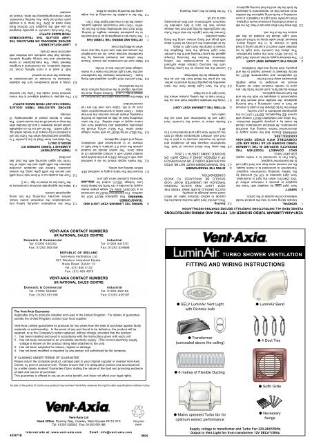
FITTING AND WIRING INSTRUCTIONS<br />
● SELV LuminAir <strong>Vent</strong> Light<br />
with Dichroic bulb<br />
● Transformer<br />
(concealed above the ceiling)<br />
● 6 metres of Flexible Ducting<br />
● Mains operated Turbo fan for<br />
optimum extract performance<br />
TURBO SHOWER VENTILATION<br />
● LuminAir Bend<br />
● 4 Duct Ties<br />
● Soffit Grille<br />
● Necessary<br />
fixings<br />
Supply voltage to transformer and Turbo Fan 220-240V/50Hz.<br />
Output to <strong>Vent</strong> Light fan from transformer 12V SELV/1/50Hz.
250<br />
Volume flow (m 3 /h)<br />
150 200<br />
*Low<br />
High<br />
PERFORMANCE<br />
50 100<br />
0<br />
0<br />
10<br />
20<br />
30<br />
40<br />
50<br />
100mm<br />
Fan static pressure (Pa)<br />
fig. 4 TURBO FAN<br />
Turbo Fan<br />
<strong>Vent</strong> Light<br />
A B C D E FØ G H I JØ<br />
mm 150 180 165 103 12 100 232 98 82 138<br />
fig. 3 DIMENSIONS<br />
<strong>Vent</strong> Light<br />
<strong>Vent</strong> Light<br />
110mmØ<br />
4 WHITE<br />
3 WHITE<br />
Flexible Ducting<br />
4 WHITE<br />
3 WHITE<br />
Flexible Ducting<br />
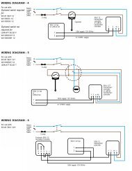
LA = High speed<br />
LB = Low speed<br />
LS N L<br />
Turbo Fan<br />
LB LA N<br />
Turbo fan<br />
1<br />
1<br />
2<br />
2<br />
N<br />
TRANSFORMER<br />
(45 29 32)<br />
N<br />
TRANSFORMER<br />
(45 29 32)<br />
L<br />
L<br />
Mounting holes 130mm dia. centres<br />
TEMPLATE FOR MOUNTING VENT-AXIA LUMINAIR<br />
Room<br />
Lighting<br />
LS<br />
L<br />
N<br />
BROWN<br />
BLUE<br />
Remote<br />
Switch<br />
Ceiling<br />
Junction<br />
Switched Live<br />
3 amp<br />
3 amp<br />
L<br />
N<br />
N<br />
L<br />
220-240V 50Hz<br />
Mains Suppy<br />
Fig.2 LuminAir SKT Turbo Shower Kit - Ref. No. 45 34 22 - White<br />
45 34 23 - Chrome<br />
45 34 24 - Gold<br />
LA = High Speed<br />
LB = Low Speed<br />
(see fig. 4 for<br />
performances)<br />
220-240V 50Hz<br />
Mains Suppy<br />
Fig.1 LuminAir SKL Turbo Shower Kit - Ref. No. 45 34 19 - White<br />
45 34 20 - Chrome<br />
45 34 21 - Gold<br />
10. WIRING DIAGRAMS