Cutting Conditions In milling
Cutting Conditions In milling
Cutting Conditions In milling

You also want an ePaper? Increase the reach of your titles
YUMPU automatically turns print PDFs into web optimized ePapers that Google loves.
Valery Marinov, Manufacturing Technology<br />
6.2 MILLING<br />
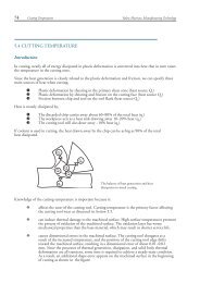
<strong>In</strong>troduction<br />
Milling 103<br />
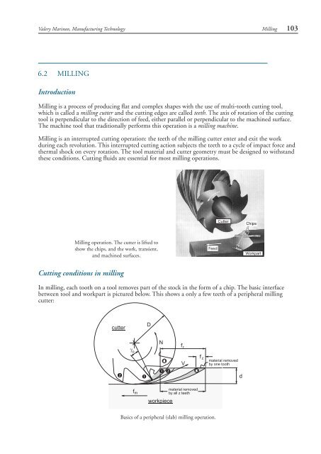
Milling is a process of producing flat and complex shapes with the use of multi-tooth cutting tool,<br />
which is called a <strong>milling</strong> cutter and the cutting edges are called teeth. The axis of rotation of the cutting<br />
tool is perpendicular to the direction of feed, either parallel or perpendicular to the machined surface.<br />
The machine tool that traditionally performs this operation is a <strong>milling</strong> machine.<br />
Milling is an interrupted cutting operation: the teeth of the <strong>milling</strong> cutter enter and exit the work<br />
during each revolution. This interrupted cutting action subjects the teeth to a cycle of impact force and<br />
thermal shock on every rotation. The tool material and cutter geometry must be designed to withstand<br />
these conditions. <strong>Cutting</strong> fluids are essential for most <strong>milling</strong> operations.<br />
Milling operation. The cutter is lifted to<br />
show the chips, and the work, transient,<br />
and machined surfaces.<br />
<strong>Cutting</strong> conditions in <strong>milling</strong><br />
<strong>In</strong> <strong>milling</strong>, each tooth on a tool removes part of the stock in the form of a chip. The basic interface<br />
between tool and workpart is pictured below. This shows a only a few teeth of a peripheral <strong>milling</strong><br />
cutter:<br />
Basics of a peripheral (slab) <strong>milling</strong> operation.
104 Milling<br />
Valery Marinov, Manufacturing Technology<br />
<strong>Cutting</strong> velocity V is the peripheral speed of the cutter is defined by<br />
V = πDN<br />
where D is the cutter outer diameter, and N is the rotational speed of the cutter.<br />
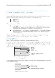
As in the case of turning, cutting speed V is first calculated or selected from appropriate reference<br />
sources (see Section 5.10 Selection of <strong>Cutting</strong> <strong>Conditions</strong>), and then the rotational speed of the cutter N,<br />
which is used to adjust <strong>milling</strong> machine controls is calculated. <strong>Cutting</strong> speeds are usually in the range of<br />
0.1~4 m/s, lower for difficult-to-cut materials and for rough cuts, and higher for non-ferrous easy-to-cut<br />
materials like aluminum and for finishing cuts.<br />
Three types of feed in <strong>milling</strong> can be identified:<br />
Types of <strong>milling</strong><br />
feed per tooth f z : the basic parameter in <strong>milling</strong> equivalent to the feed in turning.<br />
Feed per tooth is selected with regard to the surface finish and dimensional accuracy<br />
required (see Section 5.10 Selection of <strong>Cutting</strong> <strong>Conditions</strong>). Feeds per tooth are in the<br />
range of 0.05~0.5 mm/tooth, lower feeds are for finishing cuts;<br />
feed per revolution f r : it determines the amount of material cut per one full revolution<br />
of the <strong>milling</strong> cutter. Feed per revolution is calculated as<br />
f r = f z z<br />
z being the number of the cutter’s teeth;<br />
feed per minute f m : Feed per minute is calculated taking into account the rotational<br />
speed N and number of the cutter’s teeth z,<br />
f m = f z zN = f r N<br />
Feed per minute is used to adjust the feed change gears.<br />
There are two basic types of <strong>milling</strong>, as shown in the figure:<br />
down (climb) <strong>milling</strong>, when the cutter rotation is in the same direction as the motion<br />
of the workpiece being fed, and<br />
up (conventional) <strong>milling</strong>, in which the workpiece is moving towards the cutter, opposing<br />
the cutter direction of rotation:<br />
Two types of peripheral <strong>milling</strong>. Note the change in the cutting force direction.<br />
<strong>In</strong> down <strong>milling</strong>, the cutting force is directed into the work table, which allows thinner workparts to<br />
be machined. Better surface finish is obtained but the stress load on the teeth is abrupt, which may<br />
damage the cutter.<br />
<strong>In</strong> up <strong>milling</strong>, the cutting force tends to lift the workpiece. The work conditions for the cutter are<br />
more favourable. Because the cutter does not start to cut when it makes contact (cutting at zero cut is<br />
impossible), the surface has a natural waviness.
Valery Marinov, Manufacturing Technology<br />
Milling Operations<br />
Milling 105<br />
Owing to the variety of shapes possible and its high production rates, <strong>milling</strong> is one of the most<br />
versatile and widely used machining operations. The geometric form created by <strong>milling</strong> fall into three<br />
major groups:<br />
Peripheral Milling<br />
Plane surfaces: the surface is linear in all three dimensions. The simplest and most<br />
convenient type of surface;<br />
Two-dimensional surfaces: the shape of the surface changes in the direction of two<br />
of the axes and is linear along the third axis. Examples include cams;<br />
Three-dimensional surfaces: the shape of the surface changes in all three directions<br />
Examples include die cavities, gas turbine blades, propellers, casting patterns, etc.<br />
MILLING OF FLAT SURFACES<br />
<strong>In</strong> peripheral <strong>milling</strong>, also called plain <strong>milling</strong>, the axis of the cutter is parallel to the surface being<br />
machined, and the operation is performed by cutting edges on the outside periphery of the cutter. The<br />
primary motion is the rotation of the cutter. The feed is imparted to the workpiece.<br />
Several types of peripheral <strong>milling</strong> are shown in the figure,<br />
v slab <strong>milling</strong>, the basic form of peripheral <strong>milling</strong> in which the cutter width extends<br />
beyond the workpiece on both sides;<br />
v slotting, also called slot <strong>milling</strong>, in which the width of the cutter, usually called slotter,<br />
is less than the workpiece width, creating a slot in the workpiece. The slotter has<br />
teeth on the periphery and over the both end faces. When only the one-side face teeth<br />
are engaged, the operations is known as the side <strong>milling</strong>, in which the cutter machines<br />
the side of the workpiece;<br />
v straddle <strong>milling</strong>, which is the same as side <strong>milling</strong>, only cutting takes place on both<br />
sides of the work. <strong>In</strong> straddle <strong>milling</strong>, two slotters mounted on an arbor work together;<br />
v when the slotter is very thin, the operation called slitting can be used to mill narrow<br />
slots (slits) or to cut a workpart in two. The slitting cutter (slitter) is narrower than the<br />
slotter and has teeth only on the periphery.<br />
(a) (b) (c)<br />
Peripheral slab <strong>milling</strong> operation. Peripheral <strong>milling</strong> operations with narrow cutters: (a) slotting, (b)<br />
straddle <strong>milling</strong>, and (c) slitting.<br />
Some of the advantages of peripheral <strong>milling</strong> include,<br />
v More stable holding of the cutter. There is less variation in the arbor torque;<br />
v Lower power requirements;<br />
v Better work surface finish.
106 Milling<br />
Valery Marinov, Manufacturing Technology<br />
Face <strong>milling</strong><br />
<strong>In</strong> face <strong>milling</strong>, cutter is perpendicular to the machined surface. The cutter axis is vertical, but in the<br />
newer CNC machines it often is horizontal. <strong>In</strong> face <strong>milling</strong>, machining is performed by teeth on both<br />
the end and periphery of the face-<strong>milling</strong> cutter. Again up and down types of <strong>milling</strong> are available,<br />
depending on directions of the cutter rotation and feed.<br />
Partial face <strong>milling</strong> operation. The face<strong>milling</strong><br />
cutter machines only one side of<br />
the workpiece.<br />
Conventional face <strong>milling</strong> operation. The face-<strong>milling</strong> cutter<br />
machines the entire surface. The cutter diameter is greater<br />
than the workpart width.<br />
Face <strong>milling</strong> is usually applied for rough machining of large surfaces. Surface finish is worse than<br />
in peripheral <strong>milling</strong>, and feed marks are inevitable. One advantage of the face <strong>milling</strong> is the high<br />
production rate because the cutter diameter is large and as a result the material removal rate is high. Face<br />
<strong>milling</strong> with large diameter cutters requires significant machine power.<br />
End <strong>milling</strong><br />
<strong>In</strong> end <strong>milling</strong>, the cutter, called end mill, has a diameter less than the workpiece width. The end mill has<br />
helical cutting edges carried over onto the cylindrical cutter surface. End mills with flat ends (so called<br />
squire-end mills) are used to produce pockets, closed or end key slots, etc.:<br />
End <strong>milling</strong> operation used to cut a pocket in<br />
an aluminum workpart.
Valery Marinov, Manufacturing Technology<br />
MILLING OF COMPLEX SURFACES<br />
Milling 107<br />
Milling is one of the few machining operations, which are capable of machining complex two- and<br />
three-dimensional surfaces, typical for dies, molds, cams, etc. Complex surfaces can be machined either by<br />
means of the cutter path (profile <strong>milling</strong> and surface contouring), or the cutter shape (form <strong>milling</strong>).<br />
Form <strong>milling</strong><br />
<strong>In</strong> form <strong>milling</strong>, the cutting edges of the peripheral cutter (called form cutter) have a special profile that<br />
is imparted to the workpiece. Cutters with various profiles are available to cut different two-dimensional<br />
surfaces. One important application of form <strong>milling</strong> is in gear manufacturing (Section 6.6).<br />
Form <strong>milling</strong> of twodimensional<br />
surface.<br />
(Left) Profile <strong>milling</strong> of a cam, and (Right) Surface contouring<br />
of a complex three-dimensional surface.<br />
Profile <strong>milling</strong><br />
<strong>In</strong> profile <strong>milling</strong>, the conventional end mill is used to cut the outside or inside periphery of a flat<br />
part. The end mill works with its peripheral teeth and is fed along a curvilinear path equidistant from<br />
the surface profile.<br />
Surface contouring<br />
The end mill, which is used in surface contouring has a hemispherical end and is called ball-end mill.<br />
The ball-end mill is fed back and forth across the workpiece along a curvilinear path at close intervals<br />
to produce complex three-dimensional surfaces. Similar to profile <strong>milling</strong>, surface contouring require<br />
relatively simple cutting tool but advanced, usually computer-controlled feed control system.<br />
Close-up view of a hemispherical ball-end<br />
mill with indexed carbide inserts used<br />
for rough cutting of a three-dimensional<br />
surface.<br />
Surface contouring of die cavity. The cutter used is a high-speed<br />
steel ball-end mill.
108 Milling<br />
Valery Marinov, Manufacturing Technology<br />
Milling machines<br />
The conventional <strong>milling</strong> machines provide a primary rotating motion for the cutter held in the spindle,<br />
and a linear feed motion for the workpiece, which is fastened onto the worktable. Milling machines<br />
for machining of complex shapes usually provide both a rotating primary motion and a curvilinear<br />
feed motion for the cutter in the spindle with a stationary workpiece. Various machine designs are<br />
available for various <strong>milling</strong> operations. <strong>In</strong> this section we discuss only the most popular ones, classified<br />
into the following types:<br />
v Column-and-knee <strong>milling</strong> machines;<br />
v Bed type <strong>milling</strong> machines;<br />
v Machining centers.<br />
Column-and-knee <strong>milling</strong> machines<br />
The column-and-knee <strong>milling</strong> machines are the basic machine tool for <strong>milling</strong>. The name comes from<br />
the fact that this machine has two principal components, a column that supports the spindle, and a<br />
knee that supports the work table. There are two different types of column-and-knee <strong>milling</strong> machines<br />
according to position of the spindle axis:<br />
horizontal, and<br />
vertical.<br />
Two basic types of column-and-knee <strong>milling</strong> machines, (Left) horizontal, and (Right) vertical.<br />
The column-and-knee <strong>milling</strong> machine is one of the most<br />
versatile machine tool suitable for most of the <strong>milling</strong> operations.<br />
There are many modifications of the basic type, some<br />
of them allow for worktable and/or head swivelling at an<br />
angular orientation to machine angular shapes on workparts.<br />
Many of modern column-and-knee <strong>milling</strong> machines are<br />
CNC type used to machine complex shapes.<br />
CNC vertical column-and-knee<br />
<strong>milling</strong> machine.
Valery Marinov, Manufacturing Technology<br />
Bed type machines<br />
Milling 109<br />
<strong>In</strong> bed type <strong>milling</strong> machines, the worktable is mounted directly on the bed that replaces the knee.<br />
This ensures greater rigidity, thus permitting heavier cutting conditions and higher productivity. This<br />
machines are designed for mass production.<br />
Single-spindle bed machines are called simplex mills and are available in either horizontal or vertical<br />
models. Duplex mills have two spindle heads, and triplex mills add a third spindle mounted vertically<br />
over the bed to further increase machining capability.<br />
CNC vertical bed type simplex <strong>milling</strong> machine.<br />
One modification of bed type <strong>milling</strong> machines are the planer-type mills. They are the largest category of<br />
<strong>milling</strong> machine. Planer mills are designed to machine very large parts. The spindle carrier or carriers if<br />
more than one, is supported by a bridge structure (portal) that spans across the table.<br />
Portal planer mill for heavy machining of large workparts.
110 Milling<br />
Valery Marinov, Manufacturing Technology<br />
Machining centers<br />
A machining center is a highly automated machine tool capable of performing multiple machining<br />
operations under CNC control. The features that make a machining center unique include the<br />
following:<br />
v Tool storage unit called tool magazine that can hold up to 120 different cutting tools.<br />
v Automatic tool changer, which is used to exchange cutting tools between the tool<br />
magazine and machining center spindle when required. The tool changer is controlled<br />
by the CNC program.<br />
v Automatic workpart positioning. Many of machining centers are equipped with a rotary<br />
worktable, which precisely position the part at some angle relative to the spindle. It<br />
permits the cutter to perform machining on four sides of the part.<br />
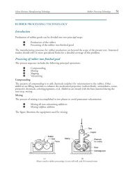
Milling cutters<br />
Universal machining center.<br />
Classification of <strong>milling</strong> cutters according to their design include the following:<br />
v HSS cutters. Many cutters like end mills, slitting<br />
cutters, slab cutters, angular cutters, form cutters,<br />
etc., are made from high-speed steel (HSS).<br />
Assortment of high-speed steel <strong>milling</strong> cutters. Highspeed<br />
steel is the cutting tool material that is used to<br />
produce cutting tools of complex designs for low to<br />
medium cutting speeds.
Valery Marinov, Manufacturing Technology<br />
Milling 111<br />
v Brazed cutters: Very limited number of cutters (mainly face mills) are made with<br />
brazed carbide inserts. This design is largely replaced by mechanically attached cutters.<br />
v Mechanically attached cutters: The vast majority of cutters are in this category. Carbide<br />
inserts are either clamped or pin locked to the body of the <strong>milling</strong> cutter.<br />
Classification of <strong>milling</strong> cutters may also be associated with the various <strong>milling</strong> operations. The figures<br />
below illustrate two of the most important types of <strong>milling</strong> cutters, end mills and ball-end mills.<br />
Two of the most widely used types of <strong>milling</strong> cutters with mechanically attached carbide inserts, (Left) end<br />
mills, and (Right) ball-end mills.<br />
Process capabilities and process planning in <strong>milling</strong> operations<br />
The surface quality and dimensional accuracy achieved in different types of <strong>milling</strong> depend on the<br />
type of <strong>milling</strong> operation. For rough cuts, the best surface finish is R a 100~50 µm, while for finishing<br />
cuts much better surface finish of R a 6.3~3.2 µm could be achieved. These values are approximate<br />
and for machining of steel. When cutting gray cast iron or non-ferrous materials, the surface finish<br />
is a grade higher.<br />
The process plan for <strong>milling</strong> of a single prismatic part includes the following basic steps:<br />
Cut off the stock slightly larger than required;<br />
Cut the basic outside dimensions to size using a <strong>milling</strong> machine;<br />
Lay out the basic features of the parts (in manual setups, this involves coating the surface<br />
with a blue stain, this is then cut and marked);<br />
Rough cut steps, radii, angles, grooves, etc.;<br />
Lay out the holes to be drilled, and then drill them starting with a center drill and<br />
gradually increasing the drill diameter;<br />
Finish cut part features;<br />
Make internal threads and ream holes if required;<br />
Deburr the finished part.<br />
For mass production, the process plan is significantly changed.