You also want an ePaper? Increase the reach of your titles
YUMPU automatically turns print PDFs into web optimized ePapers that Google loves.
84<br />
Feed Water Heater Isolation System<br />
Operation<br />
This system is designed to be “FAIL SAFE”. Failure of the<br />
controlling electric or pneumatic supplies will cause the<br />
main changeover and outlet valves to close and so<br />
isolate the feed side of the feed heater or heater bank.<br />
Float switches on feed water heaters are intended to<br />
have contacts normally made and to break with rising<br />
water level. Relays and solenoid are normally energised<br />
and are to be continuously rated.<br />
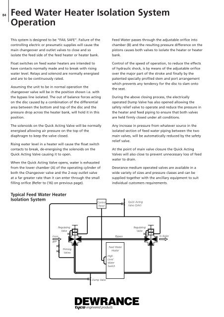
Assuming the unit to be in normal operation the<br />
changeover valve will be in the position shown i.e. with<br />
the bypass line isolated. The out of balance forces acting<br />
on the disc caused by a combination of the differential<br />
area between the bottom and top of the disc and the<br />
pressure drop across the heater bank, will hold it in this<br />
position.<br />
The solenoids on the Quick Acting Valve will be normally<br />
energised allowing air pressure on the top of the<br />
diaphragm to keep the valve closed.<br />
Rising water level in a heater will cause the float switch<br />
contacts to break, de-energising the solenoids on the<br />
Quick Acting Valve causing it to open.<br />
When the Quick Acting Valve opens, water is exhausted<br />
from the lower chamber (A) of the operating cylinder of<br />
both the Changeover valve and the 2-way outlet valve<br />
at a far greater rate than it can enter through the small<br />
filling orifice (Refer to (16) on previous page).<br />
Typical Feed Water Heater<br />
Isolation System<br />
From<br />
BFP<br />
Regulating<br />
Valve<br />
Priming<br />
Valves<br />
B<br />
A<br />
Control<br />
Panel<br />
Dump Valve<br />
Feed Water passes through the adjustable orifice into<br />
chamber (B) and the resulting pressure difference on the<br />
pistons causes both valves to isolate the heater or heater<br />
bank.<br />
Control of the speed of operation, to reduce the effects<br />
of hydraulic shock, is by means of the adjustable orifice<br />
over the major part of the stroke and finally by the<br />
patented specially profiled stem and port arrangement<br />
which prevents any tendency for the disc to slam onto<br />
the seat.<br />
During the above closing process, the electrically<br />
operated Dump Valve has also opened allowing the<br />
safety relief valve to operate and reduce the pressure in<br />
the heater and feed piping to ensure that both valves<br />
are held firmly closed under alI conditions.<br />
Any increase in pressure from whatever source in the<br />
isolated section of feed water piping between the two<br />
main valves, will be automatically reduced by the safety<br />
relief valve.<br />
At the point of main valve closure the Quick Acting<br />
Valves will also close to prevent unnecessary loss of feed<br />
water to drain.<br />
Dewrance medium operated valves are available in a<br />
wide variety of sizes and pressure classes and can be<br />
supplied together with the ancillary equipment to suit<br />
individual customers requirements.<br />
High<br />
Level<br />
Water<br />
Switch<br />
Quick Acting<br />
Valve (DAV)<br />
Regulating<br />
Valve B<br />
Bypass<br />
A<br />
To Boiler<br />
Feed Water<br />
Heater


