158QGDA-15RAB-SU-RS RIGHT ANGLE DRILLS - Apex Tool Group
158QGDA-15RAB-SU-RS RIGHT ANGLE DRILLS - Apex Tool Group
158QGDA-15RAB-SU-RS RIGHT ANGLE DRILLS - Apex Tool Group

You also want an ePaper? Increase the reach of your titles
YUMPU automatically turns print PDFs into web optimized ePapers that Google loves.
<strong>158QGDA</strong>-<strong>15RAB</strong>-<strong>SU</strong>-<strong>RS</strong><br />
<strong>RIGHT</strong> <strong>ANGLE</strong> <strong>DRILLS</strong><br />
Houston Operation<br />
7007 Pinemont<br />
Houston, TX 77040<br />
Operation & Service Manual<br />
823200 1/02<br />
Recoules Operation<br />
Zone industrielle - B.P. 28<br />
Avenue Maurice Chevalier<br />
77831 Ozoir-la-Ferriere Cedex France<br />
1
Safety Recommendations<br />
For your safety and the safety of others, read and understand<br />
the safety recommendations and operating instructions.<br />
Always wear protective equipment:<br />
For additional information on eye and face protection, refer to<br />
Federal OSHA Regulations, 29 Code of Federal Regulations, Section<br />
1910.133., Eye and Face Protection, and American National<br />
Standards Institute, ANSI Z87.1, Occupational and Educational Eye<br />
and Face Protection. Z87.1 is available from the American National<br />
Standards Institute, Inc., 11 West 42nd Street, New York, N.Y.<br />
10036.<br />
Hearing protection is recommended in high noise areas, 85 dBA or<br />
greater. The operation of other tools and equipment in the area,<br />
reflective surfaces, process noises and resonant structures can<br />
substantially contribute to and increase the noise level in the area.<br />
For additional information on hearing protection, refer to Federal<br />
OSHA Regulations, 29 Code of Federal Regulations, Section 1910.95,<br />
Occupational Noise Exposure, and American National Standards<br />
Institute, ANSI S12.6, Hearing Protectors.<br />
2<br />
!<br />
Do not wear loose fitting clothes,<br />
long hair, gloves, ties or jewelry.<br />
!<br />
WARNING<br />
Impact resistant eye protection<br />
must be worn while operating<br />
or working near this tool.<br />
!<br />
WARNING<br />
CAUTION<br />
Personal hearing protection is<br />
recommended when operating<br />
or working near this tool.<br />
Follow good machine shop<br />
practices. Rotating shafts and<br />
moving components entangle<br />
and entrap, and may result in<br />
serious injuries. Never wear<br />
long hair, loose-fitting clothes,<br />
gloves, ties, or jewelry when<br />
working with or near a drill of<br />
any type.<br />
!<br />
CAUTION<br />
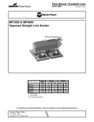
• Quackenbush drills are designed to operate on 90psig (6.2 bar)<br />
air pressure. Excessive air pressure can increase the loads and<br />
stresses on tool parts and drills, and may result in breakage. The<br />
installation of a filter-regulator-lubricator in the air supply line is<br />
highly recommended.<br />
• Before removing a tool from service or changing drill bits, make<br />
sure the air line is shut off and drained of air. This will prevent the<br />
tool from operating if the throttle is accidently engaged.<br />
• Cutting tools used with these Quackenbush drill motors are sharp.<br />
Handle them carefully to avoid injury.<br />
!<br />
CAUTION<br />
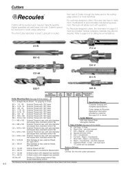
Before mounting any positive feed drill, check the lock screws in the<br />
tooling fixture and drill bushing. Make sure both are in good condition<br />
and securely tightened.<br />
Lock Screws<br />
<strong>Tool</strong>ing Fixture<br />
Standard Threaded<br />
Drill Bushing<br />
<strong>Tool</strong> Nose<br />
Positive feed drills can exert high torques and high thrust loads. If<br />
failure of the lock screws or drill bushing occurs, the drill may<br />
suddenly spin and back away from the drill fixture.<br />
Warning Labels<br />
The warning labels found on these tools are essential parts of this<br />
product. Labels should not be removed. Labels should be checked<br />
periodically for legibility. Replace warning labels when missing or<br />
when the information can no longer be read. Replacement labels<br />
can be ordered from the manufacturer.
Safety Recommendations<br />
!<br />
The spindle on right angle positive feed drills retracts at a much<br />
faster rate than it feeds. Care should be taken to avoid entrapment.<br />
Nose pieces usually used with these drills are generally slotted for<br />
visibility and access to chuck, cutter, and retract stop adjustments.<br />
A spindle guard should be used when operating tool. Spindle<br />
guards in one inch increments are available to accommodate any<br />
length spindle. Slotted spindle guards are available for tools with<br />
fluid swivels.<br />
Drilling or other use of this tool may produce hazardous fumes and/<br />
or dust. To avoid adverse health effects utilize adequate ventilation<br />
and/or a respirator. Read the material safety data sheet for any<br />
cutting fluids or materials involved in the drilling process.<br />
!<br />
CAUTION<br />
!<br />
!<br />
WARNING<br />
WARNING<br />
Keep hands and fingers away from<br />
slot in spindle guard and nose piece<br />
when handling or operating tool.<br />
WARNING<br />
Wear respirator where<br />
necessary.<br />
• Most dusts are combustible. See material safety data sheets for<br />
combustibility of a specific dust.<br />
• Non ferrous metal dusts are particularly haxardous.<br />
Examples: Aluminum, Magnesium, Titanium, Zirconium<br />
(Never collect Magnesium in a dry dust collector)<br />
• Never collect spark generating material in the same dust collector<br />
with combustible material.<br />
Examples: Collecting both Steel and Aluminum dust or Steel and<br />
Titanium dust.<br />
• Never use flamable finishing lubricants.<br />
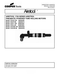
Some individuals are susceptible to disorders of the hands and arms<br />
when exposed to tasks which involve repetitive work motions. Those<br />
individuals predisposed to vasculatory or circulatory problems may<br />
be particularly susceptible. Cumulative trauma disorders such as<br />
carpal tunnel syndrome and tendinitis may be caused or aggravated<br />
by repetitious, forceful exertions of the hands and arms. These<br />
disorders develop gradually over periods of weeks, months, and<br />
years.<br />
Avoid OK Avoid Avoid OK Avoid<br />
Extension Neutral Flexion Radial Deviation Neutral Ulnar Deviation<br />
• Tasks should be performed in such a manner that the wrists<br />
are maintained in a neutral position, which is not flexed,<br />
hyperextended, or turned side to side.<br />
• Stressful postures should be avoided and can be controlled<br />
through tool selection and work location.<br />
Any tool operator should be aware of the following warning signs and<br />
symptoms so that a problem can be addressed before it becomes a<br />
debilitating injury. Any user suffering prolonged symptoms of tingling,<br />
numbness, blanching of fingers, clumsiness or weakened<br />
grip, nocturnal pain in the hand, or any other disorder of the<br />
shoulders, arms, wrists, or fingers is advised to consult a physician.<br />
If it is determined that the symptoms are job related or aggravated<br />
by movements and postures dictated by the job design, it may be<br />
necessary for the employer to take steps to prevent further occurrences.<br />
These steps might include, but are not limited to, repositioning<br />
the workpiece or redesigning the workstation, reassigning workers<br />
to other jobs, rotating jobs, changing work pace, and/or changing<br />
the type of tool used to minimize stress on the operator. Some tasks<br />
may require more than one type of tool to obtain the optimum<br />
operator/tool/task relationship.<br />
The following recommendations will help reduce or moderate the<br />
effects of repetitive work motions. The operator of any drill should:<br />
• Use a minimum hand grip force consistent with proper control and<br />
safe operation<br />
• Keep body and hands warm and dry<br />
• Avoid anything that inhibits blood circulation<br />
— Smoking Tobacco<br />
— Cold Temperatures<br />
— Certain Drugs<br />
• Avoid awkward postures<br />
• Keep wrists as straight as possible<br />
• Interrupt work activities, or rotate jobs to provide periods free from<br />
repetitive work motions.<br />
3
4<br />
The tool is designed to operate on 90 psig air pressure using<br />
a 1/2 inch l.D. hose up to 8 feet in length. If additional length<br />
is required, a 5/8 inch l.D. or larger hose should be connected<br />
to the 1/2 inch hose.<br />
NOTE: Safety Labels can be ordered using part no. 202691.<br />
The tool is started by turning the trigger 613697 to the on<br />
position.<br />
The feed cycle is started by pushing the retract lever 622973<br />
down. The spindle may be controlled by the Automatic Stop<br />
or it may be manually retracted at any point by pulling the<br />
retract lever up. Rapid retraction of the spindle takes place<br />
while the spindle continues to rotate.<br />
NOTE: The Gear Stop 622985 can be adjusted by turning<br />
the two 1/8" hex set screws 867502 on either side of the<br />
angle head.<br />
Before installing or removing a cutting tool, or accessory, be<br />
sure the tool is disconnected from the air supply. If the air<br />
supply line has a valve, shut the valve off and bleed off the<br />
air in the line.<br />
LUBRICATlON<br />
An automatic in-line filter-regulator-lubricator is recommended<br />
as it increases tool life and keeps the tool in<br />
sustained operation. The in-line lubricator should be regularly<br />
checked and filled with a good grade of 10W machine<br />
oil. Proper adjustment of the in-line lubricator is performed<br />
by placing a sheet of paper next to the exhaust ports and<br />
holding the throttle open approximately 30 seconds. The<br />
lubricator is properly set when a light stain of oil collects on<br />
the paper. Excessive amounts of oil should be avoided.<br />
STORAGE<br />
In the event that it becomes necessary to store the tool for<br />
an extended period of time (overnight, weekend, etc.), it<br />
should receive a generous amount of lubrication at that time<br />
and again when returned to service. The tool should be<br />
stored in a clean and dry environment.<br />
GENERAL<br />
OPERATING & SERVICE INSTRUCTIONS<br />
Clamp the tool lightly on the flats of the motor housing in a<br />
soft jawed vise and unscrew the drill head from the power<br />
unit.<br />
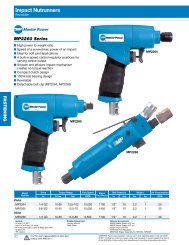
POWER UNIT<br />
To remove the motor unit from the motor housing, invert the<br />
tool in the vise. Loosen the handle nut 613283 and remove<br />
the handle. The complete motor unit may now be slipped out<br />
through the rear of the motor housing. Unscrew the governor<br />
( Left Hand Threads) and remove the rear bearing plate<br />
613241 from the shaft. Remove the rotor shaft retainer<br />
843618 and using a soft mallet tap the rotor shaft out of the<br />
front rotor bearing 613248. This will allow the front bearing<br />
plate 613273, the cylinder 613225, rotor blades 613236,<br />
and the rotor 613234, to be removed. Remove the two (2)<br />
keys 863365, from the rotor shaft 624294, and clamp it in the<br />
vise with the governor up. To remove the front rotor bearing<br />
from the front bearing plate for inspection, the rotor bearing<br />
retainer 613294, (Left Hand Treads) must be unscrewed<br />
first.<br />
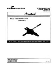
DISASSEMBLY AND REASSEMBLY DRILL HEAD<br />
Unscrew (Left Hand Threads) and remove the drill head<br />
from the power unit To disassemble the drill head slip the<br />
spacer 617149 out of the rear of the head. This will allow the<br />
ball bearing No 847095 and bevel gear 622947 to be<br />
removed.<br />
Unscrew the four (4) retract body screws 863337 and<br />
remove the retract body 624094 and attached components.<br />
Loosen the stop collar screw 617785 and unscrew the stop<br />
collars 617962 (Left Hand Threads). Removing the nose<br />
adapter (Left Hand Threads) will allow the spindle and<br />
attached parts to be removed from the drill head.<br />
Unscrew the four (4) cover screws and remove the cover<br />
625092 and attached parts. The drill head is reassembled<br />
in the reverse order of disassembly. All parts should be<br />
carefully inspected for evidence of wear. Damaged or worn<br />
parts should be replaced where necessary. As all of the<br />
various gears and bearings are being assembled they<br />
should be coated with a generous amount of LUBRIPLATE<br />
#907 GREASE. When installing the bearing 617168, the<br />
ball loading notches should be facing up.<br />
During reassembly be sure that the rotor shaft 624294 is<br />
engaged in the drill head.
<strong>RIGHT</strong> <strong>ANGLE</strong> HEAD<br />
5
6<br />
PART NO.<br />
613828<br />
614574<br />
614575<br />
617149<br />
617166<br />
617168<br />
617785<br />
617962<br />
617980<br />
617993<br />
619016<br />
622400<br />
622401<br />
622946<br />
622947<br />
622948<br />
622949<br />
622950<br />
622952<br />
622954<br />
622973<br />
622976<br />
622978<br />
622980<br />
622984<br />
622985<br />
622986<br />
623000<br />
623001<br />
623002<br />
623003<br />
624094<br />
624295<br />
624351<br />
624355<br />
625092<br />
834228<br />
842161<br />
844111<br />
844247<br />
844265<br />
844306<br />
844787<br />
847095<br />
847430<br />
847609<br />
863337<br />
863463<br />
865576<br />
867502<br />
NAME OF PART<br />
PART LISTS — DRILL HEAD<br />
Name Plate<br />
Idler Gear Spacer (Long)<br />
Idler Gear Spacer (Short)<br />
Spacer<br />
Flat Head Screw (6/32" x 5/8")<br />
Feed Gear Ball Bearing<br />
Stop Collar Set Screw<br />
Stop Collar<br />
Ball Bearing<br />
Spring<br />
Retainer Ring<br />
Ball Bearing<br />
Nose Adapter<br />
Driven Bevel Gear<br />
Driving Bevel Gear<br />
Idler Gear<br />
Differential Drive Gear<br />
Spindle Drive Gear<br />
Pinion & Shaft<br />
Ball Plunger<br />
Retract Lever<br />
Drive Gear Retainer Screw<br />
Dowel Pin<br />
Idler Gear Shaft<br />
Clutch Roller<br />
Gear Stop<br />
Housing<br />
.0005" Differential Feed Gear (34T)<br />
.0005" Spindle Feed Gear (37T)<br />
.001" Spindle Feed Gear (43T)<br />
.001" Differential Feed Gear (40T)<br />
Retract Body<br />
Angle Head Adapter<br />
Fluid Spindle Guard Shims (.010")<br />
Spindle Guard Cap**<br />
Cover<br />
Drive Screw<br />
Steel Ball (3/16")<br />
Lever Pin<br />
Roller Spring<br />
Steel Ball (1/8")<br />
"O"-Ring 5/16" x 7/16"<br />
Roll Pin<br />
Bevel Gear Ball Bearing<br />
Drive Gear Needle Bearing<br />
Pinion Shaft Ball Bearing<br />
Socket Head Cap Screw<br />
Flat Head Screw (6/32" x 3/8")<br />
Thrust Race<br />
Set Screw<br />
**Included with Spindle Guards<br />
Drill Head Assemblies<br />
Feed<br />
.0005"<br />
.001"<br />
Code No.<br />
631242<br />
631240<br />
QUANITY<br />
1<br />
1<br />
1<br />
1<br />
2<br />
1<br />
2<br />
2<br />
1<br />
1<br />
2<br />
1<br />
1<br />
1<br />
1<br />
1<br />
1<br />
1<br />
1<br />
2<br />
1<br />
1<br />
2<br />
1<br />
4<br />
1<br />
1<br />
1<br />
1<br />
1<br />
1<br />
1<br />
1<br />
1<br />
4<br />
1<br />
2<br />
1<br />
1<br />
2<br />
1<br />
1<br />
1<br />
2<br />
1<br />
1<br />
4<br />
2<br />
1<br />
2
MOTOR UNIT<br />
PART NO. NAME OF PART QTY. PART NO. NAME OF PART<br />
QTY.<br />
613102<br />
613109<br />
613110<br />
613162<br />
613225<br />
613234<br />
613236<br />
613241<br />
613242<br />
613248<br />
613253<br />
613254<br />
613273<br />
613275<br />
613282<br />
613283<br />
613294<br />
613367<br />
613368<br />
613372<br />
Hose Adaptor<br />
Gasket<br />
Screen<br />
Cylinder Pin<br />
Cylinder<br />
Rotor<br />
Rotor Blade<br />
Rear Bearing Plate<br />
Sleeve<br />
Front Rotor Bearing<br />
Throttle Valve Washer<br />
Throttle Valve (Incl. 812165)<br />
Front Bearing Plate<br />
Motor Housing<br />
Clamp Ring<br />
Handle Nut<br />
Bearing Retainer Nut<br />
Retainer Ring<br />
Governor Spring<br />
Governor Weight<br />
613374<br />
613375<br />
613376<br />
613377<br />
613378<br />
613688<br />
613697<br />
615391<br />
615466<br />
615467<br />
617397<br />
619987<br />
624294<br />
812165<br />
812231<br />
843618<br />
844111<br />
844265<br />
844308<br />
847511<br />
863365<br />
Governor Weight Pin<br />
Governor Spider<br />
Governor Valve<br />
Governor Spring Cap<br />
Governor Spring Retainer<br />
Throttle Valve Bushing<br />
Trigger<br />
Exhaust Deflector<br />
Wire Screen (Inner)<br />
Wire Screen (Outer)<br />
Backhead (Incl. 613688, 619987)<br />
Governor Jet<br />
Rotor Shaft<br />
Stop Pin<br />
Retainer Ring<br />
Retainer Ring<br />
Trigger Pin<br />
Steel Ball (1/8")<br />
"O" Ring 3/8" X 9/16"<br />
Rear Rotor Bearing<br />
Rotor Shaft Key<br />
The complete backhead can be purchased as subassembly using the following part number: 611185<br />
1<br />
1<br />
1<br />
1<br />
1<br />
1<br />
4<br />
1<br />
1<br />
1<br />
1<br />
1<br />
1<br />
1<br />
1<br />
1<br />
1<br />
1<br />
1<br />
2<br />
2<br />
1<br />
1<br />
1<br />
1<br />
1<br />
1<br />
1<br />
1<br />
1<br />
1<br />
1<br />
1<br />
1<br />
1<br />
1<br />
1<br />
2<br />
2<br />
1<br />
2<br />
7
8<br />
Cooper<strong>Tool</strong>s<br />
7007 Pinemont<br />
Houston, Texas 77040<br />
Phone: (713) 462-4521<br />
Fax: (713) 460-7008<br />
www.cooperindustries.com