
You also want an ePaper? Increase the reach of your titles
YUMPU automatically turns print PDFs into web optimized ePapers that Google loves.
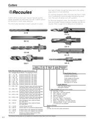
E SERIES RIVETERS<br />
16 SERIES CHIPPERS<br />
Series:<br />
E2<br />
E3<br />
E4<br />
E5<br />
16<br />
Handle Style:<br />
AJ Lever<br />
BWD Offset<br />
Nose Type :<br />
RD<br />
HX<br />
RT<br />
Retainer :<br />
B<br />
O<br />
(2 1/4 Stroke)<br />
(3" Stroke)<br />
(4" Stroke)<br />
(5" Stroke)<br />
(1 7/16 Stroke)<br />
Round<br />
Hexagon<br />
Round Taper<br />
Beehive<br />
Open Coil<br />
XX - XXX - XX - X<br />
NORTH AMERICA EUROPE<br />
Cooper<strong>Tool</strong>s<br />
P.O. Box 1410<br />
Lexington, SC 29071<br />
Operation & Service Manual<br />
823046 7/01<br />
Cooper Power <strong>Tool</strong>s GmbH & Co.<br />
Postfach 30<br />
D-73461 Westhausen<br />
1
2<br />
Safety Recommendations<br />
For your safety and the safety of others, read and understand<br />
the safety recommendations before operating any percussion<br />
tool.<br />
Always wear protective equipment and clothing.<br />
!<br />
WARNING<br />
Impact resistant eye protection<br />
must be worn while operating<br />
or working near this tool.<br />
Caution:<br />
Faceshields<br />
do not provide<br />
unlimited prot<br />
e c t i o n<br />
against flying<br />
particles and are not to be considered as eye protection. ANSI<br />
Z87.1 states that separate eyewear shall be used. For additional<br />
information on eye protection, refer to Federal OSHA<br />
Regulations, 29 CFR, Section 1910.133, Eye and Face<br />
Protection, and ANSI Z87.1, Occupational and Educational<br />
Eye and Face Protection. This standard is available from the<br />
American National Standards Institute, Inc., 11 West 42nd<br />
street, New York, NY 10036.<br />
!<br />
CAUTION<br />
Personal hearing protection is<br />
recommended when operating<br />
or working near this tool.<br />
Hearing protection<br />
is recommended<br />
in high noise<br />
areas (above<br />
85 dBA).<br />
Close proximity of additional tools, reflective surfaces, process<br />
noises, and resonant structures can substantially contribute<br />
to the sound level experienced by the operator. Proper<br />
hearing conservation measures, including annual audiograms<br />
and training in the use and fit of hearing protection devices<br />
may be necessary. For additional information on hearing<br />
protection, refer to Federal OSHA Regulations, 29 CFR,<br />
Section 1910.95, Occupational Noise Exposure, and American<br />
National Standards Institute, ANSI S12.6, Hearing Protectors.<br />
Gloves and other protective clothing should be worn as<br />
required. Properly fitted gloves cushion vibration and protect<br />
the fingers from pinching, scuffing and scraping and must be<br />
used when guiding the chisel on a workpiece.<br />
!<br />
WARNING<br />
Compressed air hazard.<br />
Compressed air can cause loss<br />
of eyesight, bleeding or injection<br />
of foreign material into the body<br />
or blood.<br />
Never use compressed air to clean<br />
off clothing or direct it at any person.<br />
Cleco percussion tools are designed to operate on 90 psig<br />
(6.2 bar) maximum air pressure. Excessive air pressure can<br />
damage the plunger and increases sound levels. Installation<br />
of a filter-regulator-lubricator in the air supply line ahead of<br />
the tool is highly recommended. Before the tool is connected<br />
to the air supply, check the throttle for proper operation (i.e.,<br />
throttle moves freely and returns to closed position). Being<br />
careful not to endanger adjacent personnel, clear the air hose<br />
of accumulated dust and moisture. Attachment of a quickdisconnect<br />
air coupling directly to the inlet threads of a<br />
percussion tool can cause wear and failure of the coupling.<br />
Should the coupling fail, severe injury can result from the<br />
hose end violently whipping about. If a quick-disconnect air<br />
coupling is used, separate the coupling from the tool with a<br />
whip hose (1.5 feet minimum). Only use a whip hose with<br />
fittings of hardened steel or other material which is at least<br />
comparably resistant to shock. Do not use hose to lift or lower<br />
tool.<br />
Do not use!<br />
Coupling Nipple<br />
Quick Disconnect<br />
Coupling<br />
Coupling Nipple<br />
Quick Disconnect<br />
Coupling<br />
Cracked chisels or implements are<br />
!<br />
WARNING hazardous. Visually inspect the chisel<br />
or implement for cracks before use.<br />
Make a practice of having all chisels magnifluxed before<br />
resharpening. Destroy and discard any chisel or implement<br />
that shows a crack.<br />
!<br />
Correct selection of the chisel or other implement is important.<br />
Dull edges on the chisel or moil point cause the energy<br />
of the percussion blow to be absorbed by the tool itself,<br />
instead of the workpiece, increasing the chance of chisel<br />
breakage. When operating percussion tools in explosive or<br />
flammable environments, use only non-sparking chisels or<br />
implements such as those made from beryllium copper. Also,<br />
do not use cupped rivet sets with Cleco percussion tools to<br />
drive nails. Blows not centered on the nail can cause the nail<br />
to ricochet off the work and strike the user.<br />
OK<br />
WARNING<br />
Explosive Hazard.<br />
Do not use this tool in explosive<br />
or flammable environment.<br />
Whip Hose
Safety Recommendations<br />
Before removing a tool from service, after completing a job,<br />
or changing chisels or other bits, make sure the air line is shut<br />
off and drained of air. This will prevent the tool from operating<br />
if the throttle is accidently engaged. Use of a self-relieving<br />
valve within reach of the user of the tool is highly recommended.<br />
INDIVIDUAL WORK STATION<br />
Self-Relieving<br />
Valve<br />
Filter<br />
Hose<br />
Quick Disconnect<br />
Coupling<br />
0<br />
90<br />
45<br />
!<br />
Impact Hazard. Ejected chisels can cause<br />
serious injury or even death.<br />
Disconnect air before changing chisels.<br />
Do not operate unless chisel is in contact<br />
with workpiece.<br />
Do not point tool in direction of any person.<br />
Use safety retainers on tool and retainer<br />
type chisels.<br />
Regulator<br />
WARNING<br />
Erect barriers to protect persons in<br />
surrounding or lower work areas.<br />
<strong>Tool</strong><br />
Lubricator<br />
Coupling<br />
Do not operate or trigger any percus-<br />
!<br />
WARNING sion tool unless the chisel, scaling tool,<br />
rivet set, or other implement is in the<br />
tool and in contact with the workpiece or worksurface. Never<br />
point any percussion tool in the direction of another person or<br />
yourself, or deliberately eject a chisel. Failure to do so can<br />
cause serious injury and/or damage the tool.<br />
Chisel or rivet set retainers are recommended and furnished<br />
as standard equipment. Periodic inspection of the retainer<br />
for wear or damage is recommended since these devices<br />
can receive heavy abuse, particularly if the tool is run off<br />
the workpiece. Damaged retainers are dangerous, and<br />
can allow the ejection of a chisel or other implement.<br />
They must be replaced as necessary. Only use safety<br />
retainer type chisels, as shown in the operating instructions<br />
and service manual. Also, it is good safety practice to<br />
erect suitable barriers to protect persons in surrounding or<br />
lower work areas from possible ejected tools.<br />
!<br />
WARNING<br />
Repetitive work motions and/or<br />
vibration can cause injury to<br />
hands and arms.<br />
Use minimum hand grip force<br />
consistant with proper control<br />
and safe operation. Keep body<br />
and hands warm and dry. Avoid<br />
anything that inhibits blood circulation.<br />
Avoid continuous vibration exposure.<br />
Keep wrists straight.<br />
Avoid repeated bending of wrists<br />
and hands.<br />
Some individuals may be susceptible to disorders of the<br />
hands and arms when performing tasks consisting of highly<br />
repetitive motions and/or exposure to extended vibration.<br />
Cumulative trauma disorders such as carpal tunnel syndrome<br />
and tendonitis may be caused or aggravated by<br />
repetitious, forceful exertions of the hands and arms. Vibration<br />
may contribute to a condition called Raynaud’s Syndrome.<br />
These disorders develop gradually over periods of<br />
weeks, months, and years. It is presently unknown to what<br />
extent exposure to vibrations or repetitive motions may contribute<br />
to the disorders. Hereditary factors, vasculatory or<br />
circulatory problems, exposure to cold and dampness, diet,<br />
smoking and work practices are thought to contribute to the<br />
conditions.<br />
Any tool operator should be aware of the following <strong>warning</strong><br />
signs and symptoms so that a problem can be addressed<br />
before it becomes a debilitating injury. Any user suffering<br />
prolonged symptoms of tingling, numbness, blanching of<br />
fingers, clumsiness or weakened grip, nocturnal pain in the<br />
hand, or any other disorder of the shoulders, arms, wrists, or<br />
fingers is advised to consult a physician. If it is determined<br />
that the symptoms are job related or aggravated by movements<br />
and postures dictated by the job design, it may be<br />
necessary for the employer to take steps to prevent further<br />
occurrences. These steps might include, but are not limited<br />
to, repositioning the workpiece or redesigning the workstation,<br />
reassigning workers to other jobs, rotating jobs, changing<br />
work pace, and/or changing the type of tool used so as to<br />
minimize stress on the operator. Some tasks may require<br />
more than one type of tool to obtain the optimum operator/<br />
tool/task relationship.<br />
BAD POSTURE<br />
GOOD POSTURE<br />
3
4<br />
Safety Recommendations<br />
The following suggestions will help reduce or moderate the<br />
effects of repetitive work motions and/or extended vibration<br />
exposure:<br />
Use a minimum hand grip force consistent with<br />
proper control and safe operation<br />
Keep body and hands warm and dry (cold weather is<br />
reported to be a major factor contributing to<br />
Raynaud's Syndrome)<br />
Avoid anything that inhibits blood circulation<br />
—Smoking Tobacco (another contributing factor)<br />
—Cold Temperatures<br />
—Certain Drugs<br />
Tasks should be performed in such a manner that<br />
the wrists are maintained in a neutral position, which<br />
is not flexed, hyperextended, or turned side to side<br />
Stressful postures should be avoided — select a tool<br />
appropriate for the job and work location<br />
Avoid highly repetitive movements of hands and<br />
wrists, and continuous vibration exposure (after each<br />
period of operation, exercise to increase blood<br />
circulation)<br />
Use quality abrasive wheels (the primary source of<br />
vibration when using a grinder is a wheel that is out<br />
of balance, out of round, untrue, or possibly any<br />
combination of all three)<br />
Keep tool well maintained and replace worn parts (a<br />
preventive maintanance program with scheduled<br />
inspec tions is highly recommended)<br />
Work gloves with vibration reducing liners and wrist supports<br />
are available from some manufacturers of industrial work<br />
gloves. <strong>Tool</strong> wraps and grips are also available from a<br />
number of different manufacturers. These gloves, wraps, and<br />
wrist supports are designed to reduce and moderate the<br />
effects of extended vibration exposure and repetitive wrist<br />
trauma. Since they vary widely in design, material, thickness,<br />
vibration reduction, and wrist support qualities, it is recommended<br />
that the glove, tool wrap, or wrist support manufacturer<br />
be consulted for items designed for your specific application.<br />
!<br />
WARNING<br />
Proper fit of gloves is important.<br />
Improperly fitted gloves may restrict<br />
blood flow to the fingers and can<br />
substantially reduce grip strength.<br />
This information is a compilation of general safety practices<br />
obtained from various sources available at the date of production.<br />
However, our company does not represent that<br />
every acceptable safety practice is considered herein, or that<br />
abnormal or unusual circumstances may not warrant or<br />
require additional procedures. Your work may require additional<br />
specific safety procedures. Follow these procedures as<br />
required by your company. For more information, see the<br />
latest edition of ANSI B186.1, Safety Code for Portable Air<br />
<strong>Tool</strong>s, available from the American National Standards Institute,<br />
Inc., 11 West 42nd street, New York, NY 10036.
!<br />
WARNING<br />
Eye protection must be worn when disassembling tool or when air line is<br />
turned on. A self-relieving valve in close proximity to the repair station to<br />
bleed off air is recommended.<br />
The CLECO "E" series riveters and "16" series<br />
chippers are designed to operate on 90 psig air<br />
pressure using a 5/16" I.D. hose up to 8' in<br />
length. If additional length is required, a 3/8" I.D.<br />
or larger hose should be connected to the 5/16"<br />
hose.<br />
The air hose should be cleared of accumulated<br />
dirt and moisture, then one-half (1/2) teaspoon<br />
of 10W machine oil should be poured into the<br />
tool's air inlet before connecting the hose to the<br />
tool.<br />
Important: The handle should be checked after<br />
the first eight hours of operation and occasionally<br />
thereafter to make sure it is tight.<br />
LUBRICATION<br />
An automatic in-line filter-regulator-lubricator is<br />
recommended as it increases tool life and keeps<br />
the tool in sustained operation. The in-line lubricator<br />
should be regularly checked and filled with<br />
a good grade of 10W machine oil. Never use a<br />
heavy oil, as this will cause a loss of efficiency.<br />
Proper adjustment of<br />
the in-line lubricator<br />
is performed by placing<br />
a sheet of paper<br />
next to the exhaust<br />
ports and holding the<br />
throttle open for approximately<br />
30 seconds.<br />
The lubricator<br />
is properly set when<br />
a light stain of oil collects<br />
on the paper.<br />
Excessive amounts<br />
of oil should be<br />
avoided.<br />
If the operation of the chipper becomes sluggish<br />
or erratic, pour one teaspoon of kerosene into<br />
OPERATING INSTRUCTIONS<br />
the air inlet and operate the tool for a few<br />
seconds. Lubricate the tool as explained above<br />
after flushing.<br />
STORAGE<br />
In the event that it becomes necessary to store<br />
the tool for an extended period of time (overnight,<br />
weekend, etc.), it should receive a generous<br />
almount of lubrication at that time and again<br />
when returned to service. Store the tool in a<br />
clean and dry environment. Alternatively, chippers<br />
and scalers may be put in a bucket of<br />
kerosene or light oil for extended periods of<br />
storage such as weekends or plant shutdowns.<br />
The tool should always be lubricated before<br />
storage and when being returned to service.<br />
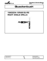
CHISEL or RIVET SET INSTALLATION & RE-<br />
MOVAL<br />
!<br />
WARNING<br />
Turn off the air and drain the<br />
air hose before installing or<br />
removing any chisel or implement. Follow the<br />
procedure below for installing any chisel or<br />
implement. Reverse the procedure for removal.<br />
"E" & "16" CHISEL or RIVET SET INSTALLATION & REMOVAL<br />
Pushing on tab in a<br />
counterclockwise direction,<br />
unscrew the retainer off<br />
the barrel.<br />
RETAINER<br />
CHISEL or<br />
RIVET SET<br />
Insert into<br />
barrel.<br />
BARREL<br />
5
6<br />
!<br />
WARNING<br />
DISASSEMBLY<br />
Eye protection must be worn when disassembling tool or when air line is<br />
turned on. A self-relieving valve in close proximity to the repair station to<br />
bleed off air is recommended.<br />
To disassemble the tool, remove the tool retainer<br />
No. 832953, and place the flats of the<br />
barrel in a vise with the handle facing upward.<br />
Remove the handle locking clip No. 832565,<br />
and unscrew the handle. The complete valve<br />
assembly can now be removed from the rear of<br />
the barrel. Remove the barrel from the vise and<br />
invert it to remove the plunger.<br />
Check the following paragraphs for the disassembly<br />
instructions on the particular handle<br />
being used on the tool.<br />
AJ HANDLE<br />
Clamp the handle No. 832802, in the vise and<br />
using a suitable punch, drive out the throttle<br />
lever pin No. 844653. This will allow the throttle<br />
lever No. 832142, to be removed. Unscrewing<br />
the throttle valve cap No. 832207, allows the<br />
throttle valve mechanism to drop out. Remove<br />
the inlet bushing No. 841553, for cleaning and<br />
inspection of the air screen.<br />
BWD HANDLE<br />
Clamp the handle No. 869972, in the vise with<br />
the inlet bushing No. 867916, up. Unscrewing<br />
the inlet bushing will allow the throttle valve<br />
mechanism to drop out.<br />
SERVICE INSTRUCTIONS<br />
REASSEMBLY<br />
The tool is reassembled in the reverse order of<br />
disassembly. Wash all parts thoroughly in a<br />
solvent before reassembly. Seals and "O"-Rings<br />
should be replaced if they are damaged or<br />
deteriorated in any way. Prepare the threads on<br />
the barrel and in the handle with a high grade<br />
thread lubricant before assembling. Make sure<br />
the threads are clean before lubricating. If a new<br />
throttle pin bushing is installed in the handle, it<br />
should be reamed to fit the throttle valve pin. The<br />
screen in the inlet bushing should be blown out<br />
in the reverse of normal air flow.<br />
Install the throttle valve cap No. 832207, into the<br />
"AJ" handle with Locktite No. 271.<br />
All air passages in the barrel and valve assembly<br />
should be checked to make sure that they<br />
are not clogged with any dirt or foreign matter.<br />
After reassembly, place teaspoon of 10W machine<br />
oil in the handle bushing before attaching<br />
the air hose. This will insure immediate lubrication<br />
of all parts as soon as the air is applied.<br />
Check the operation of the tool before installing<br />
the handle locking clip No. 832565.
PARTS LIST— "E" RIVETERS<br />
Part No. Name of part Qty. Part No. Name of part Qty.<br />
202013 Valve Button Pin (Lower) 1 832456 <strong>Tool</strong> Nose (G-hex)-Opt. 832378<br />
812165 Valve Button Oin (Upper) 1 832462 <strong>Tool</strong> Nose (GP)-Opt. 832453<br />
832176 Valve Block Button<br />
1 832514 Valve Block<br />
832456<br />
832198 Valve<br />
1 832565 Handle Locking Clip 832462<br />
832225 Locking Ring<br />
1 832657 Exhaust Deflector 832514<br />
832294 Barrel (E-3 only)<br />
1 832953 <strong>Tool</strong> Retainer<br />
832565<br />
832295 Barrel (E-4 only)<br />
1 833550 Exhaust Deflector Spring<br />
832296 Barrel (E-2 only)<br />
1<br />
EXTRA EQUIPMENT<br />
832297 Barrel (E-5 only)<br />
1 832908 Non-Sticking plunger (for<br />
832378 Plunger<br />
1<br />
use with 837122)<br />
832453 <strong>Tool</strong> Nose (G-rnd.)-Opt. 1<br />
837122 Ajax retainer<br />
The complete valve block can be purchased as subassembly - 831116.<br />
The exhaust deflector and spring can be purchased as a subassembly - 831130.<br />
7
8<br />
PARTS LIST— "16" RIVETERS<br />
Part No. Name of part Qty. Part No. Name of part Qty.<br />
832171 Valve Block Button<br />
1 832505 Valve Block (incl. 832638) 1<br />
832196 Valve<br />
1 832565 Handle Locking Clip 1<br />
832225 Locking Ring<br />
1 832638 Valve Block Pin<br />
2<br />
832293 Barrel<br />
1 832657 Exhaust Deflector<br />
1<br />
832377 Plunger<br />
1 832953 Retainer<br />
1<br />
832453 <strong>Tool</strong> Nose (G-rnd.)-Opt. 1 833550 Exhaust Deflector Spring 1<br />
832456 <strong>Tool</strong> Nose (G-hex.)-Opt. 1<br />
832462 <strong>Tool</strong> Nose (GP)-Opt. 1<br />
The complete valve block can be purchased as subassembly - 831106.<br />
The exhaust deflector and spring can be purchased as a subassembly - 831130.
AJ<br />
HANDLE<br />
BWD<br />
HANDLE<br />
PARTS LIST—"AJ" & "BWD" HANDLES<br />
"AJ" HANDLE<br />
PART NO. NAME OF PART QTY. PART NO. NAME OF PART QTY.<br />
832078 Throttle Valve Spring 1 834782 Throttle Valve (incl 844302) 1<br />
832142 Throttle Lever 1 841553 Inlet Bushing 1<br />
832207 Throttle Valve Cap 1 844302 "O"-Ring 5/32" x 9/32" 1<br />
832802 Backhead 1 844306 "O"-Ring 5/16" x 7/16" 1<br />
844653 Throttle Lever Pin 1<br />
"BWD" HANDLE<br />
PART NO. NAME OF PART QTY. PART NO. NAME OF PART QTY.<br />
202090 Throttle Valve 1 867916 Inlet Bushing 1<br />
202323 Metering Valve Screw 1 869582 Throttle Valve Spring 1<br />
412775 Screen 1 869648 Throttle Valve Spacer 1<br />
832638 Trigger Pin 1 869647 Pilot Valve 1<br />
844302 "O"-Ring 5/32" x 9/32" 1 869971 Metering Valve 1<br />
847411 "O"-Ring 11/16" x 13/16" 1 869972 Backhead 1<br />
864734 Retainer Pin 1 869973 Throttle Link Pin 1<br />
867054 Trigger 1<br />
The complete handles can be purchased as subassemblies<br />
AJ handle - Code No. 831217 BWD handle - Code No. 861940<br />
9
10<br />
NOTES
NOTES<br />
11
12<br />
Cooper<strong>Tool</strong>s<br />
670 Industrial Drive<br />
Lexington, SC 29072<br />
Phone: (803) 359-1200<br />
Fax: (803) 359-2013<br />
www.cooperindustries.com