Prequalified Seismic Moment Connections (Revisited)
Prequalified Seismic Moment Connections (Revisited)
Prequalified Seismic Moment Connections (Revisited)

Create successful ePaper yourself
Turn your PDF publications into a flip-book with our unique Google optimized e-Paper software.
steelwise<br />
<strong>Prequalified</strong> <strong>Seismic</strong> <strong>Moment</strong> <strong>Connections</strong><br />
(<strong>Revisited</strong>)<br />
By Charles j. Carter, s.e., P.e., Ph.D. anD Keith a. GruBB, s.e., P.e.<br />
Three connections have been added and limitations lifted<br />
on the use of two others.<br />
DO yOU DESIgN STEEL STRUCTURES in high-seismic<br />
applications (R > 3)? Do you use Special or Intermediate<br />
<strong>Moment</strong> Frame systems (SMF or IMF)? If the answer to<br />
these questions is yes, the overview of existing and new<br />
prequalified moment connection options in this article may<br />
help you on your next project. Also, we’ll look at what’s being<br />
considered for future prequalification.<br />
Sections 9.2b (SMF) and 10.2b (IMF) of ANSI/AISC 341<br />
(the AISC <strong>Seismic</strong> Provisions) provide four options for determining<br />
the suitability of a particular moment connection for<br />
use in an SMF or IMF:<br />
1. Project-specific testing can be performed according<br />
to the requirements in Appendix S of the AISC <strong>Seismic</strong><br />
Provisions. Generally, this option is used if there<br />
is thought to be an economic advantage that can be<br />
gained through a project-specific test (or when none<br />
of the other following options works for the project).<br />
2. Tests of similar connections that previously have been<br />
performed within the limits specified in Appendix S<br />
of the AISC <strong>Seismic</strong> Provisions can be used. These are<br />
tests reported in the literature, or otherwise documented,<br />
that may have been performed for another<br />
project with similar connections. Connection test<br />
results reported in FEMA 350, related and similar<br />
documents, are examples of such literature.<br />
3. <strong>Connections</strong> that have been prequalified according to<br />
Appendix P of the AISC <strong>Seismic</strong> Provisions can be used.<br />
4. A connection listed in ANSI/AISC 358 (AISC<br />
<strong>Prequalified</strong> <strong>Connections</strong> for Special and Intermediate<br />
<strong>Moment</strong> Frames for <strong>Seismic</strong> Applications, called the AISC<br />
<strong>Prequalified</strong> <strong>Connections</strong> for short) can be used.<br />
MODERN STEEL CONSTRUCTION january 2010<br />
Charles J. Carter, S.E., P.E., Ph.D.,<br />
is vice president and chief structural<br />
engineer at the American Institute of<br />
Steel Construction, Chicago.<br />
Keith A. Grubb, S.E., P.E., is secretary<br />
of the AISC Connection Prequalification<br />
Review Panel and senior<br />
engineer at the American Institute of<br />
Steel Construction, Chicago.<br />
AISC_<strong>Prequalified</strong>_1 1/27/07 7:02 AM Page 15<br />
CHAPTER 5<br />
6.2– 15<br />
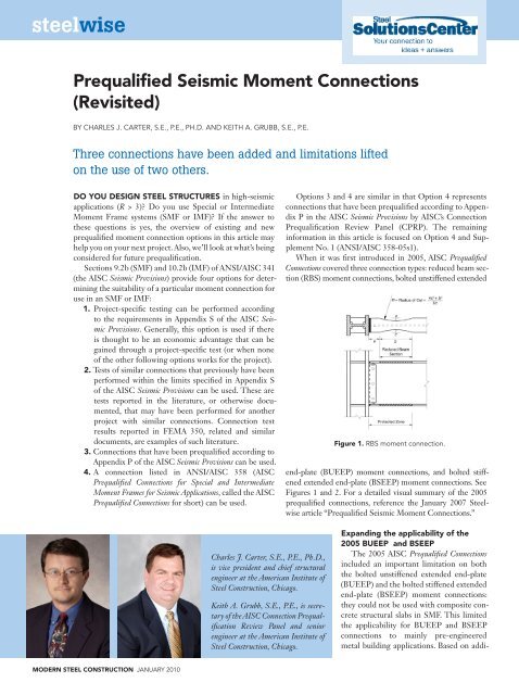
REDUCED BEAM SECTION (RBS)<br />
Options 3 and MOMENT 4 are similar CONNECTION in that Option 4 represents<br />
connections that have been prequalified according to Appen-<br />
5.1 General<br />
dix P in the In a AISC reduced beam <strong>Seismic</strong> section (RBS) Provisions moment connection by AISC’s (Figure 5.1), Connection<br />
portions<br />
of the beam flanges are selectively trimmed in the region adjacent to the beam-<br />
Prequalification to-column connection. Review Yielding Panel and hinge (CPRP). formation are The intended to remaining<br />
occur<br />
primarily within the reduced section of the beam.<br />
information in this article is focused on Option 4 and Supplement<br />
5.2 No. Systems 1 (ANSI/AISC 358-05s1).<br />
RBS connections are prequalified for use in special moment frame (SMF) and in-<br />
When it termediate was moment first frame introduced (IMF) systems in within 2005, the limits AISC of these provisions. <strong>Prequalified</strong><br />
<strong>Connections</strong> covered three connection types: reduced beam sec-<br />
5.3 Prequalification Limits<br />
tion (RBS) moment connections, bolted unstiffened extended<br />
Fig. 5.1. Reduced beam section connection.<br />
Figure 1. rBs moment connection.<br />
<strong>Prequalified</strong> <strong>Connections</strong> for Special and Intermediate Steel <strong>Moment</strong> Frames for <strong>Seismic</strong> Applications<br />
AMERICAN INSTITUTE OF STEEL CONSTRUCTION, INC.<br />
end-plate (BUEEP) moment connections, and bolted stiffened<br />
extended end-plate (BSEEP) moment connections. See<br />
Figures 1 and 2. For a detailed visual summary of the 2005<br />
prequalified connections, reference the January 2007 Steelwise<br />
article “<strong>Prequalified</strong> <strong>Seismic</strong> <strong>Moment</strong> <strong>Connections</strong>.”<br />
Expanding the applicability of the<br />
2005 BUEEP and BSEEP<br />
The 2005 AISC <strong>Prequalified</strong> <strong>Connections</strong><br />
included an important limitation on both<br />
the bolted unstiffened extended end-plate<br />
(BUEEP) and the bolted stiffened extended<br />
end-plate (BSEEP) moment connections:<br />
they could not be used with composite concrete<br />
structural slabs in SMF. This limited<br />
the applicability for BUEEP and BSEEP<br />
connections to mainly pre-engineered<br />
metal building applications. Based on addi-
tional testing, the CPRP was able to remove this limitation<br />
in Supplement No. 1. BUEEP and BSEEP moment<br />
connections can now be used with composite slabs in SMF.<br />
In the connection, the beam is welded to an extended<br />
end-plate, which is then bolted to the column in one of<br />
three specified configurations as provided in AISC 358-05.<br />
Supplement No. 1 thus allows moment end plates to be<br />
6.2– 23<br />
considered for use in the majority of buildings.<br />
Also thanks to Supplement No. 1 to ANSI/AISC 358-05,<br />
CHAPTER 6<br />
three more connection types now are prequalified; Supplement<br />
BOLTED No. 1 UNSTIFFENED adds prequalified AND details STIFFENED for bolted EXTENDED flange plate<br />
(BFP) moment END-PLATE connections, MOMENT welded CONNECTIONS<br />
unreinforced flangewelded<br />
web (WUF-W) moment connections, and Kaiser<br />
6.1 General<br />
bolted bracket (KBB) moment connections. See Figures 3,<br />
Bolted end-plate connections are made by welding the beam to an end-plate and<br />
4, and 5. bolting The the latter end-plate connection to a column flange. is a proprietary The three end-plate connection<br />
configurations<br />
shown in Figure 6.1 are covered in this section and are prequalified under the<br />
detail that uses cast steel brackets.<br />
AISC_<strong>Prequalified</strong>_1 1/27/07 7:02 AM Page 23<br />
AISC <strong>Seismic</strong> Provisions within the limitations of this Standard.<br />
The behavior of this type of connection can be controlled by a number of different<br />
BFP <strong>Moment</strong> limit states <strong>Connections</strong><br />
including flexural yielding of the beam section, flexural yielding of<br />
the end-plates, yielding of the column panel zone, tension failure of the end-<br />
As shown in Figure 3, bolted flange plate (BFP) moment<br />
plate bolts, shear failure of the end-plate bolts, or failure of various welded con-<br />
connections nections. use The intent plates of the welded design criteria to provided column here is flanges to provide sufficient with<br />
strength in the elements of the connections to ensure that the inelastic deforma-<br />
complete-joint-penetration (CJP) groove welds and bolted<br />
tion of the connection is achieved by beam yielding.<br />
to beam flanges with high-strength bolts. The beam web is<br />
6.2 connected Systems to the column flange using a bolted single-plate<br />
Extended end-plate connections are prequalified for use in special moment frame<br />
shear connection with bolts in short-slotted holes. Inelas-<br />
(SMF) and intermediate moment frame (IMF) systems.<br />
tic rotation is intended to occur in the beam in the region<br />
Exception: SMF systems in direct contact with concrete structural slabs are not<br />
near the prequalified. end of the flange plates.<br />
(a) Four-Bolt<br />
Unstiffened, 4E<br />
(b) Four-Bolt<br />
Stiffened, 4ES<br />
(c) Eight-Bolt<br />
Stiffened, 8ES<br />
Figure 2. BueeP Fig. 6.1. Extended and BseeP end-plate moment configurations. connections.<br />
Protected Zone = Sh + d<br />
<strong>Prequalified</strong> <strong>Connections</strong> for Special and Intermediate Steel <strong>Moment</strong> Frames for <strong>Seismic</strong> Applications<br />
AMERICAN INSTITUTE OF STEEL CONSTRUCTION, INC.<br />
Continuity and Doubler<br />
Plates as Required<br />
Fig. 7.1 Bolted flange plate moment connection.<br />
Figure 3. BFP moment connection.<br />
Shims, if required<br />
Single-Plate Web<br />
Connection<br />
Shims, if required<br />
The flange plates and web shear plate are shop welded<br />
to the column flange and field bolted to the beam flanges<br />
and web, respectively. ASTM A490 or A490M bolts with<br />
threads excluded from the shear plane are used for the<br />
beam flange connections because the higher shear strength<br />
of the A490 or A490M bolts reduces the number of bolts<br />
required and reduces the length of the flange plate. The<br />
shorter flange plates that are therefore possible reduce the<br />
seismic inelastic deformation demands on the connection<br />
and simplify the balance of the resistances required for different<br />
failure modes in the design procedure. Flange plate<br />
connections with A325 or A325M bolts may be possible, but<br />
will be significantly more difficult to accomplish because<br />
of the reduced bolt strength, greater number of bolts, and<br />
longer flange plates required. As a result, the connection is<br />
not prequalified for use with A325 or A325M bolts.<br />
The fundamental seismic behaviors expected with BFP<br />
moment connections include:<br />
1. initial yielding of the beam at the last bolt away from<br />
the face of the column;<br />
2. slip of the flange plate bolts, which occurs at similar<br />
resistance levels to the initial yielding in the beam<br />
flange, but the slip does not contribute greatly to the<br />
total deformation capacity of the connection;<br />
3. secondary yielding in the column panel zone, which<br />
occurs as the expected moment capacity and as strain<br />
hardening of beam hinge occurs; and,<br />
4. limited yielding of the flange plate, which may occur<br />
at the maximum deformations.<br />
This sequence of yielding has resulted in very large<br />
inelastic deformation capacity for BFP moment connections,<br />
but the design procedure is somewhat more complex<br />
than some other prequalified connections.<br />
WUF-W <strong>Moment</strong> <strong>Connections</strong><br />
As shown in Figure 4, welded unreinforced flangewelded<br />
web (WUF-W) moment connections utilize CJP<br />
groove welds to connect the beam flanges to the column<br />
Protected Zone<br />
d<br />
Figure 4. WuF-W moment connection.<br />
Fig. 8.1. WUF-W moment connection.<br />
d<br />
january 2010 MODERN STEEL CONSTRUCTION
flanges. The beam web is bolted to a single-plate shear<br />
connection for erection. Subsequently, this plate is used as<br />
a backing bar for a CJP groove weld between the beam<br />
web and the column flange. A fillet weld also is used as<br />
shown in Figure 4. Inelastic rotation is intended to occur<br />
in the beam in the region adjacent to the face of the column.<br />
Connection fracture is controlled through special<br />
detailing requirements associated with the welds joining<br />
the beam flanges to the column flange, the welds joining<br />
the beam web to the column flange, and the shape and finish<br />
of the weld access holes.<br />
The welded unreinforced flange-welded web (WUF-W)<br />
moment connection is an all-welded moment connection,<br />
wherein the beam flanges and the beam web are welded<br />
directly to the column flange. A number of welded<br />
moment connections that came into use after the 1994<br />
Northridge Earthquake, such as the reduced beam section<br />
and connections provided with beam flange reinforcement,<br />
were designed to move the plastic hinge away from the<br />
face of the column. In the case of the WUF-W moment<br />
connection, the plastic hinge is not moved away 6.1–40 from<br />
the face of the column. Rather, the WUF-W moment<br />
connection employs design and detailing features that<br />
are intended to permit the connection to achieve SMF<br />
performance criteria without fracture.<br />
The beam flanges are welded to the column flange<br />
using CJP groove welds that meet the requirements of<br />
demand critical welds in the AISC <strong>Seismic</strong> Provisions, along<br />
with specific requirements for treatment of backing and<br />
weld tabs and welding quality control and quality assurance<br />
requirements.<br />
The beam web is welded directly to the column flange<br />
using a CJP groove weld that extends the full-depth of<br />
Figure 5. KBB moment connections.<br />
MODERN STEEL CONSTRUCTION january 2010<br />
the web (that is, from weld access hole to weld access<br />
hole). This is supplemented by a single-plate connection,<br />
wherein a single plate is welded to the column flange and<br />
is then fillet welded to the beam web. Consequently, the<br />
beam web is attached to the column flange with both a<br />
CJP groove weld and a welded single-plate connection.<br />
The single-plate connection adds stiffness to the beam web<br />
connection, drawing stress toward the web connection and<br />
away from the beam flange to column connections. The<br />
single plate also serves as backing for the CJP groove weld<br />
connecting the beam web to the column flange.<br />
Instead of using a conventional weld access hole detail<br />
as specified in Section J1.6 of ANSI/AISC 360 (the AISC<br />
Specification), the WUF-W moment connection employs<br />
a special seismic weld access hole with requirements on<br />
size, shape, and finish that reduce stress concentrations in<br />
the region around the access hole (see Figure 6, which is a<br />
reprint of Figure 11-1 in the AISC <strong>Seismic</strong> Provisions).<br />
KBB <strong>Moment</strong> <strong>Connections</strong><br />
As shown PART in I – ORDINARY Figure MOMENT 5, Kaiser FRAMES bolted bracket (KBB) [Sect. 11.<br />
moment connections use a cast high-strength steel bracket<br />
groove welds and single-sided fillet welds shall not be used to resist<br />
fastened to each beam flange and bolted to the column flange.<br />
tensile forces in the connections.<br />
The bracket attachment to the beam flange is permitted to<br />
(4) For FR moment connections, the required shear strength, Vu or Va, as appro-<br />
be priate, either of welded the connection or bolted, shall be and determined multiple using bracket the following configura- quantity<br />
tions for the are earthquake available load for effect each E: of these cases proportioned to<br />
develop the probable maximum E = 2[1.1R moment capacity of the<br />
yMp]/Lh (11-1)<br />
connected beam. Inelastic rotation is intended to occur in<br />
Where this E is used in ASD load combinations that are additive with other<br />
the transient beam in loads the and region that are near based the on end SEI/ASCE of the 7, brackets. the 0.75 combination<br />
factor KBB for moment transient loads connections shall not be applied are designed to E. to eliminate<br />
field Alternatively, welding a and lesser value facilitate of Vu or frame Va is permitted erection. if justified Depending by analysis.<br />
on The fabrication required shear preference, strength need the not exceed brackets the shear can resulting be either from fillet the ap-<br />
welded plication or of bolted appropriate to the load combinations beam. The in proprietary the applicable building design code of<br />
using the amplified seismic load.<br />
Notes: 1. Bevel as required for selected groove weld.<br />
2. Larger of tbf or 2 in. (13 mm) (plus 2 t bf, or minus 4 tbf)<br />
3. w t bf to tbf, w in. (19 mm) minimum (± 4 in.) (± 6 mm)<br />
4. a in. (10 mm) minimum radius (plus not limited, minus 0)<br />
5. 3 t bf (± 2 in.) (±13 mm)<br />
6. See FEMA-353, “Recommended Specifications and Quality Assurance Guidelines<br />
for Steel <strong>Moment</strong>-Frame Construction for <strong>Seismic</strong> Applications,” for fabrication details<br />
including cutting methods and smoothness requirements.<br />
Tolerances shall not accumulate to the extent that the angle of the access hole cut to the flange<br />
surface exceeds 25°.<br />
Fig. 11–1. Weld access hole detail (from FEMA 350,<br />
“Recommended <strong>Seismic</strong> Figure Design 6. special Criteria for seismic New Steel weld <strong>Moment</strong>-Frame access hole Buildings”).<br />
for WuF-W moment connection.<br />
<strong>Seismic</strong> Provisions for Structural Steel Buildings, March 9, 2005, incl. Supplement No. 1<br />
AMERICAN INSTITUTE OF STEEL CONSTRUCTION, INC.
the brackets is protected under U.S. patent<br />
number 6,073,405 held by Steel Cast <strong>Connections</strong><br />
LLC. Additional information can<br />
be found at www.steelcastconnections.<br />
com. The connection is not prequalified<br />
when brackets of an unlicensed design and/<br />
or manufacture are used.<br />
Future Work<br />
The AISC CPRP continues to work on<br />
the prequalification of additional moment<br />
connection types for high-seismic applications.<br />
Several connection types currently<br />
are under consideration:<br />
1. The ConXtech® ConXL moment<br />
connection, shown in Figure 7, is<br />
currently being tested as a bi-axial<br />
moment connection using the qualifying<br />
cyclic loading sequence in the<br />
AISC <strong>Seismic</strong> Provisions in the primary<br />
framing direction, while a constant<br />
moment is applied across the<br />
connection in the orthogonal direction.<br />
The constant moment is equal<br />
to the probable maximum moment,<br />
M pr, at the plastic hinges of the test<br />
specimen beams, which means the<br />
assembly will be subjected to at least<br />
100% M pr about both axes, simultaneously.<br />
This proprietary connection<br />
is protected under several U.S. and<br />
international patents held by ConXtech,<br />
Inc.<br />
2. Bolted double tee moment connections.<br />
3. Welded double tee moment connections.<br />
Anyone with an interest in submitting<br />
test results for existing and new moment<br />
connections for consideration for prequalification<br />
by AISC’s CPRP should contact<br />
the Committee Secretary, Keith Grubb, at<br />
grubb@aisc.org.<br />
Summary<br />
ANSI/AISC 358-05s1 (Supplement<br />
No. 1 to ANSI AISC 358 -05) now<br />
provides a greater variety of prequalified<br />
moment connection options for special<br />
moment frames (SMF) and intermediate<br />
moment frames (IMF). It is available for<br />
free download along with ANSI/AISC<br />
358-05, ANSI/AISC341-05, and ANSI/<br />
AISC 360-05 at www.aisc.org/epubs.<br />
With more options available, AISC 358-<br />
05s1 likely will help make your next<br />
project easier and more economical.<br />
AISC<br />
Web-Based<br />
Course<br />
Figure 7. ConXl tM moment connections.<br />
Membership in AISC or NISD will<br />
result in a fee reduction of 25%<br />
or 10%, respectively. Members<br />
of both organizations will receive<br />
a total fee reduction of 35%.<br />
What’s the next-best thing to an internship<br />
with an experienced detailer? An online<br />
detailing course—developed by Dowco<br />
Consultants and endorsed by AISC—is<br />
an invaluable tool for detailing firms and<br />
fabricators alike. The program, which takes<br />
approximately 400 hours to complete,<br />
includes lessons on contract documents and<br />
the detailing process, common connection<br />
details, basic detailing conventions, project<br />
set-up and control, erection drawings,<br />
shop drawings and bills of materials, and<br />
detailing quality control and assurance.<br />
For complete information, visit<br />
www.structuraldetailertraining.com<br />
Entry-Level Detailer Training<br />
Dowco Consultants, Ltd.<br />
American Institute of<br />
Steel Construction<br />
There’s always a solution in steel.<br />
january 2010 MODERN STEEL CONSTRUCTION