

Insulation Tester Digital - HHMI60 Manual - Omega Engineering
Insulation Tester Digital - HHMI60 Manual - Omega Engineering
Insulation Tester Digital - HHMI60 Manual - Omega Engineering

Create successful ePaper yourself
Turn your PDF publications into a flip-book with our unique Google optimized e-Paper software.
250V/500V/1000V<br />
User’s Guide<br />
Shop online at<br />
omega.com<br />
e-mail: info@omega.com<br />
For latest product manuals:<br />
omegamanual.info<br />
®<br />
CAT.¢ó 50V<br />
MADE IN CHINA<br />
PRESS AND TURN-FOR<br />
CONTINUOUS<br />
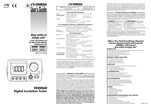
<strong>HHMI60</strong><br />
<strong>Digital</strong> <strong>Insulation</strong> <strong>Tester</strong><br />
®<br />
OMEGAnet ® Online Service Internet e-mail<br />
omega.com info@omega.com<br />
U.S.A.:<br />
Servicing North America:<br />
<strong>Omega</strong> <strong>Engineering</strong>, Inc., One <strong>Omega</strong> Drive, P.O. Box 4047<br />
ISO 9001 Certified Stamford, CT 06907-0047<br />
Toll-Free: 1-800-826-6342 Tel: (203) 359-1660<br />
FAX: (203) 359-7700 e-mail: info@omega.com<br />
Canada: 976 Bergar<br />
Laval (Quebec), H7L 5A1 Canada<br />
Toll-Free: 1-800-826-6342 TEL: (514) 856-6928<br />
FAX: (514) 856-6886 e-mail: info@omega.ca<br />
For immediate technical or application assistance:<br />
U.S.A. and Canada: Sales Service: 1-800-826-6342/1-800-TC-OMEGA ®<br />
Customer Service: 1-800-622-2378/1-800-622-BEST ®<br />
<strong>Engineering</strong> Service: 1-800-872-9436/1-800-USA-WHEN ®<br />
Mexico/ En Español: 001 (203) 359-7803 FAX: 001 (203) 359-7807<br />
Latin America info@omega.com.mx e-mail: espanol@omega.com<br />
Servicing Europe:<br />
Benelux: Managed by the United Kingdom Office<br />
Toll-Free: 0800 099 3344 TEL: +31 20 347 21 21<br />
Czech Republic:<br />
FAX: +31 20 643 46 43 e-mail: sales@omegaeng.nl<br />
Frystatska 184<br />
733 01 Karviná, Czech Republic<br />
Toll-Free: 0800-1-66342 TEL: +420-59-6311899<br />
France:<br />
FAX: +420-59-6311114e-mail: info@omegashop.cz<br />
Managed by the United Kingdom Office<br />
Toll-Free: 0800 466 342 TEL: +33 (0) 161 37 29 00<br />
FAX: +33 (0) 130 57 54 27 e-mail: sales@omega.fr<br />
Germany/Austria: Daimlerstrasse 26<br />
D-75392 Deckenpfronn, Germany<br />
Toll-Free: 0800 6397678 TEL: +49 (0) 7056 9398-0<br />
FAX: +49 (0) 7056 9398-29 e-mail: info@omega.de<br />
United Kingdom: OMEGA <strong>Engineering</strong> Ltd.<br />
ISO 9001 Certified One <strong>Omega</strong> Drive, River Bend Technology Centre, Northbank<br />
Irlam, Manchester M44 5BD United Kingdom<br />
Toll-Free: 0800-488-488 TEL: +44 (0) 161 777-6611<br />
FAX: +44 (0) 161 777-6622 e-mail: sales@omega.co.uk<br />
It is the policy of OMEGA <strong>Engineering</strong>, Inc. to comply with all worldwide safety and EMC/EMI<br />
regulations that apply. OMEGA is constantly pursuing certification of its products to the<br />
European New Approach Directives. OMEGA will add the CE mark to every appropriate device<br />
upon certification. The information contained in this document is believed to be correct,<br />
but OMEGA accepts no liability for any errors it contains, and reserves the right to alter<br />
specifications without notice. WARNING: These products are not designed for use in, and<br />
should not be used for, human applications.<br />
WARRANTY/ DISCLAIMER<br />
OMEGA ENGINEERING, INC. warrants this unit to be free of defects in materials and<br />
workmanship for a period of 13 months from date of purchase. OMEGA’s Warranty adds<br />
an additional one (1) month grace period to the normal one (1) year product warranty<br />
to cover handling and shipping time. This ensures that OMEGA’s customers receive<br />
maximum coverage on each product.<br />
If the unit malfunctions, it must be returned to the factory for evaluation. OMEGA’s<br />
Customer Service Department will issue an Authorized Return (AR) number immediately<br />
upon phone or written request. Upon examination by OMEGA, if the unit is found to be<br />
defective, it will be repaired or replaced at no charge. OMEGA’s WARRANTY does not<br />
apply to defects resulting from any action of the purchaser, including but not limited to<br />
mishandling, improper interfacing, operation outside of design limits, improper repair, or<br />
unauthorized modification. This WARRANTY is VOID if the unit shows evidence of having<br />
been tampered with or shows evidence of having been damaged as a result of excessive<br />
corrosion; or current, heat, moisture or vibration; improper specification; misapplication;<br />
misuse or other operating conditions outside of OMEGA’s control. Components in which<br />
wear is not warranted, include but are not limited to contact points, fuses, and triacs.<br />
OMEGA is pleased to offer suggestions on the use of its various products.<br />
However, OMEGA neither assumes responsibility for any omissions or errors nor<br />
assumes liability for any damages that result from the use of its products in<br />
accordance with information provided by OMEGA, either verbal or written.<br />
OMEGA warrants only that the parts manufactured by the company will be as<br />
specified and free of defects. OMEGA MAKES NO OTHER WARRANTIES OR<br />
REPRESENTATIONS OF ANY KIND WHATSOEVER, EXPRESSED OR IMPLIED,<br />
EXCEPT THAT OF TITLE, AND ALL IMPLIED WARRANTIES INCLUDING ANY<br />
WARRANTY OF MERCHANTABILITY AND FITNESS FOR A PARTICULAR<br />
PURPOSE ARE HEREBY DISCLAIMED. LIMITATION OF LIABILITY: The remedies<br />
of purchaser set forth herein are exclusive, and the total liability of OMEGA with<br />
respect to this order, whether based on contract, warranty, negligence,<br />
indemnification, strict liability or otherwise, shall not exceed the purchase price<br />
of the component upon which liability is based. In no event shall OMEGA be<br />
liable for consequential, incidental or special damages.<br />
®<br />
CONDITIONS: Equipment sold by OMEGA is not intended to be used, nor shall it be used:<br />
(1) as a “Basic Component” under 10 CFR 21 (NRC), used in or with any nuclear<br />
installation or activity; or (2) in medical applications or used on humans. Should any<br />
Product(s) be used in or with any nuclear installation or activity, medical application, used<br />
on humans, or misused in any way, OMEGA assumes no responsibility as set forth in our<br />
basic WARRANTY/ DISCLAIMER language, and, additionally, purchaser will indemnify<br />
OMEGA and hold OMEGA harmless from any liability or damage whatsoever arising out<br />
of the use of the Product(s) in such a manner.<br />
RETURN REQUESTS / INQUIRIES<br />
Direct all warranty and repair requests/inquiries to the OMEGA Customer Service<br />
Department. BEFORE RETURNING ANY PRODUCT(S) TO OMEGA, PURCHASER MUST<br />
OBTAIN AN AUTHORIZED RETURN (AR) NUMBER FROM OMEGA’S CUSTOMER<br />
SERVICE DEPARTMENT (IN ORDER TO AVOID PROCESSING DELAYS). The assigned AR<br />
number should then be marked on the outside of the return package and on any<br />
correspondence. The purchaser is responsible for shipping charges, freight, insurance<br />
and proper packaging to prevent breakage in transit.<br />
FOR WARRANTY RETURNS, please<br />
have the following information available<br />
BEFORE contacting OMEGA:<br />
1. Purchase Order number under which<br />
the product was PURCHASED,<br />
2. Model and serial number of the product<br />
under warranty, and<br />
3. Repair instructions and/or specific<br />
problems relative to the product.<br />
FOR NON-WARRANTY REPAIRS, consult<br />
OMEGA for current repair charges. Have the<br />
following information available BEFORE<br />
contacting OMEGA:<br />
1. Purchase Order number to cover the COST<br />
of the repair,<br />
2. Model and serial number of the product, and<br />
3. Repair instructions and/or specific problems<br />
relative to the product.<br />
OMEGA’s policy is to make running changes, not model changes, whenever an<br />
improvement is possible. This affords our customers the latest in technology and<br />
engineering. OMEGA is a registered trademark of OMEGA ENGINEERING, INC.<br />
© Copyright 2012 OMEGA ENGINEERING, INC. All rights reserved. This document may<br />
not be copied, photocopied, reproduced, translated, or reduced to any electronic medium<br />
or machine-readable form, in whole or in part, without the prior written consent of<br />
OMEGA ENGINEERING, INC.<br />
Where Do I Find Everything I Need for<br />
Process Measurement and Control?<br />
OMEGA…Of Course!<br />
Shop online at omega.com sm<br />
TEMPERATURE<br />
Thermocouple, RTD & Thermistor Probes, Connectors, Panels & Assy.<br />
Wire: Thermocouple, RTD & Thermistor<br />
Calibrators & Ice Point References<br />
Recorders, Controllers & Process Monitors<br />
Infrared Pyrometers<br />
PRESSURE, STRAIN AND FORCE<br />
Transducers & Strain Gages<br />
Load Cells & Pressure Gages<br />
Displacement Transducers<br />
Instrumentation & Accessories<br />
FLOW/LEVEL<br />
Rotameters, Gas Mass Flowmeters & Flow Computers<br />
Air Velocity Indicators<br />
Turbine/Paddlewheel Systems<br />
Totalizers & Batch Controllers<br />
pH/CONDUCTIVITY<br />
pH Electrodes, <strong>Tester</strong>s & Accessories<br />
Benchtop/Laboratory Meters<br />
Controllers, Calibrators, Simulators & Pumps<br />
Industrial pH & Conductivity Equipment<br />
DATA ACQUISITION<br />
Data Acquisition & <strong>Engineering</strong> Software<br />
Communications-Based Acquisition Systems<br />
Plug-in Cards for Apple, IBM & Compatibles<br />
Data Logging Systems<br />
Recorders, Printers & Plotters<br />
HEATERS<br />
Heating Cable<br />
Cartridge & Strip Heaters<br />
Immersion & Band Heaters<br />
Flexible Heaters<br />
Laboratory Heaters<br />
ENVIRONMENTAL MONITORING AND CONTROL<br />
Metering & Control Instrumentation<br />
Refractometers<br />
Pumps & Tubing<br />
Air, Soil & Water Monitors<br />
Industrial Water & Wastewater Treatment<br />
pH, Conductivity & Dissolved Oxygen Instruments M5088/0212
DIGITAL INSULATION TESTER<br />
OPERATION MANUAL<br />
Contents<br />
1.General Description ............................................................1<br />
2.Panel Descriptions .............................................................1<br />
3.Technical Specifications .....................................................2<br />
4.Operation Instructions ........................................................4<br />
5.<strong>Insulation</strong> Resistance Measurement ..................................4<br />
6. Resistance and Continuity Measurement ..........................5<br />
7.DCV Measurement .............................................................6<br />
8.ACV Measurement .............................................................7<br />
9.Data Hold and Backlit Display ............................................7<br />
10.Safety Precautions and Maintenance ...............................8<br />
11.Battery and Fuse Replacement ........................................ 9<br />
12.Trouble Shooting ............................................................10<br />
13.Standard Accessories ....................................................10<br />
1. General Description<br />
This instrument is a digital insulation tester which adopts<br />
DC voltage converter of low consumption, high converter<br />
ratio, and inductance type energy storage to convert the<br />
voltage of 9V DC into 250V/500V/1000V DC. With digital<br />
bridge, the instrument can test insulation and its main<br />
features include easy to operate, wide test range, highly<br />
stable performance, backlit LCD display, data hold and auto<br />
power off. Using a shoulder strap, it can be used by both<br />
hands. It is an ideal instrument that can be used in testing<br />
insulation of electric machines, cables, electronic<br />
equipments, electric facilities, etc.<br />
2. Panel Description<br />
250V/500V/1000V<br />
1. Power switch/function switch: power ON/OFF the<br />
instrument and selects functions. To save power, please<br />
turn the switch to “OFF” when it isn’t in use.<br />
2. LCD display: displays testing results and unit symbols<br />
CAT.¢ó 50V<br />
PRESS AND TURN-FOR<br />
CONTINUOUS<br />
3. E: Input terminal for the measuring object.<br />
4. L: Terminal for connecting to the GND of the measuring<br />
object<br />
5. G: Protection terminal. When the measuring object is<br />
required to add the protection loop to eliminate the leakage<br />
effect, connect the electrode wire of the protection loop to<br />
“G” terminal. It is also the negative input terminal for<br />
measuring voltage, resistance and continuity.<br />
6. Voltage measurement, resistance measurement (
3) To ensure measurement accuracy, warm up the<br />
instrument for at least 10 seconds before operation.<br />
5. <strong>Insulation</strong> resistance measurement:<br />
1) According to the testing request, tune the function switch<br />
to a suitable function.<br />
2) Connect the electrode of the measuring object to the<br />
relative terminals of the tester.<br />
3) When testing a cable, connect ‘G’ terminal to the<br />
protection loop.<br />
4) Press “TEST” button to start the measurement. Read the<br />
data after the display stabilized. For continuous<br />
measurement, turn the function switch to the right and<br />
lock it. Turn the function switch to the left can cancel the<br />
continuous measurement. When press the “TEST”<br />
button, the high voltage indicator turns red, and the high<br />
voltage symbol will be displayed on the LCD. At the<br />
same time, the beeper alarms with “tick-tick” sound. If<br />
the resistance of the measuring insulation is 5% less<br />
than the selected range or if there is a short circuit, the<br />
beeper alarms with a long sound “tick……”<br />
5) Connect the red lead “E” to the measuring object, and<br />
black lead “L” to the EARTH. The line of Lead “E”<br />
is required to be hung in the air.<br />
6) If the LCD displays “1”, it indicates over range<br />
operation. Please choose a higher range to get reading.<br />
CAUTION!<br />
1) When press the “TEST” button, output terminal“E”<br />
will have high voltage output. Be careful, and avoid<br />
electric shock.<br />
2) Before testing, make sure the voltage range is correct,<br />
and the LCD display is in accordance with selected<br />
voltage.<br />
3) During MΩ measurement, the environmental interference<br />
or the instability of insulation material may cause<br />
unstable readings. In this case, connect terminal “G” to<br />
the end shield of the measuring object to get stable<br />
readings.<br />
6. Resistance and Continuity Measurement:<br />
1. Tune the function switch to range 2000Ω.<br />
2. Connect the red lead to “V/Ω” input terminal and black<br />
lead to “G” input terminal.<br />
3. Connect the test leads across the tested circuit. The<br />
LCD will display the data.<br />
4. If the tested resistance is less than approx.50Ω, the<br />
beeper alarms<br />
CAUTION!<br />
1. If the tested resistance is over 2kΩ or there is an open<br />
circuit, the LCD displays “1”.<br />
2. When testing a live resistor, to ensure safety, do not<br />
proceed testing until the tested circuit is completely<br />
powered off and all capacitors are fully discharged.<br />
3. If testing results have considerable errors, it may be<br />
caused by other live components in the same circuit or<br />
by electric potential on the two ends of the resistor.<br />
4. Do not input voltage to the resistance range!<br />
7. DCV Measurement:<br />
1. Tune the function switch to DC 1000V range.<br />
2. Connect the red lead to “V/Ω” input terminal and black<br />
lead to “G” input terminal.<br />
3. Connect the test leads across the tested circuit. The<br />
LCD will display the voltage and polarity of the red lead<br />
touched point.<br />
CAUTION!<br />
1. If there is residue number before measurement, it is<br />
normal and will not affect the measurement. If the LCD<br />
displays “1” during measurement, it indicates over<br />
range operation.<br />
2. The input voltage must not be over DC 1000V. Voltage<br />
over DC 1000V will cause damage to the instrument<br />
3<br />
circuit.<br />
3. During high voltage circuit measurement, do not touch<br />
the high voltage. It’s dangerous to get electric shock!<br />
8. ACV Measurement:<br />
1. Tune the function switch to AC 750V range.<br />
2. Connect the red lead to “V/Ω” input terminal and black<br />
lead to “G” input terminal.<br />
3. Connect the test leads across the tested circuit. The<br />
LCD will display the voltage and polarity of the red lead<br />
touched point.<br />
CAUTION!<br />
1. If there is residue numbers before measurement, it is<br />
normal and will not affect the measurement. If the LCD<br />
displays “1” during measurement, it indicates over<br />
range operation.<br />
2. The input voltage must not be over AC 750V. Voltage<br />
over AC 750V will cause damage to the instrument<br />
circuit.<br />
3. During high voltage circuit measurement, do not touch<br />
the high voltage. It’s dangerous to get electric shock!<br />
9. Data Hold and Backlit Display<br />
Data Hold:<br />
Press the “HOLD” button, the current data will be held on<br />
the LCD. Press the “HOLD” button again to cancel data<br />
hold.<br />
NOTE: There is no data hold function during insulation<br />
resistance measurement.<br />
Backlit Display:<br />
Pressing “*” button, the LCD backlight turns on. Pressing “*”<br />
button again, the LCD backlight turns off.<br />
10. Safety Precautions and Maintenance<br />
The tester is a precise instrument. User is not allowed to<br />
apply any modification to the instrument circuit.<br />
CAUTION!<br />
1. To ensure safety, the measuring object must be<br />
completely shut off from power supply and must be
testified by short circuit to be fully discharged and<br />
doesn’t have any electrical hazard.<br />
2. Do not input voltage over DC 1000V or AC 750V.<br />
3. Don’t apply voltage measurement in the Ω range.<br />
4. Do not apply any measurement until the instrument's<br />
batteries are well installed or until the rear cover is<br />
well loaded.<br />
5. Before replacing battery or replacing fuse, remove all<br />
test leads from the measuring object and turn off the<br />
power switch.<br />
6. Keep the instrument away from water and dust. Do not<br />
fall or throw the instrument on ground.<br />
7. Keep the instrument away from high temperature, high<br />
humidity, flammable, explosive and strong magnetic<br />
environment.<br />
8. Use a piece of soft cloth with mild detergent and water to<br />
clean the instrument. Do not use any abrasives or<br />
strong solvent.<br />
9. If you don’t use it for a long time, take out the batteries<br />
from the instrument to avoid battery leakage<br />
damaging the instrument.<br />
10. When you use 9V battery, if the LCD displays low<br />
battery symbol “ ”, replace battery.<br />
11. Battery and Fuse Replacement<br />
Battery Replacement<br />
1) Use a screw driver to open the battery door’s screws,<br />
and take off the battery door.<br />
2) Take off the battery and replace with a new one. To<br />
ensure long time battery power supply, it is<br />
recommended to use alkaline batteries.<br />
3) Close the battery door and tighten the screws.<br />
Fuse replacement<br />
The instrument uses a 100mA/60V resettable fuse.<br />
In case of replacement, please use the fuse of same<br />
specification, and follow instructions as below:<br />
1) Tune the function switch to “OFF” position.<br />
2) Use a screw driver to loosen the screws on the bottom,<br />
and take off the bottom cover.<br />
3) Remove the screws on the PCB, and take off the PCB.<br />
4) Locate the resettable fuse on the PCB, which is marked<br />
with “FUSE”. Use a soldering iron to take off the fuse<br />
and replace it with a new one of the same spec.<br />
12. Trouble Shooting<br />
If the instrument dose not work properly, the following selfcheck<br />
steps will help to solve general problems. If the fault still<br />
exists, please contact the maintenance or local distributor.<br />
Fault Solution<br />
• Power off - please turn on<br />
No display<br />
the power<br />
• Replace the batteries<br />
symbol appearance • Replace the batteries<br />
Error value • Replace the batteries<br />
13. Standard Accessories<br />
1. 10A test lead x1 pair<br />
2. AA battery (1.5V) x6pcs<br />
3. Operation manual x1pcs<br />
4. Shoulder strap x1pcs<br />
5. Crocodile clip x1 pair<br />
The operation manual is subject to change without prior<br />
notice. The contents in this operation manual are<br />
considered to be correct.<br />
If user finds out any mistakes or omissions, please contact<br />
the manufacturer.<br />
The manufacturer will not be responsible for any accident<br />
or damage caused by improper operation.<br />
4


