Gilbarco/Epex Dual-purpose Self-serve Driveway Flowmeter Model ...
Gilbarco/Epex Dual-purpose Self-serve Driveway Flowmeter Model ...
Gilbarco/Epex Dual-purpose Self-serve Driveway Flowmeter Model ...

Create successful ePaper yourself
Turn your PDF publications into a flip-book with our unique Google optimized e-Paper software.
National Standards csmmissi~<br />
C/- CSIRO NATIONAL STANDARDS LABORATORY UNWERSITY mowm.<br />
CITY ROAD, CHIPPENDALE. N S W 20X3<br />
Telephone: 660- 0566 - Telegrams & Cables: Natstancom Sydney - Teleprint: AA 20248.<br />
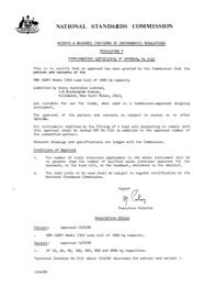
CERTIFICATE OF APPROVAL No 5/6A/9<br />
VARIATION No 1<br />
This is to certify that the following moclificatiolls of the pattern and variants of the<br />
<strong>Gilbarco</strong>/<strong>Epex</strong> <strong>Dual</strong>-<strong>purpose</strong> <strong>Self</strong>-<strong>serve</strong> <strong>Driveway</strong> <strong>Flowmeter</strong> <strong>Model</strong> T132C<br />
approved in Certificate No 5/6A/9 dated 2 April 1971<br />
submitted by Engineering Products Pty Ltd, 418-428 Burnley Street,<br />
.<br />
Burley, Victoria, 3121,<br />
have been approved under the Weights and Measures (Patterns of Instruments)<br />
Regulations as being suitable for use for trade.<br />
The approved modifications are as follows :<br />
(a) fitted with a $2.00 note acceptor;<br />
03) fitted with a $1.00 note acceptor;<br />
(c) converted to indicate in metric units in accordance with Appel~di~~ 14 of the<br />
General Specifications for Measuring Instrunlenis lo be Used for Trade.<br />
Approval \vas granted on,. 9 May 1974.<br />
This variation is described in Technical Schedule No 5/6A/9, Variation No 1, and<br />
in drawings and specifications lodged with the Commission.<br />
The approval is subject to review on or after 1 June 1979. .<br />
’ All instruments conforming to this approval shall be marked with the approval<br />
,’ number ltNSC No 5/6A/9;!.<br />
I<br />
Signed<br />
Executive Officer
Weights and Measures<br />
(National Standards)<br />
Act 1960-1966<br />
Weights and Measures<br />
(Patterns of Instruments)<br />
Regulations<br />
In respect of the pattern of<br />
COMMONWEALTH OF AUSTRALIA<br />
NATIONAL STANDARDS COMMISSION<br />
Certificate of Approval<br />
CERTlFlCATE NUMBER 5/6A/9<br />
<strong>Gilbarco</strong>/<strong>Epex</strong> <strong>Dual</strong>-<strong>purpose</strong> <strong>Self</strong>-<strong>serve</strong> Single Dispensing Pump<br />
<strong>Model</strong> T132C and Variants.<br />
Submitted by: <strong>Gilbarco</strong> Australia Ltd. ,<br />
16-34 Talavera Road,<br />
North Ryde,<br />
New South Wales. 2113.<br />
Engineering Products Pty. Ltd. ,<br />
418-428 Burnley Street,<br />
Burnley ,<br />
Victoria. 3121.<br />
Pump Conversions Pty. Ltd. ,<br />
675 High Street Road,<br />
Glen Waverley,<br />
Victoria. 3150.<br />
This is to certify that the pattern and variants of the instrument<br />
illustrated and described in this Certificate have been examined<br />
by the National Standards Commission under the provisions of<br />
the abovementioned Regulations and have been approved as<br />
being suitable for use for trade.<br />
The pattern was approved on 19th October, 1966, and further<br />
variants listed in Columns 6 and 7 of Figure 1 were approved on<br />
2/4/71 Cant’ d over
Certificate No 5/6A/9 Page 2<br />
24th November, 1966, 26th January, 1968, and 11th December, 1968.<br />
Variants listed in Columns 8 and 9 of Figure 1 were approved on 26th<br />
January, 1968, and 11th December, 1968.<br />
Approval was granted on condition that:<br />
1. all instruments made in conformity with this Certificate are<br />
appropriately marked NSC No 5/6A/9 and, where required<br />
by State legislation, with the State approval number also;<br />
and<br />
2. comply with the General Specifications for Weighing and<br />
Measuring Instruments to be Used for Trade, in respect of<br />
that part of the instrument which was not previously<br />
approved by a State.<br />
This Certificate comprises :<br />
Pages 1 to 11 dated 2nd April, 1971.<br />
Figures 5/6A/9 - 1 to 27 dated 2nd April, 1971.<br />
Pursuant to regulation 12 of the abovementioned Regulations, this<br />
Certificate is applicable in all States.<br />
Date of issue 2nd April, 1971.<br />
2/4/71<br />
Signed<br />
A person authorised by the Commission<br />
to sign Certificates under the<br />
abovementioned Regulations.
-<br />
Certificate No 5/6A/9 Page 3<br />
DESCRIPTION OF PATTERN<br />
The pattern (see Figures 2 and 3) is of a modification of the <strong>Gilbarco</strong><br />
Salesmaker Single Dispensing Pump <strong>Model</strong> 1006A approved in all<br />
States and is known as a <strong>Gilbarco</strong>/<strong>Epex</strong> <strong>Dual</strong>-<strong>purpose</strong> <strong>Self</strong>-<strong>serve</strong><br />
Single Dispensing Pump <strong>Model</strong> T132C.<br />
It comprises the <strong>Gilbarco</strong> Salesmaker Single Dispensing Pump <strong>Model</strong><br />
1006A with the computer, nozzle and nozzle hang-up removed and<br />
replaced by the components tabulated in Column 5 of Figure 1.<br />
The coin-receiving and coin-testing units are located in a separate<br />
housing, together with the control unit.<br />
The pressure bell is located in the supply tank.<br />
The hydraulic diagram is illustrated in Figure 4.<br />
The dispenser operates as a self-<strong>serve</strong> flowmeter when “automatic”<br />
mode is selected by a switch on the control unit, and by selection of<br />
“manual” mode an operator may use the dispenser as a manual<br />
flowmeter. When “automatic” mode of operation is selected the<br />
insertion of coins into the coin-receiving unit allows the dispenser<br />
to be operated by the purchaser. Inserting coins into the coin unit<br />
causes signals to be sent to the control unit, which records the value<br />
of the coins in its memory unit and indicates the value of the coins on<br />
panel lights.<br />
Lifting the nozzle from its hang-up hook starts the pump motor,<br />
allowing the purchaser to commence delivery. Signals from the<br />
computer in the dispenser are sent to the control unit, causing the<br />
memory section to count back, stopping the pump motor when the<br />
value of the delivery is equal to the value of the coins accepted by the<br />
coin unit.<br />
DESCRIPTION OF VARIANTS<br />
1. The <strong>Gilbarco</strong> Salesmaker Single Dispensing Pump 1006A with the<br />
computer, nozzle and nozzle hang-up removed and replaced by<br />
the components tabulated in Column 6 of Figure 1, make up<br />
2/4/71
Certificate No 5/6A/9 Page 4<br />
variants known as the <strong>Gilbarco</strong>/<strong>Epex</strong> <strong>Dual</strong>-<strong>purpose</strong> <strong>Self</strong>-<strong>serve</strong><br />
Single Dispensing Pump <strong>Model</strong> T132C. Each variant has the same<br />
housing and component arrangement as in the pattern.<br />
The hydraulic diagram is illustrated in Figure 4.<br />
2. The <strong>Gilbarco</strong> Salesmaker Single Dispensing Pump 1006A with the<br />
computer, nozzle and nozzle hang-up removed and replaced by the<br />
components tabulated in Column 7 of Figure 1, make up variants<br />
known as the <strong>Gilbarco</strong>/<strong>Epex</strong> <strong>Dual</strong>-<strong>purpose</strong> <strong>Self</strong>-<strong>serve</strong> Single<br />
Dispensing Pump <strong>Model</strong> T132B. Each variant has the same housing<br />
and component arrangement as in the pattern.<br />
The hydraulic diagram is illustrated in Figure 4.<br />
3. The components tabulated in Column 8 of Figure 1 replace<br />
similar components in the <strong>Epex</strong> SS/VR <strong>Self</strong>-<strong>serve</strong> Single<br />
Dispensing Pump as described in Certificate No 5/6A/19.<br />
4. The Wayne Single Dispensing Pump <strong>Model</strong> 605, as described in<br />
Certificate No 5/6A/4, with the computer, nozzle and nozzle<br />
hang-up removed and replaced by the components tabulated in<br />
Column 9 of Figure 1, make up variants known as the Wayne<br />
<strong>Self</strong>-<strong>serve</strong> Single Dispensing Pump <strong>Model</strong> 605 (see Figure 5).<br />
The coin-receiving and coin-testing units are located in a<br />
separate housing, together with the control unit.<br />
The pressure bell is located in the supply tank.<br />
DESCRIPTION OF COMPONENTS<br />
1. Computer - Veeder-Root 1611 (sterling), as described in State<br />
approvals, modified by:<br />
2/4/71<br />
(a) fitting a trip lever and cam (see Figure 7)) which causes the<br />
computer to reset to zero when the starting handle is rotated<br />
to the “off” position, that is, when the nozzle is placed on<br />
the hang-up arm ;<br />
(b) fitting projecting studs to the l-penny and lo-shilling<br />
price-indication drums on one side of the computer (see<br />
Figure 9);
Certificate No 5/6A/9 Page 5<br />
(c) fitting a bracket (see Figure 7) to the reset dashpot; and<br />
(d) fitting a bracket to the starting mechanism (see Figure 8).<br />
The projecting studs and brackets, through pushrods, operate<br />
switches and contacts in the distributor unit.<br />
2. Computer - Veeder-Root 1611 (sterling) - Component No 1,<br />
without the brackets, on the reset dashpot and starting<br />
mechanism.<br />
3. Computer - Veeder-Root 1613, as described in Certificate No<br />
5/6A/6, modified as described in Component No 1. The<br />
projecting studs are fitted to the l-cent and l-dollar<br />
price-computing drums (see Figure 9).<br />
4. Computer - Veeder-Root 1613 - Component No 3, without the<br />
brackets as described in Component No 2.<br />
5. Nozzle - <strong>Epex</strong> EP 4559 manual hose nozzle with flexible spout<br />
(see Figures 10 and 11).<br />
6. Nozzle - OPW 1ABV automatic hose nozzle (see Figures 12<br />
and 13).<br />
7. Hang-up (see Figure 14) :<br />
(a) When starting the dispenser, the starting handle causes the<br />
reset paw1 to engage in the reset cam, and a bracket<br />
operates a microswitch before the pump motor starts.<br />
(b) When stopping the dispenser, the weight of the nozzle on<br />
the starting handle depresses the starting handle,<br />
energising the reset dashpot. A trip lever and cam resets<br />
the computer to zero before the starting handle reaches its<br />
reset position.<br />
8. Solenoid valve and by-pass pipe (see Figure 15) - the solenoid<br />
valve closes when the outstanding credit, established by the value<br />
of the coins accepted by the coin tester, reaches a value<br />
equivalent to one revolution of the right-hand drum of the<br />
computer. The delivery then continues at a reduced rate of flow<br />
through the by-pass pipe.<br />
2/4/71
Certificate No 5/6A/9 Page 6<br />
9. By-pass solenoid valve - with a 1/8 inch diameter by-pass hole<br />
through the inner wall of the valve.. The valve closes as<br />
described for Co:mponent No 8 The delivery then continues at a<br />
reduced rate of flow through the by-pass hole in the valve.<br />
10. Distributor unit - <strong>Epex</strong> EP 5658 (see Figure 16), contains<br />
interlocking microswitches and pulse contacts. A pushrod, which<br />
opens and closes an electrical contact in the distributor, is<br />
lifted by a cam which rides on the external face of the right-hand<br />
drum of the computer,<br />
A projecting stud on the drum lifts the pushrod, closing the<br />
electrical contact once for each revolution of the drum. Each<br />
time the contact closes it applies a signal to the rotary switch<br />
in the control unit.<br />
A second electrical contact, which is operated by a pushrod and<br />
cam and by a projecting stud on the third drum, causes the pump<br />
motor to stop if the right-hand drum has made twenty revolutions.<br />
A microswitch operated by a bracket attached to the reset dashpot<br />
on the computer (see Figure 7) opens the circuit to the lock relay<br />
in the coin tester, preventing coins from being accepted while the<br />
computer is being reset.<br />
A second microswitch operated by a bracket on the starting-handle<br />
mechanism (see Figure 8) opens the circuit to the lock relay in the<br />
coin tester when the starting handle is in the r’on’f position, that<br />
is, when the nozzle is not on its hang-up hook.,<br />
A pressure-operated switch opens the circuit to the lock relay in<br />
the coin tester when the quantity of liquid in the supply tank has<br />
reached a preset low level, to prevent coins from being inserted<br />
when there is insufficient liquid to make a 20-shilling delivery.<br />
11. Distributor unit - <strong>Epex</strong> EP 5545, similar to Component No 10, the<br />
significant difference being the microswitch operated by a bracket<br />
attached to the reset dashpot is operated directly by contact with<br />
the reset dashpot, and the second microswitch operated by a<br />
bracket on the starting mechanism is operated directly by contact<br />
with the starting mechanism.<br />
12. Coin-receiving unit (2-shilling) - <strong>Epex</strong> (see Figure 17), registers<br />
2/4/7 1<br />
--
Certificate No 5/6A/9 Page 7<br />
13.<br />
14.<br />
15.<br />
2/4/71<br />
the value of 2-shilling coins accepted by the coin tester. Lights<br />
behind ten circular cut-outs, each cut-out being marked successively<br />
with a monetary value from 2-shillings to 20-shillings, light in<br />
accordance with the value of coins accepted by the coin tester.<br />
The lights are energised by contacts on a rotary switch in the<br />
control unit. A dimensioned slot, through which coins are inserted<br />
into the coin tester, prevents bent or misshapen coins from being<br />
inserted. A reject button causes reject coins to be returned from<br />
the coin tester.<br />
Coin-receiving unit (20-cent) - Component No 12 modified to accept<br />
only decimal currency (see Figure 18). It accepts 20-cent coins<br />
and the cut-outs are marked successively in value from $0.20 to<br />
$2.00.<br />
Coin-receiving unit (2-shilling/20-cent) - Component No 12<br />
modified to accept decimal currency. It accepts 20-cent and/or<br />
2-shilling coins, and the cut-outs are marked successively in<br />
value from $0.20 to $2.00.<br />
Coin tester - <strong>Epex</strong> CT/MCS (see Figures 19 and 20), which checks<br />
the characteristics of the coins received in the unit from the<br />
dimensioned slot in the coin-receiving unit. It accepts only<br />
2-shilling coins.<br />
Mechanical section - referring to Figure 21, the coin is<br />
checked for:<br />
(a) thickness - by guide rails (A) which are adjusted by the<br />
screw 1 so that coins less than a set thickness fall through<br />
the rails into the reject chute;<br />
(b) over-diameter - by the distance between the guide rails (A)<br />
and the height-adjusting screw (B). Over-diameter coins<br />
are held at this point;<br />
(c) under-diameter - by the distance between the guide rails<br />
(A) and guide rail (C). Coins of lesser diameter than the<br />
set height are not held by the guide rail (C) and lean to one<br />
side contacting a stop;<br />
(d) ferrous content - by the magnet (D); and
Certificate No 5/6A/9 Page 8<br />
(e) presence of rim - by the two-toothed wheels (E) between<br />
which the coin passes. Coins which are sufficiently thick to<br />
be held by the guide rails jam between the toothed wheels if<br />
there is no rim.<br />
A coin failing any of the above tests will fall into the reject slot or<br />
be retained in the mechanism. Coins retained may be retrieved by<br />
pressing the reject button on the coin-receiving unit, which by<br />
means of a hinged bracket separates the two halves of the mechanical<br />
coin-checking mechanism, allowing the coin to fall into the reject<br />
chute a The coins held by the magnet are wiped off by a non-ferrous<br />
surround connected to the other side of the mechanism.<br />
A sensing bar which protrudes into the path of the coin is moved<br />
aside by the coin, causing wire (F) to block the coin slot until the<br />
previous coin has cleared the mechanical section,<br />
Electrical section - referring to Figure 21, wire (G), operated by<br />
the power relay, blocks the exit from the mechanical section when<br />
the system is in the manual mode of operation or is turned off.<br />
Coins thus held may be retrieved by pressing the reject button.<br />
Coins passing the above checks are held on wire (H) operated by<br />
the comparator relay, while the comparator compares its<br />
resistivity to that of a test coin (2). If its composition is correct,<br />
the comparator relay energises, withdrawing the wire (H),<br />
allowing the coin to fall on to the balance lever (I). Depending on<br />
the weight of the coin, the balance lever will either tip the coin<br />
down the acceptance chute or retain it I Coins retained may be<br />
retrieved by pressing the reject button, which by means of a wire<br />
will tilt the balance lever. Operating the reject button also opens<br />
the reject microswitch which breaks the circuit to the lock relay,<br />
causing wire (J) to block the acceptance chute, while the<br />
under-weight coin is being rejected.<br />
The lock relay causes wire (J) to block the acceptance chute when:<br />
(a)<br />
04<br />
(4<br />
(4<br />
2/4/71<br />
the nozzle is not on its hang-up hook;<br />
the computer is not reset to zero;<br />
the level of liquid in the supply tank has reached a level at<br />
which there is insufficient liquid for a delivery;<br />
the value of coins accepted is 20 shillings.
Certificate No 5/6A/9 Page 9<br />
Each coin falling down the acceptance chute operates the<br />
accept microswitch by means of the arm (K), causing the<br />
rotary switch in the control unit to advance one step when the<br />
microswitch closes and one step when the microswitch opens<br />
after the coin has passed. Thus the rotary switch advances<br />
two steps for each coin accepted.<br />
16. Coin tester - <strong>Epex</strong> CT/MCS/DC, Component No 15 converted to<br />
decimal currency. It accepts 20-cent coins to a maximum value<br />
of $2.00.<br />
17. Coin tester - <strong>Epex</strong> CT/M/63 (2-shilling), Component No 15,<br />
except that the check for resistivity is omitted; coins leaving the<br />
mechanical section pass directly to the balance lever, and the<br />
wire (G) from the power relay prevents coins from being inserted<br />
into the receiving slot, instead of from leaving the mechanical<br />
section.<br />
18. Coin tester - <strong>Epex</strong> CT/M/63 (20-cent), Component No 17, converted<br />
to decimal currency.<br />
19. Coin tester - Tally-Ho (see Figure 22), is mounted in a frame<br />
(see Figure 23) and accepts 2-shilling and 20-cent coins. A<br />
schematic diagram of the mechanism is shown in Figure 24.<br />
Referring to Figure 24, the coin is checked for:<br />
2/4/71<br />
(a) dimensions - guide rails (A) are set for a coin of the correct<br />
diameter and thickness;<br />
(b) presence of rim - pawls (B) in the weighing bucket grip the<br />
coin by its rim;<br />
(c) weight - the correct-weight coin swings the weighing bucket<br />
its full travel (C), then releases the coin; and<br />
(d) material composition - the correct-composition coin will<br />
bounce off the bounce block (D) into the accept chute.<br />
A coin rejected at any of the check points will fall into the reject<br />
chute and be returned to the purchaser, A jammed coin may be<br />
released by pressing a reject button which opens the side of the<br />
mechanism, allowing the coin to fall free.<br />
If a coin is accepted, it passes into the acceptance chute (see
Certificate No 5/6A/9 Page 10<br />
Figure 25). A solenoid-operated stop blocks the entrance to the<br />
accept chute when:<br />
1. the nozzle is not on its hang-up hook;<br />
2. the computer is not reset to zero;<br />
3. the selector switch on the control panel is set for manual<br />
operation;<br />
4. the liquid in the supply tank has reached a preset low level;<br />
5. ten 2-shilling and/or 20-cent coins have been accepted by the<br />
coin unit.<br />
Coins which are accepted fall down the acceptance chute and operate<br />
a microswitch which sends two pulses to the control unit for each<br />
coin accepted. The blade of the microswitch has a maximum<br />
clearance from the far side of the chute of l/32 inch.<br />
20. Control unit - <strong>Epex</strong> EP 5353 (see Figure 26), which contains power<br />
supplies, switches and a memory unit. The memory unit comprises<br />
an electrical-signal actuated rotary switch, which advances two<br />
steps each time a coin actuates the acceptance microswitch in the<br />
coin tester. At the twentieth step it opens the circuit to the lock<br />
relay in the coin tester, which prevents further coins from being<br />
accepted. The rotary switch goes backward one step each time a<br />
signal is received from the electrical contacts in the distributor<br />
unit which are operated by the right-hand price-indication drum of<br />
the computer.<br />
When the rotary switch reaches the second-last contact, that is,<br />
when the value of the liquid still to be dispensed is equal to one<br />
rotation of the right-hand price-indication drum of the computer,<br />
the solenoid valve is de-energised, closing the normal delivery<br />
pipe, the remainder of the <strong>serve</strong> being made through the small<br />
by-pass pipe or by-pass hole, which slows the rate of delivery.<br />
A switch on the front of the control unit provides for “manual” or<br />
“automatic” mode of operation.<br />
21. Probe bell - <strong>Epex</strong> EP 5701 (see Figure 27), which comprises a<br />
cylinder open at its lower end and connected by a pipe from its<br />
2/4/71
Certificate No 5/6A/9 Page 11<br />
upper end, to the pressure switch in the distributor unit. The bell<br />
is lowered into the supply tank and pressurised sufficiently to<br />
close the pressure switch. When the level of liquid in the supply<br />
tank falls below the open end of the bell, the retained pressure drops<br />
and allows the pressure switch to open. This opens the circuit to<br />
the lock relay in the coin tester, preventing further coins from<br />
being accepted.<br />
GENERALNOTES<br />
1. The Tally-Ho Coin Tester is manufactured by Pump Conversions<br />
Pty. Ltd.,<br />
2. Notice of approval of the pattern and variants described in this<br />
Certificate was given in Memorandum of Approval No 28B dated<br />
2nd February, 1968, and Memorandum of Approval No 142 dated<br />
18th December, 1968,<br />
2/4/71
.-<br />
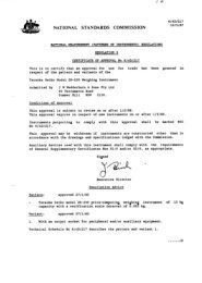
NATIONAL STANDARDS COMMISSION<br />
TECHNICAL SCHEDULE No 5/6A/9<br />
VARIATION No 1<br />
Pattern: <strong>Gilbarco</strong>/<strong>Epex</strong> <strong>Dual</strong>-<strong>purpose</strong> <strong>Driveway</strong> <strong>Flowmeter</strong> <strong>Model</strong> T132C<br />
Submittor : Engineering Products Pty Ltd, 418-428 Burnley Street,<br />
Burnley, Victoria, 3121,<br />
Date of Approval of Variants: 9 May 1974<br />
The modifications described in this schedule apply to the pattern and<br />
variants described in the following pages and figures of Certificate No<br />
5/6A/9 dated 2 April 1971:<br />
Pages 3 to 11 dated 2 April 1971<br />
Figures 5/6A/9 - 1 to 27 dated 2 April 1971<br />
All instruments conforming to this approval shall be marked<br />
“NSC No 5/6A/9”.<br />
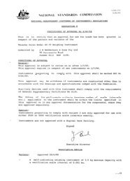
Description:<br />
This variation approves :<br />
1. The pattern and variants fitted with:<br />
(a) a $2 note acceptor (see Figures 2 8 and 2 9) ;<br />
(b) a $1 note acceptor which is similar to the $2 note acceptor.<br />
2. The pattern and variants converted to indicate in metric units in<br />
accordance with Appendix 14 of the General Specifications for<br />
Measuring Instruments to be Used for Trade.<br />
Test Specification:<br />
1. With no credit indicated, placing a $2 or $1 note as appropriate in<br />
the note acceptor should cause the lights on the coin unit to indicate<br />
the appropriate credit.<br />
2. The note acceptor will be inoperative when any credit is shown on the<br />
coin unit.<br />
22/5/74
-<br />
1<br />
-<br />
-<br />
1<br />
2<br />
3<br />
4<br />
9<br />
LO<br />
11<br />
12<br />
13<br />
14<br />
15<br />
16<br />
17<br />
L&l<br />
LO<br />
10<br />
21<br />
-<br />
2<br />
COMPONENTS<br />
Computer VR 1611<br />
with brackets<br />
Computer VR 1611<br />
without brackets<br />
Computer VR 1613<br />
with brackets<br />
Computer VR 1613<br />
without brackets<br />
Nozzle EP 4559<br />
Nozzle OPW 1ABV<br />
Hang-up<br />
Solenoid valve and<br />
by-pass pipe<br />
By-pass solenoid valve<br />
Distributor unit EP 5658<br />
Distributor’unit EP 5545<br />
Coin-receiving unit,<br />
2-shilling<br />
Coin-receiving unit,<br />
20-cent<br />
Coin-receiving unit,<br />
2-shilling/20-cent<br />
Coin tester, CT/MCS<br />
Coin tester, CT/MCS/DC<br />
Coin tester, CT/M/63<br />
(2-shilling)<br />
Coin tester, CT/M/63<br />
(20-cent)<br />
Coin tester, Tally-Ho<br />
Control unit, EP 5353<br />
Pressure bell<br />
FIGUHE; 5/6A/9 - 1<br />
3<br />
DATE<br />
APPROVED<br />
19 OCT 66<br />
26 JAN 68<br />
26 JAN 68 A A<br />
26 JAN 68<br />
19 OCT 66<br />
24 NOV 66<br />
19 OCT 66<br />
19 OCT 66<br />
26 JAN 68<br />
19 OCT 66<br />
26 JAN 68<br />
19 OCT 66<br />
19 OCT 66<br />
11 DEC 68<br />
19 OCT 66<br />
19 OCT 66<br />
19 OCT 66<br />
* - indicates required component<br />
4 5 6 7 8 9<br />
t VARIANTS?<br />
2;<br />
FOOT-<br />
NOTES F3<br />
u a<br />
E g g<br />
c<br />
::<br />
2 i? ;: % (0<br />
* A A<br />
A A<br />
A A<br />
* B B B B<br />
B B B B<br />
* * * * *<br />
* * *<br />
* * *<br />
* *<br />
* *<br />
* c c c c<br />
c c c c<br />
c c c c<br />
* D D D<br />
D D D<br />
D D D<br />
19 OCT 66 D D D<br />
11 DEC 68 D D D<br />
19 OCT 66 * * * * *<br />
19 OCT 66 * * * * *<br />
A - indicates alternative component, one of which is required<br />
B to D - as for A<br />
t - The pattern and variants T132C and T132B are manufactured by <strong>Gilbarco</strong><br />
Australia Ltd.<br />
Variant SS/VR is manufactured by Engineering Products Pty. Ltd.<br />
Variant 605 is manufactured by Wayne Pumps Australia Pty. Ltd.<br />
2/4/71<br />
Compatibility Table for Components Described<br />
in this Certificate
2/4/71<br />
FIGURE 5/6A/9 - 2<br />
<strong>Gilbarco</strong> T132C
2/4/71<br />
FIGURE 5/6A/9 - 3<br />
<strong>Gilbarco</strong> <strong>Model</strong> T132C with Panels Removed
2/4/71<br />
FIGURE 5/6A/9 - 4<br />
-- I<br />
D/S,?W..U~OR &NV<br />
/ ,<br />
<strong>Gilbarco</strong> <strong>Model</strong> T132C - Hydraulic Diagram
2/4/71<br />
FIGURE 5/6A/9 - 5<br />
Wayne <strong>Model</strong> 605 <strong>Self</strong>-<strong>serve</strong> Pump
FIGURE 5/6A/9 - 6<br />
Wayne <strong>Model</strong> 605 <strong>Self</strong>-<strong>serve</strong> Pump with Panels Removed<br />
2/4/71
2/4/71<br />
FIGURE 5/6A/9 - 7<br />
Veeder-Root 1611 Computer with Trip Lever and Cam<br />
BRACKET
2/4/71<br />
FIGURE 5/6A/9 - 8<br />
Veeder-Root 1611 Computer with Bracket<br />
on Starting Mechanism
2/4/71
2/4/71
,_ .
2/4/71
2/4/71<br />
FIGURE 5/6A/9 - 14<br />
<strong>Gilbarco</strong> <strong>Model</strong> T132C - Nozzle Rang-up
BY-<br />
-<br />
2/4/71<br />
FIGURE 5/6A/9 - 15<br />
Solenoid Valve and By-pass Pipe
2/4/71
z/4/71<br />
FIGURE 5/6A/9 - 17<br />
USE ONLY 24 PIECES<br />
lV@<br />
14lo<br />
16lo<br />
IIWSERT HERE<br />
IF COIN IS NOT ACCEPTED<br />
PRESS REJECT BUTTON<br />
AND INSERT AGAIN<br />
’ REJECT COINS*<br />
SELF SERVE I<br />
<strong>Epex</strong> Coin-receiving Unit - a-shilling<br />
h<br />
,<br />
i
L<br />
-<br />
FIGURE 5/6A/9 - 18<br />
USE ONLY 20 CENT COINS<br />
Y<br />
: $O-80@ “’<br />
$1-00.<br />
et-206<br />
!<br />
2/4/71<br />
$1-40.<br />
.$1;600<br />
$1~80.<br />
$2.ooa<br />
/<br />
.<br />
. LtigzEx<br />
.<br />
FCOlNlSNDTACCEPTED<br />
REJECT COINS<br />
*-.<br />
FRES REIEcr RuTroN<br />
AND INSERT AGAIN<br />
SELF &VE ‘..: / .<br />
* 2’ ,f<br />
_ :-/<br />
<strong>Epex</strong> Coin-receiving Unit - 20-cent
Z/4/71<br />
<strong>Epex</strong> CT/MCS Coin Tester
FIGURE 5/6A/9 - 20
COHENmY<br />
SOT<br />
2/4/71<br />
FIGURE 5/‘6A,‘9 - 21<br />
CO/NS ACCfPTED<br />
<strong>Epex</strong> CT/MCS Coin Tester - Schematic Diagram
2 /4/71<br />
FIGURE 5/6A/9 - 22<br />
Tally-Ho Coin Tester
.-<br />
2/4/71<br />
FIGURE 5/6A/9 - 23<br />
Tally-Ho Coin Tester in Frame
ACCEPT<br />
SWITCH<br />
CLOSED -II--<br />
STOP<br />
1<br />
ACCEPT<br />
&<br />
VIEW-A<br />
2/4/71<br />
1 il MAX<br />
32 -<br />
FIGURE 5/6A/S - 24<br />
,PAWL I------<br />
COIN CHECKING MECHANISM<br />
Tally-Ho Coin Tester - Schematic Diagram
2/4/71<br />
FIGURE 5/6A/9 - 25<br />
Tally-Ho Coin Tester, Acceptance Chute, Solenoid Stop<br />
and Microswitch
2/4/71<br />
<strong>Epex</strong> EP 5353 Control Unit
2/4/V<br />
.
L<br />
22/5/74<br />
$O-20e<br />
$0.406<br />
$0060a<br />
FIGURE 5/6A/9 - 28<br />
SO-800 ;NsERTfzo~olj;,,<br />
$I-ooa<br />
$l-206<br />
$1-40.<br />
W-60.<br />
Ardac $2 Note Acceptor<br />
0<br />
.<br />
REJECT COIN BUTTON<br />
9
THE LATCH WHICH LOCKS<br />
THE DRAWER SHALL NOT<br />
WIDTH OF GUARD NOT LESS<br />
THAN WIDTH OF DRAWER<br />
22 /5/74<br />
FIGURE 5/6A/S - 29<br />
NOTE DRAWER GUARD<br />
I I<br />
VIEW AA<br />
Interlock Position and Guard for Ardac Note Acceptor