Gilbarco/Epex Dual-purpose Self-serve Driveway Flowmeter Model ...
Gilbarco/Epex Dual-purpose Self-serve Driveway Flowmeter Model ...
Gilbarco/Epex Dual-purpose Self-serve Driveway Flowmeter Model ...

You also want an ePaper? Increase the reach of your titles
YUMPU automatically turns print PDFs into web optimized ePapers that Google loves.
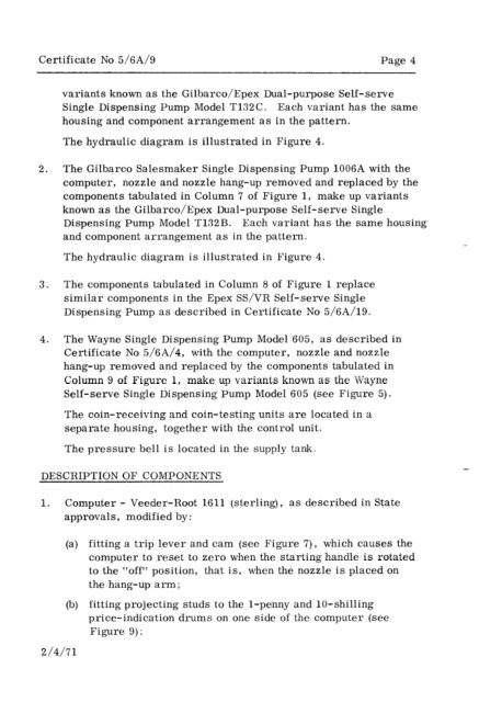
Certificate No 5/6A/9 Page 4<br />
variants known as the <strong>Gilbarco</strong>/<strong>Epex</strong> <strong>Dual</strong>-<strong>purpose</strong> <strong>Self</strong>-<strong>serve</strong><br />
Single Dispensing Pump <strong>Model</strong> T132C. Each variant has the same<br />
housing and component arrangement as in the pattern.<br />
The hydraulic diagram is illustrated in Figure 4.<br />
2. The <strong>Gilbarco</strong> Salesmaker Single Dispensing Pump 1006A with the<br />
computer, nozzle and nozzle hang-up removed and replaced by the<br />
components tabulated in Column 7 of Figure 1, make up variants<br />
known as the <strong>Gilbarco</strong>/<strong>Epex</strong> <strong>Dual</strong>-<strong>purpose</strong> <strong>Self</strong>-<strong>serve</strong> Single<br />
Dispensing Pump <strong>Model</strong> T132B. Each variant has the same housing<br />
and component arrangement as in the pattern.<br />
The hydraulic diagram is illustrated in Figure 4.<br />
3. The components tabulated in Column 8 of Figure 1 replace<br />
similar components in the <strong>Epex</strong> SS/VR <strong>Self</strong>-<strong>serve</strong> Single<br />
Dispensing Pump as described in Certificate No 5/6A/19.<br />
4. The Wayne Single Dispensing Pump <strong>Model</strong> 605, as described in<br />
Certificate No 5/6A/4, with the computer, nozzle and nozzle<br />
hang-up removed and replaced by the components tabulated in<br />
Column 9 of Figure 1, make up variants known as the Wayne<br />
<strong>Self</strong>-<strong>serve</strong> Single Dispensing Pump <strong>Model</strong> 605 (see Figure 5).<br />
The coin-receiving and coin-testing units are located in a<br />
separate housing, together with the control unit.<br />
The pressure bell is located in the supply tank.<br />
DESCRIPTION OF COMPONENTS<br />
1. Computer - Veeder-Root 1611 (sterling), as described in State<br />
approvals, modified by:<br />
2/4/71<br />
(a) fitting a trip lever and cam (see Figure 7)) which causes the<br />
computer to reset to zero when the starting handle is rotated<br />
to the “off” position, that is, when the nozzle is placed on<br />
the hang-up arm ;<br />
(b) fitting projecting studs to the l-penny and lo-shilling<br />
price-indication drums on one side of the computer (see<br />
Figure 9);