Surgical Instruments: Converting from Metal to Plastic - Mack Molding
Surgical Instruments: Converting from Metal to Plastic - Mack Molding
Surgical Instruments: Converting from Metal to Plastic - Mack Molding

Create successful ePaper yourself
Turn your PDF publications into a flip-book with our unique Google optimized e-Paper software.
MOLDING >><br />
<strong>Surgical</strong> <strong>Instruments</strong>:<br />
<strong>Converting</strong> <strong>from</strong><br />
<strong>Metal</strong> <strong>to</strong> <strong>Plastic</strong><br />
Designers face many challenges when engineering plastics in<strong>to</strong> surgical<br />
instruments that have traditionally been machined or cast metal.<br />
Randy Pell<br />
Many companies find it difficult <strong>to</strong> reduce the cost of<br />
metal surgical instruments. The production, cleaning,<br />
and sterilization of metal components can be<br />
expensive, and there is little that can be squeezed out of the<br />
equation. An alternative is <strong>to</strong> shift <strong>from</strong> metal <strong>to</strong> plastic,<br />
which can be injection molded. Injection-molded plastic<br />
offers several advantages over metal components. Not only<br />
can components be made at a lower cost, but, for disposable<br />
ones, switching <strong>to</strong> plastic can even reduce sterilization<br />
requirements.<br />
<strong>Plastic</strong> components are lightweight and can also be colorcoded,<br />
making packaging more efficient. But companies<br />
need <strong>to</strong> be able <strong>to</strong> overcome the challenges—including material<br />
selection, part <strong>to</strong>lerances, design, and <strong>to</strong>oling—that<br />
can arise when engineering plastics in<strong>to</strong> surgical instruments.<br />
Reusable versus Disposable<br />
The first step is deciding whether <strong>to</strong> design instruments<br />
<strong>to</strong> be reusable or whether <strong>to</strong> make them disposable. The<br />
material requirements for each are quite different. Reusable<br />
instruments are most likely going <strong>to</strong> be steam sterilized. For<br />
this type of application, manufacturers should select plastic<br />
resins that can be au<strong>to</strong>claved. It’s important <strong>to</strong> note,<br />
however, that au<strong>to</strong>clavable resins are much more expensive<br />
than those that can be used for disposables. <strong>Instruments</strong><br />
also need <strong>to</strong> be strong and impact resistant, which further<br />
limits the selection of resins. Some resins may be used <strong>to</strong><br />
form handles, however. Handles can benefit <strong>from</strong> soft<strong>to</strong>uch<br />
materials like thermoplastic elas<strong>to</strong>mers (TPEs) or<br />
Randy Pell is senior staff design engineer for <strong>Mack</strong><br />
<strong>Molding</strong> Co., a cus<strong>to</strong>m plastics molder and contract manufacturer<br />
based in Arling<strong>to</strong>n, VT.<br />
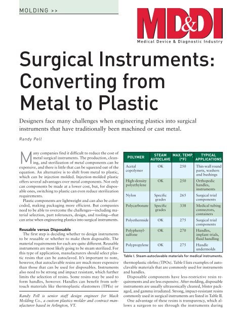
POLYMER<br />
STEAM MAX. TEMP. TYPICAL<br />
AUTOCLAVE (°F) APPLICATIONS<br />
Acetal OK 250 Thin-wall round<br />
copolymer parts, washers<br />
and bushings<br />
High-density OK 250 Orthopedic<br />
polyethylene handles,<br />
instruments<br />
Nylon Specific 265 <strong>Surgical</strong> trial<br />
grades components<br />
Polycarbonate Specific 338 Medical tubing<br />
grades connec<strong>to</strong>rs,<br />
containers<br />
Polyethermide OK 275 <strong>Surgical</strong> trial<br />
components<br />
Polyphenyl- OK 270 Handles,<br />
sulfone implant trials,<br />
fluid handling<br />
Polypropylene OK 275 Handle<br />
undermolds<br />
Table I. Steam-au<strong>to</strong>clavable materials for medical instruments.<br />
thermoplastic olefins (TPOs). Table I lists examples of au<strong>to</strong>clavable<br />
materials that are commonly used for instruments<br />
and handles.<br />
Disposable components have less-restrictive resin requirements<br />
and are less expensive. After molding, disposable<br />
instruments are usually ultrasonically cleaned, blister packaged,<br />
and gamma irradiated. Strong, impact-resistant resins<br />
commonly used in surgical instruments are listed in Table II.<br />
One advantage of these resins is transparency, which allows<br />
a surgeon <strong>to</strong> see through the instruments during
MOLDING >><br />
POLYMER<br />
GAMMA MAX. RADS TYPICAL<br />
RADIATION (Mrd) APPLICATIONS<br />
Acrylonitrile<br />
butadiene<br />
styrene<br />
OK 5 Trays, handles<br />
Acrylic OK 5 Orthopedic<br />
handles,<br />
instruments<br />
Nylon OK 10 <strong>Surgical</strong> trial<br />
components<br />
Polycarbonate OK 10 Medical tubing<br />
connec<strong>to</strong>rs,<br />
containers<br />
Polypropylene OK 6 Handle<br />
undermolds,<br />
syringes<br />
Table II. Gamma-sterilizable materials for medical instruments.<br />
surgery. But transparent or translucent resins may experience<br />
a color shift during the gamma sterilization process, so<br />
it’s important <strong>to</strong> work with the material supplier <strong>to</strong> achieve<br />
the desired results. Another advantage is color coding, which<br />
can be useful with series of parts that are different sizes or<br />
that are used with other components. Color coding allows<br />
a surgeon or other operating-room personnel <strong>to</strong> quickly<br />
identify the appropriate equipment.<br />
Part Tolerance Requirements<br />
Part <strong>to</strong>lerance requirements (first-article inspection) can<br />
be one of the most difficult challenges a team faces with plastic<br />
instruments, especially for companies that have little or<br />
no experience with the <strong>to</strong>lerances of plastic components.<br />
Companies that are used <strong>to</strong> making metal components are<br />
familiar with the repeated machining, multiple setups, and<br />
the different methods required for them. But the <strong>to</strong>lerance<br />
requirements for metal instruments are completely different<br />
<strong>from</strong> those for plastic molded components. The device must<br />
be properly designed in order <strong>to</strong> have proper function in<br />
spite of these variations.<br />
Each organization must develop a method for approving<br />
the dimensional differences <strong>to</strong> determine what will be an acceptable<br />
molded product. Injection-molded-plastic suppliers<br />
should be able <strong>to</strong> provide realistic expectations for part<br />
print generation, first-article reports, and capability studies.<br />
Because metal parts are machined, there is typically a dimension<br />
for every piece of geometry with <strong>to</strong>lerances that are<br />
suitable for drilling, milling, grinding, etc. For example, a<br />
0.250-in.-diam drilled and bored hole would have a <strong>to</strong>lerance<br />
of +0.006/–0.000 in. This <strong>to</strong>lerance works well for a<br />
machinist, but in molding, all geometry should be in the<br />
middle of the <strong>to</strong>lerance. If this were a 0.250-in. diameter<br />
hole in a plastic part, the <strong>to</strong>lerance would look more like<br />
±0.003 in. The amount of <strong>to</strong>lerance remains the same, but<br />
the hole can stay within the <strong>to</strong>lerance range as the plastic<br />
process varies throughout the production run. It is extremely<br />
important for engineers designing a 3-D database <strong>to</strong> make<br />
sure all the geometry resides in the center of the feature’s <strong>to</strong>lerance<br />
zone.<br />
As for part prints, make three separate sets <strong>to</strong> move parts<br />
through the approval process quickly and easily.<br />
The first set is a completely dimensioned print (just like<br />
metal prints), including every geometry feature dimensioned.<br />
The quality department, which is familiar with metal-part<br />
first articles, will need this set <strong>to</strong> approve the parts. The<br />
features should only have <strong>to</strong> be measured once <strong>to</strong> verify<br />
whether the mold is producing the parts according <strong>to</strong> specification.<br />
The process needs <strong>to</strong> be verified with a design of<br />
experiments (DOE), which is explained in more detail<br />
below.<br />
The second set contains only the critical geometry dimensions—the<br />
geometry features that interact with other<br />
components vital <strong>to</strong> the function of the part. These dimensions<br />
will be checked each time the part is molded <strong>to</strong> verify<br />
that the part will function correctly.<br />
The third set of prints contains only a few dimensions—<br />
only those features affected most by the molding process,<br />
such as hard-<strong>to</strong>-fill thin areas, overall width and height,<br />
and the weight range of the parts. This print is for inprocess<br />
checks at the molder.<br />
Design of Experiments<br />
A DOE needs <strong>to</strong> be run on the molding process <strong>to</strong> determine<br />
the limits of process variations (the process window)<br />
allowable within the <strong>to</strong>lerance zone. This DOE uses<br />
different parameters of the molding process, which could<br />
include resin melt temperature, mold temperature, injection<br />
pressure, injection speed, injection profile, injection<br />
time, and cooling time. It is important <strong>to</strong> include all those<br />
parameters that are necessary <strong>to</strong> prove that the process is<br />
acceptable.<br />
Once the DOE is finished, a first article can be completed<br />
on the molded parts <strong>to</strong> determine which molding<br />
process will yield the best in-<strong>to</strong>lerance part. Molded parts<br />
will have uniform dimensions for the rest of the <strong>to</strong>ol’s life,<br />
provided that the <strong>to</strong>ol isn’t damaged. Parts will vary, however,<br />
within the process parameters established in the DOE,<br />
so in-process checks must be used. In-process checks consist<br />
of measuring the critical dimensions of the part<br />
throughout the molding production run, typically once<br />
per hour.<br />
<strong>Plastic</strong> Part Geometry: Strength and Moldability<br />
The strength properties of metal are generally superior <strong>to</strong><br />
those of plastic, so it’s important <strong>to</strong> determine whether a<br />
plastic resin is available that meets the requirements of the<br />
instrument’s intended use. If the instrument is going <strong>to</strong> be<br />
pried with a long lever arm or impacted by a hammer, plastic<br />
may not be optimal. But if the <strong>to</strong>ol is simply a cutting<br />
guide or a static spacer, then plastic may be suitable.<br />
Filled plastic materials provide much more flexural<br />
strength than unfilled resisns. Their strength can be close <strong>to</strong><br />
the strength of some metals. Certain resins can also be molded<br />
in thick sections. For example, a polycarbonate can be<br />
straight injection molded up <strong>to</strong> approximately 0.180-in.<br />
wall sections. Glass-filled nylon can be molded up <strong>to</strong> a<br />
0.375-in. wall thickness. Certain additives, such as structural<br />
foam, can also yield thicker parts. These additives can be
MOLDING >><br />
Figure 1. An unsupported wall that must remain perpendicular<br />
can be created by adding a groove at the intersection of the<br />
perpendicular and main walls.<br />
Section through<br />
Center of Boss<br />
Scale 1 +<br />
Unsupported Wall<br />
Scale 2 +<br />
Groove Detail<br />
Add Groove<br />
Detail at Intersection<br />
Figure 2. To avoid sink around a thick boss, a groove can be<br />
inserted through the center of the boss.<br />
combined with many different types of plastic resins and are<br />
able <strong>to</strong> withstand sterilization after molding. The structural<br />
foam additive can improve impact strength when used with<br />
certain types of resins and can keep the part <strong>from</strong> sinking or<br />
warping.<br />
<strong>Plastic</strong> parts have a tendency <strong>to</strong> warp and sink in certain<br />
areas, and so they must be designed <strong>to</strong> overcome these tendencies.<br />
One difficult piece <strong>to</strong> produce in a part is an unsupported<br />
wall that remains perpendicular. If this wall can’t<br />
be designed with a supporting rib, a feature can be added<br />
that removes the thick area created at the intersection of the<br />
perpendicular and main walls (see Figure 1). A thick area<br />
stays hotter longer, which increases shrinkage in the part and<br />
pulls the wall inward.<br />
Another potential problem is sink around thick bosses.<br />
For example, a large-diameter boss with thick walls for<br />
threaded inserts or screw holes for self-tapping screws usually<br />
becomes <strong>to</strong>o thick and tends <strong>to</strong> sink. Use the same type<br />
of feature described above for the wall intersection. The<br />
feature will be made around the boss at its intersection <strong>to</strong><br />
the main wall (see Figure 2). Another option is <strong>to</strong> use structural<br />
foam, which can reduce sink in thick parts and can reduce<br />
molded-in stress, which causes warpage.<br />
For an example of a metal-<strong>to</strong>-plastic instrument applica-<br />
tion see Figure 3, an ankle clamp designed by John Grecco<br />
of Stryker Orthopaedics. The clamp is used in knee replacement<br />
surgery. The yoke and flippers were previously<br />
made of stainless steel, and the instrument assembly needed<br />
<strong>to</strong> sustain multiple steam au<strong>to</strong>claves. The designer determined<br />
that the strength of a polysulfone resin would be<br />
sufficient <strong>to</strong> meet the instrument’s requirements. In addition,<br />
the high-heat properties of polysulfone would allow it <strong>to</strong><br />
withstand the temperatures of steam au<strong>to</strong>claving. In its new,<br />
plastic design, the yoke attaches <strong>to</strong> a metal component that<br />
interacts with the rest of the instrument. The flippers are<br />
simply a pair of molded parts, but require a nice press fit<br />
over the pivot bushings. A <strong>to</strong>rsion spring interacts with<br />
these two flippers.<br />
Overmolding <strong>Metal</strong> with <strong>Plastic</strong><br />
It is possible <strong>to</strong> reduce costs in instruments by simplifying<br />
the metal-machined component with a plastic overmold<br />
in areas that do not need <strong>to</strong> be metal. In some cases, a part<br />
has complex geometry <strong>to</strong> fit the con<strong>to</strong>urs of the human<br />
body but only has one area that connects <strong>to</strong> a metal handle.<br />
For these situations, the entire complex machining process<br />
can be eliminated by molding a plastic part and making the<br />
connection with a metal insert. Or perhaps the component<br />
must attach <strong>to</strong> another instrument using magnetism; simply<br />
overmold or insert a magnet in<strong>to</strong> the molded part <strong>to</strong> achieve<br />
this requirement.<br />
The plastic part needs <strong>to</strong> seal off on some of the metal insert<br />
surfaces <strong>to</strong> hold it in place while molding. The injection<br />
pressure of the plastic resin entering the cavity is typically<br />
quite high and will move a metal component around it if it<br />
is not retained securely. Sealing off the metal insert surfaces<br />
can be a challenge for the <strong>to</strong>olmaker, since the surfaces need<br />
<strong>to</strong> be held <strong>to</strong> a very small <strong>to</strong>lerance. This <strong>to</strong>lerance would<br />
be ±0.002 in. for typical resins and ±0.0005 in. for TPE-type<br />
resins. Springs in the injection mold can sometimes increase<br />
the seal-off <strong>to</strong>lerance by making the seal-off area an insert.<br />
For example, if a metal component has a ±0.0005-in. <strong>to</strong>lerance<br />
in the seal-off area, a <strong>to</strong>ll insert with springs that is<br />
built <strong>to</strong> the shape of the metal component can increase that<br />
<strong>to</strong>lerance <strong>to</strong> ±0.001 in. The insert is allowed <strong>to</strong> move inside<br />
the <strong>to</strong>ol and is supported with a strong spring that will<br />
withstand injection pressure while molding. Be sure it will<br />
be able <strong>to</strong> adjust <strong>to</strong> the amount of <strong>to</strong>lerance in the inserted<br />
machined-metal component. Plan <strong>to</strong> replace this insert easily,<br />
since it will be a high-wear item.<br />
Handles can be overmolded in an ergonomic shape that<br />
fits the surgeon’s hand but that can still interact with attachments<br />
or be hit with a mallet. A simple shaft of metal<br />
can be overmolded with a plastic resin <strong>to</strong> form the ergonomic<br />
shape. Handles can be made with a soft-<strong>to</strong>uch<br />
grip, resulting in a double-shot overmolded handle.<br />
The end shut-off geometry on this type of handle is critical<br />
because of TPE-like materials’ tendency <strong>to</strong> flash in<strong>to</strong>, or<br />
over, gaps that are 0.0005 in. Machine the shut-off area <strong>to</strong><br />
±0.0005 in. or better, and consider the spring features discussed<br />
as a necessity.<br />
If the handle is a reusable item that needs <strong>to</strong> be sterilized,<br />
create a part that has extremely small, or no, gaps that
MOLDING >><br />
Figure 3. This ankle clamp designed by John Grecco of Stryker<br />
Orthopaedics attaches the plastic yoke <strong>to</strong> a metal component<br />
that interacts with the rest of the instrument.<br />
might trap contaminants <strong>from</strong> the surgical procedure. Work<br />
with the metal supplier and molding vendor <strong>to</strong> determine a<br />
feature in the metal that will hold the TPE resin in place so<br />
that it can’t pull away and leave a gap.<br />
Pro<strong>to</strong>typing<br />
Account for extra pro<strong>to</strong>typing time and the additional<br />
associated costs. It’s very important <strong>to</strong> make sure that<br />
parts fit up <strong>to</strong> mating components. This can be done using<br />
any of the plastic pro<strong>to</strong>type methods, such as stereolithography<br />
or selective laser sintering. If the part or <strong>to</strong>ol<br />
has snap features, consider 3-D ABS-type printers so it can<br />
be made <strong>from</strong> amorphous-like resins. There are now<br />
pro<strong>to</strong>type materials that are soft and flexible like TPEs<br />
or TPOs.<br />
Next, build a simple <strong>to</strong>ol in a single-cavity configuration<br />
so that the intended plastic resin can be molded. The <strong>to</strong>ol<br />
can be made in an epoxy <strong>to</strong>ol process for just a few parts,<br />
or it can be made out of steel or aluminum. If there are undercuts<br />
that would be made with cam slides or angled lifters,<br />
make these features with hand-loaded cores or use secondary<br />
operations such as milling or drilling.<br />
Conclusion<br />
Reducing the cost of metal surgical instruments may require<br />
switching <strong>to</strong> plastic. Compared with metal, injectionmolded<br />
plastic offers several advantages, including lower<br />
cost and reduced sterilization requirements. However, manufacturers<br />
that are looking <strong>to</strong> plastic as an alternative must<br />
carefully consider material selection, part <strong>to</strong>lerances, design,<br />
and <strong>to</strong>oling.<br />
The molding vendor will play a vital role in developing<br />
plastic instruments. Another important member of the<br />
team will be the mold maker. The molder may have inhouse<br />
mold building or may use a stable of outside <strong>to</strong>oling<br />
vendors. Either way, the molder is ultimately responsible<br />
for ensuring the mold can produce a part that meets<br />
all specifications. Manufacturers that address these challenges<br />
can often make a smooth transition <strong>from</strong> metal <strong>to</strong><br />
plastic instruments. ■<br />
Reprint <strong>from</strong> Medical Device & Diagnostic Industry, Oc<strong>to</strong>ber 2006 • Copyright © 2006 Canon Communications LLC