Gas-Assist Injection Molding: An Innovative Medical ... - Mack Molding
Gas-Assist Injection Molding: An Innovative Medical ... - Mack Molding
Gas-Assist Injection Molding: An Innovative Medical ... - Mack Molding

Create successful ePaper yourself
Turn your PDF publications into a flip-book with our unique Google optimized e-Paper software.
COVER STORY >> MOLDING<br />
<strong>Gas</strong>-<strong>Assist</strong> <strong>Injection</strong><br />
<strong>Molding</strong>: <strong>An</strong> <strong>Innovative</strong><br />
<strong>Medical</strong> Technology<br />
In certain medical device applications, gas-assist molding can<br />
provide solutions that conventional injection molding cannot.<br />
Michael Hansen<br />
<strong>Gas</strong>-assist injection molding was developed several<br />
years ago to overcome the limitations of conventional<br />
injection molding. A molding technique that requires<br />
special knowledge, like gas-assist, usually takes some time<br />
to move into new industries. Accordingly, the gas-assist process<br />
has been adopted by several industries during the last<br />
few years, and this innovative technology is now making inroads<br />
in the medical industry, offering new technical and creative<br />
possibilities to device OEMs.<br />
The process features a unit that introduces nitrogen gas<br />
into a mold cavity after it has been filled with plastic. The<br />
compressed nitrogen displaces a portion of the molten plastic<br />
when injected into the cavity. The result is hollow parts<br />
that are light and relatively inexpensive to make.<br />
Designers can use gas-assist molding to create thin-walled<br />
parts. Such parts can be molded with low clamp tonnage,<br />
which reduces both tooling cost and required injection molding<br />
machine size. The gas-assist technique is ideal for adding<br />
thick, hollowed-out sections to otherwise thin-walled parts.<br />
The process improves upon polymer fill and packing techniques<br />
and boosts melt-flow length. A designer can create<br />
larger, more-complex parts with fewer injection gates than<br />
conventional molding, while minimizing costs incurred with<br />
complicated hot-runner systems. In addition, the sections<br />
that are cored out cool rapidly, reducing overall cycle time.<br />
The stand-alone gas unit is wired into the injection<br />
molding machine. It uses process signals to time and control<br />
the gas-assist process sequence. The gas unit is also<br />
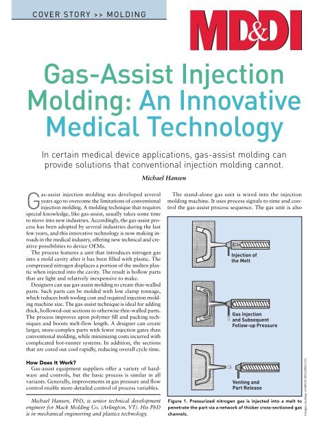
<strong>Injection</strong> of<br />
the Melt<br />
<strong>Gas</strong> <strong>Injection</strong><br />
and Subsequent<br />
Follow-up Pressure<br />
How Does It Work?<br />
<strong>Gas</strong>-assist equipment suppliers offer a variety of hardware<br />
and controls, but the basic process is similar in all<br />
variants. Generally, improvements in gas pressure and flow<br />
control enable more-detailed control of process variables.<br />
Michael Hansen, PhD, is senior technical development<br />
engineer for <strong>Mack</strong> <strong>Molding</strong> Co. (Arlington, VT). His PhD<br />
is in mechanical engineering and plastics technology.<br />
Venting and<br />
Part Release<br />
Figure 1. Pressurized nitrogen gas is injected into a melt to<br />
penetrate the part via a network of thicker cross-sectioned gas<br />
channels.<br />
Images courtesy of MACK MOLDING CO.
MOLDING >><br />
Solidified Layer<br />
Prefill with Melt<br />
<strong>Gas</strong> <strong>Injection</strong> Phase<br />
Hot Core<br />
Expanding <strong>Gas</strong> Bubble<br />
P <strong>Gas</strong><br />
Solidified Layer<br />
P <strong>Gas</strong><br />
Cooling after <strong>Gas</strong> <strong>Injection</strong><br />
Figure 2. During melt and gas injection, some of the polymer<br />
melt solidifies at the outer wall and forms a solid layer of resin.<br />
linked to a nitrogen source (e.g., bottles, a liquid nitrogen<br />
tank, or a nitrogen generator). The nitrogen source can be<br />
located close to the gas unit or can be part of a central<br />
plant system.<br />
The gas can be injected into the polymer melt either<br />
through a molding machine nozzle or through a gas nozzle.<br />
With a machine nozzle, the nitrogen gas flows through<br />
sprue, runners, and gates before entering the part. With a gas<br />
nozzle, the gas flows directly into the part.<br />
The Process Sequence<br />
Figure 1 shows the principal gas-assist process sequence.<br />
Pressurized nitrogen gas injected into the melt penetrates the<br />
part via a network of thicker, cross-sectioned gas channels.<br />
The process can accomplish partial or volumetric fillings of<br />
a cavity with polymer melt, as in injection molding. Next is<br />
the injection of compressed gas. Nitrogen is usually used because<br />
of its availability, cost, and inertness. Some processes<br />
will, in addition, use overspill cavities for structural or<br />
cosmetic reasons. Some resins require a complete filling of<br />
the tool prior to applying the gas to produce cosmetically acceptable<br />
parts. 1,2<br />
After the gassing phase, the pressure is released either by gas<br />
recycling or by releasing the gas into the atmosphere. As soon<br />
as ambient pressure is reached, the molded part can be ejected.<br />
Figure 2 illustrates the process of forming a part using gasassist<br />
molding. During melt and gas injection, some of the<br />
polymer melt solidifies at the outer walls and forms a solid<br />
layer of resin. This layer grows during the delay between the<br />
polymer and gas injection. During gas injection, the compressed<br />
nitrogen flows through the plastic core and displaces<br />
a portion of the molten plastic. Normally, after plastic<br />
is injected and fills the cavities, the molding machine<br />
goes into a packing stage to prevent void formation. With<br />
gas-assist molding, the gas performs the packing, and the<br />
voids are intentionally created to reduce part weight and<br />
minimize cycle time.<br />
Nitrogen gas has a lower viscosity than the polymer melt.<br />
For this reason, the pressure drop over the flow length of the<br />
gas bubble is much lower than over the flow length of a<br />
molded part. The pressure drop in the holding and packing<br />
phase influences the shrinkage across the part and the ability<br />
to pack a part. Shrinkage differences promote buildup of<br />
internal molded-in stresses and subsequently influence the<br />
warpage of a part significantly. The gas-assist process reduces<br />
internal stresses and warping and thus improves part<br />
quality. It provides a higher and more evenly distributed<br />
packing pressure across the part, resulting in better overall<br />
part flatness.<br />
<strong>Gas</strong> always takes the path of least flow resistance; it<br />
flows into the direction of the melt front. The gas channel’s<br />
course goes through the cores of thicker or hotter portions<br />
of the part. The advancing gas pushes the displaced molten<br />
plastic toward the melt front to fill and later pack those<br />
areas in the cavity. After a complete volumetric filling of the<br />
cavity, the gas pressure replaces the holding pressure, which<br />
compensates for the shrinkage. The internal gas pressure<br />
keeps the part in good contact with the mold walls. The<br />
hotter melt core of the part has the most shrinkage potential,<br />
and because of the applied gas pressure, the cooling<br />
melt shrinks the most in the hot core section. The shrinkage<br />
becomes less toward the mold wall. At the tip of the gas<br />
bubble, a so-called shrinkage lance forms because of the differential<br />
shrinkage in different layers over the cross section<br />
of the part. The lance prevents the molded part from sinking<br />
in.<br />
Figure 3 illustrates the machine cycle of the gas-assist<br />
process. It’s important to note the efficiencies that can be<br />
gained using this process. First, gas-recycling technology is<br />
Remaining<br />
Cooling Time<br />
Unit Back<br />
Part Ejection<br />
Open Mold<br />
<strong>Gas</strong> Pressure Release<br />
Begin Cycle<br />
Close Mold<br />
Unit Forward<br />
Resin <strong>Injection</strong><br />
Delay Time<br />
<strong>Gas</strong> <strong>Injection</strong> Phase<br />
<strong>Gas</strong> Pressure<br />
Holding Phase<br />
Figure 3. Machine cycle of the gas-assist injection process.
MOLDING >><br />
• Full-shot molding that pushes resin back into barrel<br />
(similar to the overspill technique using the machine<br />
barrel as the overspill cavity).<br />
• External gas molding (adding a layer of nitrogen gas to<br />
the part surface adjacent to the cosmetic surface after<br />
complete fill of the cavity).<br />
(a) Rod-Shaped Parts<br />
(b) Large Cover-Shaped Parts<br />
(c) Complex Parts with<br />
Localized Heavy Sections<br />
Figure 4. Three main categories of molded parts are especially<br />
appropriate for gas-assist injection molding.<br />
fully developed and can be used in production, thereby reducing<br />
costs. Also, when gassing through the machine nozzle<br />
(rather than directly into the part), the runner system can<br />
be sealed after pressure release. During the remaining cooling<br />
time, the injection unit meters the shot size for the next<br />
cycle, which reduces cycle time.<br />
Many part designers still see the gas-assist process as a solution<br />
only for simple, hollow, tube-shaped parts. In practice,<br />
however, it is much more versatile and can often solve<br />
many of the problems inherent in conventional injection<br />
molding. Some of the benefits include thin-walled parts and<br />
fast cooling for reduced cycle times. Less required clamp<br />
tonnage means smaller molding machine size. In addition,<br />
gas-assist molding minimizes tooling costs and can make<br />
large, complex parts using fewer gates and less-complicated<br />
hot-runner systems than traditional machines.<br />
There are different gas-assist injection molding techniques,<br />
including the following:<br />
• Short-shot molding (prefill of cavity with melt, followed<br />
by gas injection).<br />
• Full-shot molding (complete fill of cavity with melt,<br />
followed by gas injection).<br />
• Full-shot molding with overspill (complete fill of cavity<br />
with melt, followed by gas injection and opening of<br />
overspill cavities).<br />
In addition, there are variants of these techniques. One includes<br />
a process that uses low-temperature nitrogen gas to<br />
create a gas flow through the part for an additional cooling<br />
effect.<br />
For some resins, the short-shot method cannot be used because<br />
of cosmetic surface requirements. Full-shot processes<br />
that have additional cavities into which the resin in the core<br />
is evacuated generally provide more control over the process.<br />
Geometric Categories<br />
Three main categories of molded parts are especially appropriate<br />
for gas-assist technology. The first group—tubeor<br />
rod-shaped parts—typically includes handles and foot<br />
pedals (see Figure 4a).<br />
The second category consists of large, cover-shaped structural<br />
parts. Such parts are made with a network of gas channels<br />
that is often combined with the rib structure of the<br />
parts. Examples include side panels and covers for medical<br />
devices (see Figure 4b).<br />
The third group involves complex parts with both thin<br />
and thick sections. The gas-assist process is used for part integration<br />
by consolidating several assembled parts into a single<br />
design (Figure 4c). Typical examples would be handles<br />
with mounting sections or tray-like parts with thick perimeter<br />
sections.<br />
Because the flow path for tube- or rod-shaped parts is<br />
one-dimensional, a good distribution of the gas channel can<br />
be ensured. With these parts, uniform wall thickness<br />
It is very important to understand<br />
and appropriately design the<br />
filling pattern before injecting<br />
the gas.The design should be<br />
adapted according to the planned<br />
or existing gas channel network.<br />
throughout the cross section is the goal. The resulting wall<br />
thickness is a function of the viscosity and temperature distribution<br />
within the melt when the nitrogen gas is injected.<br />
For extended thin-walled parts, the desired distribution of<br />
nitrogen gas can only be achieved through a geometrical<br />
adaptation. These parts require some ribbing to create a network<br />
of gas channels. Injecting nitrogen during the gassing<br />
and holding phases of the process forms the hollow spaces.<br />
Ultimately, the process produces parts with reduced internal<br />
stresses and, consequently, less warpage. <strong>Gas</strong> penetration<br />
into the adjacent thin-wall sections should be avoided. It is
MOLDING >><br />
Material Data<br />
• Rheological Behavior<br />
• Thermal Behavior<br />
Process Parameters<br />
• Delay Time<br />
• <strong>Gas</strong>sing Time<br />
• <strong>Gas</strong> Profile<br />
• Degree of Prefill<br />
• Melt/Mold Wall Temperature<br />
Part<br />
• Geometry Categories<br />
• <strong>Injection</strong> Point Location<br />
• Part Design<br />
Process <strong>An</strong>alysis<br />
• Mathematical Modeling<br />
• Experiments<br />
• Finite Element Methods<br />
Machine Data<br />
• <strong>Gas</strong>sing Position/Location<br />
• Concept of <strong>Gas</strong>sing Unit<br />
• <strong>Gas</strong> Profile<br />
• Process Variant<br />
Figure 5. Five important factors influence the production of gas-assist-injection-molded parts.<br />
Figure 6. Using gas-assist molding ensured consistent wall<br />
thicknesses over the length of Alcon’s Infiniti main handle.<br />
Figure 7. The gas evenly hollowed out the Infiniti’s side handle.<br />
It is a closed-loop part, so overspill technology was required.<br />
possible to determine the probability of gas penetration into<br />
adjacent wall sections by examining part design, gas channel<br />
geometry, the relation of wall thickness to gas channel dimensions,<br />
and the gas pressure itself.<br />
Optimizing Parts and Tool Design<br />
Five significant factors influence the production of gasassist-injection-molded<br />
parts (see Figure 5). These factors<br />
and their interdependencies are the most important checkpoints<br />
for part and tool design.<br />
It is critical to adapt part design to the gas-assist injection<br />
molding process. It is essential to take the specific processing<br />
requirements and conditions into account in the early<br />
stages of part concept and design. Doing so can reduce the<br />
necessary adaptation work to a minimum.<br />
It is also very important to understand and appropriately<br />
design the filling pattern before injecting the gas. The design<br />
should be adapted according to the planned or existing<br />
gas channel network. The gas channel layout depends on the<br />
size, shape, course, and length of the gas channels. It also depends<br />
on the location of the injection points and geometry<br />
and the needle position for gassing. Manufacturers can obtain<br />
this information through iterative testing or by using<br />
mold-filling simulation programs. Here, the processing parameters,<br />
as well as rheological and thermal behavior of<br />
the polymer, are very important.<br />
Application Examples<br />
In the following examples, parts fall within one of the<br />
three categories shown in Figure 4.
MOLDING >><br />
Figure 8. To make a Datascope main handle, a number of gas nozzles were timed to<br />
control the introduction of the gas in different locations.<br />
Figure 9. This keyboard for Philips <strong>Medical</strong> Systems combines<br />
a thick-walled injection-molded part with attached handles.<br />
Figure 10. The gas channels ensured that the gas hollowed out<br />
and packed the base of the bosses on a clamshell for Zoll.<br />
<strong>Gas</strong>-<strong>Assist</strong> Handles with Attached<br />
Thinner Sections. Because<br />
of the thick cross section of the<br />
molded handles, a gas-assist process<br />
is used to mold a hollow,<br />
tube-shaped part with a highly<br />
cosmetic surface and a consistent<br />
internal gas channel. The molding<br />
process ensures mechanical and<br />
structural integrity.<br />
Figure 6 shows the Infiniti<br />
main handle by Alcon Laboratories<br />
(Irvine, CA). The handle is<br />
sectioned to show the hollowed<br />
out center in its tube-shaped<br />
portion. It is important to note<br />
that the wall thickness is consistent<br />
over the length of the handle<br />
and around its perimeter.<br />
This optimizes the mechanical<br />
properties of the molded part.<br />
Thin-walled, ribbed mounting<br />
sections located at both ends of<br />
the handle mean that the handle could be attached to the<br />
main unit.<br />
The Alcon handle needed high structural strength combined<br />
with impact resistance requirements and good cosmetic<br />
surface finishes. These specifications required overspill<br />
technology. The part is completely filled and packed<br />
prior to using nitrogen gas to push the hot melt into an additional<br />
cavity.<br />
The Alcon Infiniti side handle in Figure 7 is cut open<br />
through the entire length of the part, illustrating the extent<br />
to which the gas evenly hollowed out the cavity. The part<br />
needed to meet the same design requirements as the main<br />
handle. Because the side handle is designed as a closed-loop<br />
part, the same overspill technology was required.<br />
The main handle by Datascope (Montvale, NJ) shown in<br />
Figure 8 is an example of a gas-assist molded part consisting<br />
of a closed-loop handle with thinner attached portions.<br />
Some of the cross sections’ walls are more than 1.5 in. thick.<br />
Again, the nature of the design required the use of overspill<br />
technology. The challenge with this part was hollowing out<br />
a thick closed-loop section, which was split up into different<br />
channels. This required placing a number of gas nozzles<br />
within the tool. The nozzles were carefully timed to control<br />
the introduction of the nitrogen gas in different locations.<br />
The result is a highly structural, tubular part.<br />
<strong>Gas</strong>-<strong>Assist</strong> Structural Parts Featuring Thicker Sections<br />
and a Handle. The keyboard part for a medical application<br />
made by Philips <strong>Medical</strong> Systems (<strong>An</strong>dover, MA), shown<br />
in Figure 9, combines a thick-walled injection-molded<br />
part with attached handles. It also features built-in thickwall<br />
part details and a tubular cross section perimeter<br />
detail. The thick tubular sections are primarily located on<br />
the perimeter of the part, making it a complex application<br />
from a processing perspective. Again, the challenge was<br />
placing the gas nozzles in the appropriate locations, based<br />
on the filling pattern, to create hollow sections. The cross
MOLDING >><br />
sections in some areas are close to 2 in., making straight<br />
injection molding economically impossible.<br />
<strong>Gas</strong>-<strong>Assist</strong> Overmolded Parts with Localized <strong>Gas</strong> Channels.<br />
The image in Figure 10 illustrates the top and bottom<br />
assembled parts for the clamshell of an overmolded automated<br />
external defibrillator made by Zoll <strong>Medical</strong> Corp.<br />
(Chelmsford, MA). The design required high mechanical<br />
structural integrity, impact resistance, and good functionality.<br />
The image shows the upper and lower housing parts<br />
of the device, which are attached to each other with a<br />
screw/boss design.<br />
A screw/boss design is a method for assembling two parts<br />
by ultrasonically welding or heat staking a metal insert<br />
into a hollow plastic part. A screw threads into the metal<br />
insert and mechanically interlocks both parts. <strong>Gas</strong> channels<br />
in each part, top and bottom, were located on both corners<br />
of the cut.<br />
The bosses on the lower part created thick sections, which<br />
were hollowed out prior to overmolding to avoid sink marks<br />
on the substrate part. The gas channels were strategically<br />
placed in localized areas close to the mass accumulations of<br />
material. The gas channels ensured that nitrogen gas hollowed<br />
out and packed the bottom of the bosses. The resulting<br />
surface was free of sink marks for the subsequent<br />
processing step.<br />
On the upper half of the clamshell design, the gas next to<br />
the coring helped to minimize part warpage. That was especially<br />
important in the opening for the battery door.<br />
Placement of the gas nozzles and the processing conditions<br />
for the gas were important considerations. The part was<br />
completely filled prior to gas injection. Nitrogen gas replaced<br />
packing pressure and ensured that certain areas with<br />
mass accumulations were hollowed out and packed. Using<br />
gas-assist technology also enabled molding with minimum<br />
warpage, which was important for the subsequent processing<br />
steps.<br />
Conclusion<br />
<strong>Gas</strong>-assist injection molding technology has evolved to<br />
include many different techniques. The process offers numerous<br />
possibilities for designing parts with thick sections,<br />
such as handles, as well as parts with localized thick<br />
areas or other part features. Without gas-assist technology,<br />
many of these features could not be incorporated into<br />
part design because of economic, functional, or tooling<br />
reasons. Enhancing design capability enables gas-assist<br />
technology to directly contribute to the success of medical<br />
device manufacturing. <strong>Gas</strong>-assist technology has proven to<br />
be, and will continue to be, a viable tool to provide manufacturing<br />
solutions that will help bring new products to<br />
market quickly and economically.<br />
References<br />
1. Hansen, Michael. “Application Examples for <strong>Gas</strong>-<strong>Assist</strong>ed <strong>Injection</strong><br />
Molded Parts,” in Proceedings of the SPE Structural Plastics<br />
Division Conference. Boston: Society of Plastics Engineers, 1999.<br />
2. Hansen, Michael. “Processing Basics for the Design of <strong>Gas</strong>-<strong>Assist</strong>ed<br />
<strong>Injection</strong> Molded Parts,” PhD thesis. Aachen, Germany: Shaker<br />
Publishers, 1996. ■<br />
Reprinted from <strong>Medical</strong> Device & Diagnostic Industry, August 2005, Copyright © 2005 Canon Communications LLC