Guideline on Earthing and Bonding at Railway Stations - RailCorp ...
Guideline on Earthing and Bonding at Railway Stations - RailCorp ...
Guideline on Earthing and Bonding at Railway Stations - RailCorp ...

You also want an ePaper? Increase the reach of your titles
YUMPU automatically turns print PDFs into web optimized ePapers that Google loves.
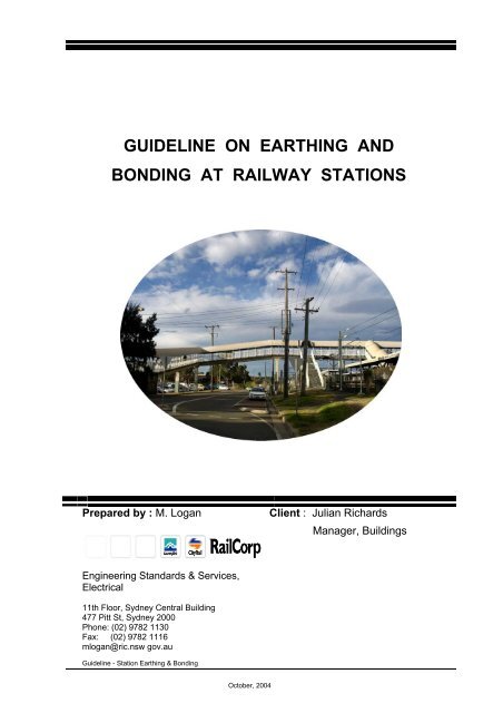
GUIDELINE ON EARTHING AND<br />
BONDING AT RAILWAY STATIONS<br />
Prepared by : M. Logan<br />
Engineering St<strong>and</strong>ards & Services,<br />
Electrical<br />
11th Floor, Sydney Central Building<br />
477 Pitt St, Sydney 2000<br />
Ph<strong>on</strong>e: (02) 9782 1130<br />
Fax: (02) 9782 1116<br />
mlogan@ric.nsw gov.au<br />
<str<strong>on</strong>g>Guideline</str<strong>on</strong>g> - St<strong>at</strong>i<strong>on</strong> <strong>Earthing</strong> & B<strong>on</strong>ding<br />
October, 2004<br />
Client : Julian Richards<br />
Manager, Buildings
Table of c<strong>on</strong>tents<br />
<str<strong>on</strong>g>Guideline</str<strong>on</strong>g> <strong>on</strong> <strong>Earthing</strong> <strong>and</strong> B<strong>on</strong>ding<br />
1. Purpose _______________________________________________________________ 3<br />
2. Scope _________________________________________________________________ 3<br />
3. Introducti<strong>on</strong> ____________________________________________________________ 4<br />
4. Effects of DC Stray Current _______________________________________________ 5<br />
5. <strong>Earthing</strong> <strong>and</strong> B<strong>on</strong>ding Issues ______________________________________________ 6<br />
5.1 B<strong>on</strong>ding ___________________________________________________________________ 6<br />
5.2 <strong>Earthing</strong> __________________________________________________________________ 10<br />
5.3 Separ<strong>at</strong>i<strong>on</strong> issues ___________________________________________________________ 12<br />
5.4 Isol<strong>at</strong>i<strong>on</strong> issues _____________________________________________________________ 20<br />
6. C<strong>on</strong>clusi<strong>on</strong> ____________________________________________________________ 26<br />
APPENDIX 1 _____________________________________________________________ 28<br />
Page 2 of 31
1. Purpose<br />
<str<strong>on</strong>g>Guideline</str<strong>on</strong>g> <strong>on</strong> <strong>Earthing</strong> <strong>and</strong> B<strong>on</strong>ding<br />
The purpose of this document is to promote an awareness of earthing <strong>and</strong><br />
b<strong>on</strong>ding issues prevalent <strong>at</strong> railway st<strong>at</strong>i<strong>on</strong>s. This document has been<br />
produced for internal <strong>RailCorp</strong> use <strong>on</strong>ly. It is particularly targeted for n<strong>on</strong>electrical<br />
pers<strong>on</strong>s such as project managers, asset engineers, external party<br />
works, etc carrying out either c<strong>on</strong>structi<strong>on</strong> or maintenance work <strong>at</strong> railway<br />
st<strong>at</strong>i<strong>on</strong>s.<br />
This document is not intended to be included in any technical brief for<br />
tendering purposes <strong>and</strong> is not a substitute for appropri<strong>at</strong>e engineering<br />
design guidelines.<br />
2. Scope<br />
The overall scope for this guideline targets railway st<strong>at</strong>i<strong>on</strong>s within the<br />
<strong>RailCorp</strong> 1500 volt direct current electrified tracti<strong>on</strong> system.<br />
Specifically, the c<strong>on</strong>tents of this document rel<strong>at</strong>e to the interface of the<br />
tracti<strong>on</strong> 1500V DC tracti<strong>on</strong> system, high voltage reticul<strong>at</strong>i<strong>on</strong> system <strong>and</strong> low<br />
voltage distributi<strong>on</strong> systems. Electrical hazardous situ<strong>at</strong>i<strong>on</strong>s may exist <strong>at</strong><br />
railway st<strong>at</strong>i<strong>on</strong>s due to these interfaces, resulting in issues rel<strong>at</strong>ing to<br />
earthing <strong>and</strong> b<strong>on</strong>ding.<br />
The implic<strong>at</strong>i<strong>on</strong>s for not addressing risk management str<strong>at</strong>egies rel<strong>at</strong>ing to<br />
earthing <strong>and</strong> b<strong>on</strong>ding issues has ramific<strong>at</strong>i<strong>on</strong>s <strong>on</strong> safety <strong>and</strong> infrastructure<br />
integrity, including ec<strong>on</strong>omic <strong>and</strong> oper<strong>at</strong>i<strong>on</strong>al impact.<br />
The outcomes of this guideline are as follows:<br />
• promote an awareness of earthing <strong>and</strong> b<strong>on</strong>ding issues prevalent <strong>at</strong><br />
railway st<strong>at</strong>i<strong>on</strong>s <strong>and</strong> to educ<strong>at</strong>e pers<strong>on</strong>s resp<strong>on</strong>sible for either<br />
c<strong>on</strong>structi<strong>on</strong> or maintenance work <strong>at</strong> railway st<strong>at</strong>i<strong>on</strong>s.<br />
• reduce to a level as low as reas<strong>on</strong>ably practicable the risk of injury<br />
from electric shock from accessible <strong>and</strong> touch voltages.<br />
• reduce to a level as low as reas<strong>on</strong>ably practicable the export of<br />
stray current from DC tracti<strong>on</strong> systems.<br />
Page 3 of 31
3. Introducti<strong>on</strong><br />
<str<strong>on</strong>g>Guideline</str<strong>on</strong>g> <strong>on</strong> <strong>Earthing</strong> <strong>and</strong> B<strong>on</strong>ding<br />
<strong>RailCorp</strong> needs to safeguard itself against risk of damage, fire, electric shock<br />
or loss of life due to risks from faults etc., associ<strong>at</strong>ed with its 1500V DC<br />
tracti<strong>on</strong> system, high voltage reticul<strong>at</strong>i<strong>on</strong> system <strong>and</strong> low voltage distributi<strong>on</strong><br />
systems.<br />
At railway st<strong>at</strong>i<strong>on</strong>s, three main types of risks may exist:<br />
1. Risks associ<strong>at</strong>ed with 1500V DC stray leakage or fault current.<br />
2. Electric shock risk due to 1500V DC touch & step potential rise under<br />
fault c<strong>on</strong>diti<strong>on</strong>, in particular with regard to remote earths in accordance<br />
with EP 00000008SP.<br />
3. Electric shock risk due to high voltage/low voltage distributi<strong>on</strong> systems’<br />
touch & step potential rise under fault c<strong>on</strong>diti<strong>on</strong>, in particular with regard<br />
to different earthing systems.<br />
With the prolifer<strong>at</strong>i<strong>on</strong> of railway st<strong>at</strong>i<strong>on</strong> upgrading work <strong>and</strong> associ<strong>at</strong>ed<br />
c<strong>on</strong>structi<strong>on</strong> of st<strong>at</strong>i<strong>on</strong> canopies, the incidence of electrical hazardous<br />
situ<strong>at</strong>i<strong>on</strong>s has increased. The majority of these situ<strong>at</strong>i<strong>on</strong>s rel<strong>at</strong>e to issues of<br />
earthing <strong>and</strong> b<strong>on</strong>ding.<br />
There is a possibility th<strong>at</strong> overhead wiring structures may rise to a potential<br />
above earth. The risk of pers<strong>on</strong>s receiving an electric shock when st<strong>and</strong>ing<br />
beside an overhead wiring structure <strong>and</strong> touching the structure is present<br />
<strong>and</strong> is of c<strong>on</strong>cern. Other hazardous situ<strong>at</strong>i<strong>on</strong>s where pers<strong>on</strong>s could receive<br />
an electric shock is when physical c<strong>on</strong>tact is made by touching overhead<br />
wiring structures <strong>at</strong> the same time as they touch lighting poles, metallic parts<br />
of canopies or awnings, steel troughing, metal fences or rolling stock.<br />
In order to minimise these risks, methods have been developed <strong>and</strong><br />
deployed for the overhead wiring system which are detailed in RIC<br />
st<strong>and</strong>ards. Selected extracts from relevant RIC documents dealing with<br />
railway st<strong>at</strong>i<strong>on</strong> earthing <strong>and</strong> b<strong>on</strong>ding requirements are in Appendix 1.<br />
One of the more comm<strong>on</strong> c<strong>on</strong>trol measures used <strong>at</strong> st<strong>at</strong>i<strong>on</strong>s is to separ<strong>at</strong>e<br />
overhead wiring structures by distance from any other comp<strong>on</strong>ents <strong>on</strong> the<br />
st<strong>at</strong>i<strong>on</strong>. However, st<strong>at</strong>i<strong>on</strong> upgrading work has often compromised this<br />
c<strong>on</strong>trol, al<strong>on</strong>g with other earthing <strong>and</strong> b<strong>on</strong>ding issues.<br />
Page 4 of 31
4. Effects of DC Stray Current<br />
<str<strong>on</strong>g>Guideline</str<strong>on</strong>g> <strong>on</strong> <strong>Earthing</strong> <strong>and</strong> B<strong>on</strong>ding<br />
DC tracti<strong>on</strong> systems may cause stray currents which could adversely affect<br />
both the railway <strong>and</strong> / or outside interests. The major effects of stray currents<br />
can be:<br />
• corrosi<strong>on</strong> <strong>and</strong> subsequent damage of metallic structures where DC<br />
stray currents leave the metallic structures;<br />
• the risk of overhe<strong>at</strong>ing, arcing <strong>and</strong> fire <strong>and</strong> subsequent danger to<br />
equipment <strong>and</strong> people, both inside <strong>and</strong> outside the rail corridor;<br />
• influence <strong>on</strong> services <strong>and</strong> communic<strong>at</strong>i<strong>on</strong>s systems;<br />
• influence <strong>on</strong> unrel<strong>at</strong>ed c<strong>at</strong>hodic protecti<strong>on</strong> install<strong>at</strong>i<strong>on</strong>s; <strong>and</strong><br />
• influence <strong>on</strong> unrel<strong>at</strong>ed AC <strong>and</strong> DC power supply systems <strong>and</strong> their<br />
associ<strong>at</strong>ed earthing systems.<br />
There are three principal measures available to minimise stray current<br />
emissi<strong>on</strong> from a DC tracti<strong>on</strong> electrific<strong>at</strong>i<strong>on</strong> system:<br />
1. insul<strong>at</strong>i<strong>on</strong> of the tracti<strong>on</strong> return circuit with respect to earth;<br />
2. improvement of the c<strong>on</strong>ductivity of the return circuits; <strong>and</strong><br />
3. design of the tracti<strong>on</strong> power supply system.<br />
In the past, earthing <strong>and</strong> b<strong>on</strong>ding issues have been “designed out” of the rail<br />
system, where possible. However, with the advent of major st<strong>at</strong>i<strong>on</strong><br />
upgrading programs, c<strong>on</strong>siderable problems now exist <strong>at</strong> many st<strong>at</strong>i<strong>on</strong>s<br />
where st<strong>at</strong>i<strong>on</strong> upgrading work has installed canopy awnings <strong>on</strong> pl<strong>at</strong>forms<br />
<strong>and</strong> st<strong>at</strong>i<strong>on</strong> c<strong>on</strong>courses. Typically, many of these projects were “design <strong>and</strong><br />
build” tenders, with the designer not always taking into account the issues<br />
associ<strong>at</strong>ed with earthing <strong>and</strong> b<strong>on</strong>ding.<br />
The problem of minimising stray current is closely rel<strong>at</strong>ed to the problem of<br />
earthing <strong>and</strong>/or b<strong>on</strong>ding of metallic structures to prevent electric shock to<br />
people. The soluti<strong>on</strong>s to both problems often come down to a compromise<br />
since the 'best' soluti<strong>on</strong> for <strong>on</strong>e situ<strong>at</strong>i<strong>on</strong> may result in major problems for the<br />
other issues. However, protective provisi<strong>on</strong>s against electric shock take<br />
precedence over provisi<strong>on</strong>s against the effects of stray current.<br />
Page 5 of 31
5. <strong>Earthing</strong> <strong>and</strong> B<strong>on</strong>ding Issues<br />
<str<strong>on</strong>g>Guideline</str<strong>on</strong>g> <strong>on</strong> <strong>Earthing</strong> <strong>and</strong> B<strong>on</strong>ding<br />
<strong>Earthing</strong> <strong>and</strong> B<strong>on</strong>ding Issues may be c<strong>at</strong>egorised into the following subheadings:<br />
• 1500 Volt B<strong>on</strong>ding<br />
• <strong>Earthing</strong><br />
• Separ<strong>at</strong>i<strong>on</strong> issues<br />
• Isol<strong>at</strong>i<strong>on</strong> issues<br />
More often than not, earthing <strong>and</strong>/or b<strong>on</strong>ding issues are inter-rel<strong>at</strong>ed <strong>and</strong><br />
may involve <strong>on</strong>e or more, or a combin<strong>at</strong>i<strong>on</strong> of the sub-headings.<br />
Many earthing <strong>and</strong> b<strong>on</strong>ding str<strong>at</strong>egies are c<strong>on</strong>diti<strong>on</strong>al up<strong>on</strong> the particular<br />
c<strong>on</strong>figur<strong>at</strong>i<strong>on</strong> of the st<strong>at</strong>i<strong>on</strong> <strong>and</strong> the earthing <strong>and</strong> b<strong>on</strong>ding philosophy adopted<br />
for each unique situ<strong>at</strong>i<strong>on</strong>. In some instances, especially <strong>at</strong> larger complex<br />
st<strong>at</strong>i<strong>on</strong>s, the separ<strong>at</strong>i<strong>on</strong> issues may become too complex <strong>and</strong> too difficult to<br />
adequ<strong>at</strong>ely c<strong>on</strong>trol <strong>and</strong> m<strong>on</strong>itor.<br />
In these situ<strong>at</strong>i<strong>on</strong>s, <strong>on</strong>e opti<strong>on</strong> is to interc<strong>on</strong>nect all metallic structures etc. to<br />
overcome possible touch potential problems, thus neg<strong>at</strong>ing the separ<strong>at</strong>i<strong>on</strong><br />
issues. However, there are also neg<strong>at</strong>ive trade-offs with this opti<strong>on</strong>.<br />
As previously st<strong>at</strong>ed, the resultant soluti<strong>on</strong> to many earthing <strong>and</strong> b<strong>on</strong>ding<br />
issues often come down to a compromise soluti<strong>on</strong>. This especially applies to<br />
c<strong>on</strong>figur<strong>at</strong>i<strong>on</strong>s where these issues have not been adequ<strong>at</strong>ely addressed in<br />
the design stages.<br />
The following headings give a background <strong>on</strong> the outst<strong>and</strong>ing issues rel<strong>at</strong>ing<br />
to each c<strong>at</strong>egory. Descripti<strong>on</strong>s, <strong>and</strong> in some cases photos, are given in each<br />
case to clarify “poor” design c<strong>on</strong>figur<strong>at</strong>i<strong>on</strong>s as opposed to “good” design<br />
c<strong>on</strong>figur<strong>at</strong>i<strong>on</strong>s.<br />
5.1 B<strong>on</strong>ding<br />
Examples of b<strong>on</strong>ding issues are, but are not limited to:<br />
• b<strong>on</strong>ding of steel/metal footbridges (OHW <strong>at</strong>tached)<br />
• b<strong>on</strong>ding of overline traffic bridges (OHW <strong>at</strong>tached)<br />
• b<strong>on</strong>ding of 1500 V structures in vicinity of st<strong>at</strong>i<strong>on</strong> as per st<strong>and</strong>ards<br />
• b<strong>on</strong>ding of safety screens as per st<strong>and</strong>ards<br />
Page 6 of 31
<str<strong>on</strong>g>Guideline</str<strong>on</strong>g> <strong>on</strong> <strong>Earthing</strong> <strong>and</strong> B<strong>on</strong>ding<br />
A number of possible b<strong>on</strong>ding arrangements exist for railway st<strong>at</strong>i<strong>on</strong>s,<br />
depending <strong>on</strong> the c<strong>on</strong>figur<strong>at</strong>i<strong>on</strong> <strong>and</strong> physical arrangement of overhead wiring<br />
supports, the st<strong>at</strong>i<strong>on</strong> premises <strong>and</strong> canopy design.<br />
The b<strong>on</strong>ding arrangements for st<strong>at</strong>i<strong>on</strong>s, st<strong>at</strong>i<strong>on</strong> bridges <strong>and</strong> overline traffic<br />
bridges are covered in documents EP 12 20 00 01 SP “B<strong>on</strong>ding of Overhead<br />
Wiring Structures to Rail” <strong>and</strong> EP 08 00 00 07 SP “Safety Screens for<br />
Bridges over 1500 V OHW Equipment”<br />
There is a possibility th<strong>at</strong> overhead wiring structures may rise to a potential<br />
above earth. The risk of pers<strong>on</strong>s receiving an electric shock when st<strong>and</strong>ing<br />
beside an overhead wiring structure <strong>and</strong> touching the structure is present<br />
<strong>and</strong> is of c<strong>on</strong>cern. Other hazardous situ<strong>at</strong>i<strong>on</strong>s where pers<strong>on</strong>s could receive<br />
an electric shock is when physical c<strong>on</strong>tact is made by touching overhead<br />
wiring structures <strong>at</strong> the same time as they touch lighting poles, metallic parts<br />
of canopies or awnings, steel troughing, metal fences or rolling stock.<br />
In order to minimise this risk, methods have been developed <strong>and</strong> deployed<br />
for the overhead wiring system.<br />
A number of selected OHW structures in the tracti<strong>on</strong> system are required to<br />
be b<strong>on</strong>ded to rail. The determin<strong>at</strong>i<strong>on</strong> of the policy <strong>on</strong> which structures are to<br />
be b<strong>on</strong>ded has involved a risk assessment to identify the most likely<br />
loc<strong>at</strong>i<strong>on</strong>s <strong>and</strong> situ<strong>at</strong>i<strong>on</strong>s giving gre<strong>at</strong>est exposure to risk. As can be seen<br />
from the dot points below, st<strong>at</strong>i<strong>on</strong> pl<strong>at</strong>forms pose the gre<strong>at</strong>est thre<strong>at</strong> of this<br />
risk exposure.<br />
Overhead wiring (OHW) structures, <strong>and</strong> other structures th<strong>at</strong> support 1500V<br />
overhead wiring, <strong>at</strong> prescribed loc<strong>at</strong>i<strong>on</strong>s, must be b<strong>on</strong>ded to a tracti<strong>on</strong> rail<br />
via a spark gap or similar device as detailed in EP 12 20 00 01 SP.<br />
The overhead wiring structures <strong>at</strong> st<strong>at</strong>i<strong>on</strong>s must be b<strong>on</strong>ded to rail as per the<br />
following:<br />
• Where passengers <strong>and</strong>/or the public are likely to c<strong>on</strong>tact the<br />
structure, including OHW structures <strong>at</strong> pl<strong>at</strong>forms <strong>and</strong> up to 10m<br />
bey<strong>on</strong>d the ends of the pl<strong>at</strong>forms.<br />
• Where important structures might otherwise be exposed<br />
excessively to corrosi<strong>on</strong> (e.g. bridges).<br />
Page 7 of 31
<str<strong>on</strong>g>Guideline</str<strong>on</strong>g> <strong>on</strong> <strong>Earthing</strong> <strong>and</strong> B<strong>on</strong>ding<br />
Figure 1 Overhead wiring (OHW) structures, <strong>at</strong> prescribed loc<strong>at</strong>i<strong>on</strong>s, must be b<strong>on</strong>ded<br />
to a tracti<strong>on</strong> rail via a spark gap.<br />
Generally, most smaller st<strong>at</strong>i<strong>on</strong>s in the system are appropri<strong>at</strong>ely b<strong>on</strong>ded <strong>at</strong><br />
overhead wiring structures, foot bridges <strong>and</strong> traffic bridges. Some of the<br />
larger st<strong>at</strong>i<strong>on</strong>s, particularly those th<strong>at</strong> have recently been upgraded, do not<br />
always c<strong>on</strong>form to the required st<strong>and</strong>ards. This situ<strong>at</strong>i<strong>on</strong> has generally<br />
arisen due to the piecemeal approach often adopted by the st<strong>at</strong>i<strong>on</strong><br />
upgrading work over the past decade. The scoping of this work did not<br />
always address the global implic<strong>at</strong>i<strong>on</strong>s of earthing <strong>and</strong> b<strong>on</strong>ding.<br />
At these more complex st<strong>at</strong>i<strong>on</strong>s, some secti<strong>on</strong>s of awning have been built<br />
separ<strong>at</strong>ely but are electrically joined by c<strong>on</strong>ductive elements such as metal<br />
guttering, downpipes, service lines, troughing <strong>and</strong> c<strong>on</strong>duit. This poses a<br />
difficult situ<strong>at</strong>i<strong>on</strong> to segreg<strong>at</strong>e the 1500V circuits from other parts of the<br />
st<strong>at</strong>i<strong>on</strong>. Often the <strong>on</strong>ly opti<strong>on</strong> <strong>at</strong> these st<strong>at</strong>i<strong>on</strong>s is to tre<strong>at</strong> all metallic<br />
structures as <strong>on</strong>e body which would involve the install<strong>at</strong>i<strong>on</strong> of additi<strong>on</strong>al<br />
b<strong>on</strong>ding cables <strong>and</strong> a rec<strong>on</strong>figur<strong>at</strong>i<strong>on</strong> of the existing b<strong>on</strong>ding.<br />
This altern<strong>at</strong>ive, while not necessarily the best opti<strong>on</strong>, is c<strong>on</strong>sidered the most<br />
pragm<strong>at</strong>ic opti<strong>on</strong> for some situ<strong>at</strong>i<strong>on</strong>s due to the numerous pl<strong>at</strong>forms,<br />
stanchi<strong>on</strong>s, service lines, stairs, h<strong>and</strong>rails, canopy supports <strong>and</strong> lighting<br />
columns involved. However, there are neg<strong>at</strong>ive trade-offs with this opti<strong>on</strong><br />
where the sphere of influence is gre<strong>at</strong>ly increased under fault c<strong>on</strong>diti<strong>on</strong>s.<br />
Further, this opti<strong>on</strong> requires engineering analysis <strong>and</strong> b<strong>on</strong>ding design to<br />
ensure the appropri<strong>at</strong>e safety criteria is maintained.<br />
Another safety issue c<strong>on</strong>cerning the proper install<strong>at</strong>i<strong>on</strong> <strong>and</strong> b<strong>on</strong>ding of<br />
structures is the risk of causing a signalling failure due to incorrect<br />
c<strong>on</strong>figur<strong>at</strong>i<strong>on</strong> of spark gap b<strong>on</strong>ds. This safety issue highlights the need for a<br />
proper detailed design approach, especially for larger complex st<strong>at</strong>i<strong>on</strong>s.<br />
Page 8 of 31
<str<strong>on</strong>g>Guideline</str<strong>on</strong>g> <strong>on</strong> <strong>Earthing</strong> <strong>and</strong> B<strong>on</strong>ding<br />
EP 08 00 00 07 SP document sets out the design, c<strong>on</strong>structi<strong>on</strong> <strong>and</strong> b<strong>on</strong>ding<br />
requirements for safety screens <strong>on</strong> bridges <strong>and</strong> other structures loc<strong>at</strong>ed<br />
above or beside exposed 1500 V dc equipment.<br />
There are instances where no b<strong>on</strong>ding is present <strong>on</strong> safety screens where it<br />
is required, (as shown in figures 2 & 3) <strong>and</strong> there are instances where the<br />
methodology of the b<strong>on</strong>ding c<strong>on</strong>necti<strong>on</strong>s is inc<strong>on</strong>sistent.<br />
Figure 2 Safety screen associ<strong>at</strong>ed with a c<strong>on</strong>crete footbridge where b<strong>on</strong>ding is required<br />
Figure 3 Note the insul<strong>at</strong>i<strong>on</strong> between the metal safety screens <strong>and</strong> the c<strong>on</strong>crete bridge in<br />
accordance with <strong>RailCorp</strong> st<strong>and</strong>ards<br />
Electrical insul<strong>at</strong>i<strong>on</strong> between the metal safety screens <strong>and</strong> the c<strong>on</strong>crete<br />
reinforcement associ<strong>at</strong>ed with the c<strong>on</strong>crete bridges must be present.<br />
Further details are given in the Civil Design Drawing 160-801 “Electrical<br />
Safety Screens”.<br />
Another issue is the prolifer<strong>at</strong>i<strong>on</strong> of Anti-Throw Barriers (Anti-Projectile<br />
Screens) which are increasingly being installed <strong>on</strong> Overbridges. These<br />
metal screens can have major implic<strong>at</strong>i<strong>on</strong>s to the existing b<strong>on</strong>ding<br />
Page 9 of 31
<str<strong>on</strong>g>Guideline</str<strong>on</strong>g> <strong>on</strong> <strong>Earthing</strong> <strong>and</strong> B<strong>on</strong>ding<br />
arrangements <strong>at</strong> Overbridges. These install<strong>at</strong>i<strong>on</strong>s need to be assessed <strong>on</strong> a<br />
case by case basis for earthing <strong>and</strong> b<strong>on</strong>ding determin<strong>at</strong>i<strong>on</strong>.<br />
5.2 <strong>Earthing</strong><br />
Examples of earthing issues are, but are not limited to:<br />
• direct earthing system - isol<strong>at</strong>i<strong>on</strong> transformers<br />
• main earthing c<strong>on</strong>ductor (earth bar to footbridge) minimum 16mm 2<br />
• overbridge having low voltage cables in c<strong>on</strong>tact with the bridge<br />
c<strong>on</strong>nected to a 6 m electrode<br />
• main earthing c<strong>on</strong>ductor (footbridge to earth electrode) 70mm 2<br />
• interface between <strong>RailCorp</strong>’s supply earth <strong>and</strong> other Network<br />
Oper<strong>at</strong>or supply earth<br />
• issue of canopies under transmissi<strong>on</strong> lines<br />
<strong>Railway</strong> st<strong>at</strong>i<strong>on</strong>s in the electrified area employ a “direct earthing system”.<br />
This system is applicable to electrical supplies sourced from either<br />
<strong>RailCorp</strong>’s electrical system or altern<strong>at</strong>ive Supply Authorities. In more recent<br />
years, many st<strong>at</strong>i<strong>on</strong> supplies have been transferred from <strong>RailCorp</strong>’s<br />
electrical system to altern<strong>at</strong>ive supplies from either Energy Australia or<br />
Integral Energy. The situ<strong>at</strong>i<strong>on</strong> has been exacerb<strong>at</strong>ed with the requirement of<br />
three phase supplies for lifts installed <strong>at</strong> st<strong>at</strong>i<strong>on</strong>s under the Easy Access<br />
Programme. Under these circumstances, an isol<strong>at</strong>ing transformer is<br />
required to separ<strong>at</strong>e the st<strong>at</strong>i<strong>on</strong> earthing from the Supply Authority's earthing<br />
system. The isol<strong>at</strong>ing transformer is c<strong>on</strong>nected between the local Electricity<br />
Distributor's service equipment <strong>and</strong> the supply main switchboard to<br />
physically isol<strong>at</strong>e the earth <strong>and</strong> neutral of the MEN supply from any part of<br />
<strong>RailCorp</strong>’s distributi<strong>on</strong> system, including earthed metalwork (such as pipes,<br />
fences, overhead earth wires or troughing).<br />
Any maintenance work or upgrading work must be m<strong>on</strong>itored to ensure the<br />
interface c<strong>on</strong>diti<strong>on</strong>s are not compromised. Isol<strong>at</strong>ing transformers can be<br />
effectively bypassed due to interc<strong>on</strong>necti<strong>on</strong>s of the earthing systems via<br />
canopies or bus/rail interchanges. Electrical supply from different sources,<br />
for example lighting, can inadvertently bridge the earthing systems.<br />
All Isol<strong>at</strong>ing Transformers must comply with RIC specific<strong>at</strong>i<strong>on</strong> EP 17 00 00<br />
11 SP “Low Voltage Isol<strong>at</strong>ing Transformers”. In particular, <strong>at</strong>tenti<strong>on</strong> is drawn<br />
to the namepl<strong>at</strong>e requirements to readily ascertain compliance to the<br />
required specific<strong>at</strong>i<strong>on</strong>.<br />
Page 10 of 31
<str<strong>on</strong>g>Guideline</str<strong>on</strong>g> <strong>on</strong> <strong>Earthing</strong> <strong>and</strong> B<strong>on</strong>ding<br />
When loadings <strong>at</strong> st<strong>at</strong>i<strong>on</strong>s are substantially increased, corresp<strong>on</strong>ding higher<br />
fault levels are present. The earthing systems <strong>at</strong> st<strong>at</strong>i<strong>on</strong>s may require<br />
upgrading in line with additi<strong>on</strong>al loadings. The assessment of the suitability<br />
<strong>and</strong> integrity of the existing earthing system must form part of any upgrading<br />
work.<br />
Sometimes the main earth electrode is not visible <strong>at</strong> st<strong>at</strong>i<strong>on</strong>s, posing major<br />
problems for <strong>on</strong>going maintenance <strong>and</strong> testing. This problem has often<br />
occurred due to the covering over of the st<strong>at</strong>i<strong>on</strong> earth electrodes during<br />
st<strong>at</strong>i<strong>on</strong> upgrading work.<br />
Figure 4 St<strong>at</strong>i<strong>on</strong> main earth electrode is comm<strong>on</strong>ly housed in a c<strong>on</strong>crete<br />
housing as shown. Note also the insul<strong>at</strong>ed w<strong>at</strong>er mains.<br />
Documents EP 12 10 00 20 SP “Low Voltage Distributi<strong>on</strong> <strong>Earthing</strong>” <strong>and</strong> EP<br />
12 00 00 02 SP “Low Voltage Distributi<strong>on</strong> <strong>and</strong> Install<strong>at</strong>i<strong>on</strong>s <strong>Earthing</strong><br />
References <strong>and</strong> Definiti<strong>on</strong>s” lists the public<strong>at</strong>i<strong>on</strong>s <strong>and</strong> drawings relevant to<br />
earthing arrangements <strong>and</strong> other associ<strong>at</strong>ed inform<strong>at</strong>i<strong>on</strong>.<br />
Another pressing issue in rel<strong>at</strong>i<strong>on</strong> to earthing <strong>and</strong> st<strong>at</strong>i<strong>on</strong> upgrading is the<br />
hazard associ<strong>at</strong>ed with many of the new canopies loc<strong>at</strong>ed under high<br />
voltage transmissi<strong>on</strong> lines. There is a safety risk to oper<strong>at</strong>i<strong>on</strong>al pers<strong>on</strong>nel or<br />
members of the public which arises from the danger of direct c<strong>on</strong>tact with a<br />
fallen overhead transmissi<strong>on</strong> line or indirect c<strong>on</strong>tact with touch voltages th<strong>at</strong><br />
may arise under fault c<strong>on</strong>diti<strong>on</strong>s.<br />
It is good policy not to build new canopies, buildings or other frequented<br />
structures under high voltage transmissi<strong>on</strong> lines. Document EP 12 10 00 22<br />
SP “Buildings <strong>and</strong> Structures Under Overhead Lines” provides further details<br />
<strong>on</strong> this issue.<br />
Page 11 of 31
<str<strong>on</strong>g>Guideline</str<strong>on</strong>g> <strong>on</strong> <strong>Earthing</strong> <strong>and</strong> B<strong>on</strong>ding<br />
Figure 5 Avoid building new canopies, buildings or other frequented<br />
structures under high voltage transmissi<strong>on</strong> lines<br />
This issue of structures loc<strong>at</strong>ed under high voltage transmissi<strong>on</strong> lines is<br />
currently being reviewed by <strong>RailCorp</strong>.<br />
5.3 Separ<strong>at</strong>i<strong>on</strong> issues<br />
Examples of separ<strong>at</strong>i<strong>on</strong> issues are, but are not limited to:<br />
• metallic structures are physically separ<strong>at</strong>ed by <strong>at</strong> least 2 metres<br />
distance from OHW structures<br />
• canopy supports to be <strong>at</strong> least 2 metres from OHW structures<br />
• lighting st<strong>and</strong>ards to be <strong>at</strong> least 2 metres from OHW structures<br />
• lineside fencing to be <strong>at</strong> least 2 metres from OHW structures<br />
• vending machines to be <strong>at</strong> least 2 metres from OHW structures<br />
• ticketing machines to be <strong>at</strong> least 2 metres from OHW structures<br />
• teleph<strong>on</strong>e booths to be <strong>at</strong> least 2 metres from OHW structures<br />
There is a possibility th<strong>at</strong> overhead wiring structures may rise to a potential<br />
above earth. A pers<strong>on</strong> could receive an electric shock when physical<br />
c<strong>on</strong>tact is made by touching overhead wiring structures <strong>at</strong> the same time as<br />
they touch lighting poles, metallic parts of canopies or awnings, steel<br />
troughing, metal fences or rolling stock.<br />
The majority of the st<strong>at</strong>i<strong>on</strong>s in the Metropolitan area adopt the policy of<br />
separ<strong>at</strong>i<strong>on</strong> of the overhead wiring structures from other structures such as<br />
Page 12 of 31
<str<strong>on</strong>g>Guideline</str<strong>on</strong>g> <strong>on</strong> <strong>Earthing</strong> <strong>and</strong> B<strong>on</strong>ding<br />
roofs <strong>and</strong> buildings. Being in the vicinity of the general public, these OHW<br />
structures are normally spark gapped to rail in accordance with RIC policy<br />
document EP 12 20 00 01 SP “B<strong>on</strong>ding of Overhead Wiring Structures to<br />
Rail”. In doing so, any oper<strong>at</strong>i<strong>on</strong> of the spark gap results in the structure<br />
being directly c<strong>on</strong>nected to rail with the resultant structure having a voltage<br />
present corresp<strong>on</strong>ding to the rail voltage. The rail voltage level is dependent<br />
up<strong>on</strong> many factors such as loc<strong>at</strong>i<strong>on</strong>, distance from the subst<strong>at</strong>i<strong>on</strong>, train<br />
loadings <strong>and</strong> the characteristics of the rail <strong>and</strong> the overhead wiring. Under<br />
certain circumstances, this voltage can rise to potentially dangerous levels.<br />
However, the upper voltage limits are overseen by the rail earth c<strong>on</strong>tactor <strong>at</strong><br />
Subst<strong>at</strong>i<strong>on</strong> <strong>and</strong> Secti<strong>on</strong>ing Huts.<br />
Problems can exist <strong>on</strong> st<strong>at</strong>i<strong>on</strong>s due to b<strong>on</strong>ding arrangements of the<br />
overhead wiring structures. The most comm<strong>on</strong> problems are proximity of<br />
the overhead wiring structures to:<br />
1. metal fencing,<br />
2. metallic awning supports,<br />
3. earthed metallic objects such as lighting st<strong>and</strong>ards, vending<br />
machines, w<strong>at</strong>er pipes, teleph<strong>on</strong>e booths, fire hydrant appar<strong>at</strong>us <strong>and</strong><br />
CCTV's.<br />
For situ<strong>at</strong>i<strong>on</strong>s where any of the separ<strong>at</strong>i<strong>on</strong> criteria cannot be achieved,<br />
altern<strong>at</strong>ive opti<strong>on</strong>s may be implemented to neg<strong>at</strong>e the separ<strong>at</strong>i<strong>on</strong> issue.<br />
Briefly, the possible altern<strong>at</strong>ive arrangements are:<br />
1. Reloc<strong>at</strong>i<strong>on</strong><br />
The best electrical soluti<strong>on</strong>, although not the most ec<strong>on</strong>omical<br />
soluti<strong>on</strong>, is to reloc<strong>at</strong>e all offending metallic supports to comply with<br />
the 2 metre rule of separ<strong>at</strong>i<strong>on</strong> of two differing potentials.<br />
Page 13 of 31
Figure 6 Opti<strong>on</strong> 1 - Metallic supports<br />
to comply with the 2 metre rule of<br />
separ<strong>at</strong>i<strong>on</strong> from OHW structure.<br />
2. Limited Isol<strong>at</strong>i<strong>on</strong><br />
<str<strong>on</strong>g>Guideline</str<strong>on</strong>g> <strong>on</strong> <strong>Earthing</strong> <strong>and</strong> B<strong>on</strong>ding<br />
Figure 7 Opti<strong>on</strong> 4 - OHW structure isol<strong>at</strong>i<strong>on</strong><br />
where the OHW stucture is enclosed by<br />
insul<strong>at</strong>i<strong>on</strong> m<strong>at</strong>erial.<br />
This opti<strong>on</strong> <strong>at</strong>tempts to limit the physical extent of c<strong>on</strong>ductive<br />
m<strong>at</strong>erial which could be exposed to 1500 V fault current by<br />
segreg<strong>at</strong>i<strong>on</strong> using appropri<strong>at</strong>e insul<strong>at</strong>ed secti<strong>on</strong>s to ensure<br />
electrical disc<strong>on</strong>tinuity.<br />
This opti<strong>on</strong> has significant maintenance issues.<br />
3. Interc<strong>on</strong>nected metal mass.<br />
This opti<strong>on</strong> <strong>at</strong>tempts to overcome possible touch potential problems<br />
by ensuring all metallic structures are electrically c<strong>on</strong>nected.<br />
However, this opti<strong>on</strong> can have neg<strong>at</strong>ive trade-offs. 1500V fault<br />
current will have a wider area of influence <strong>and</strong> the resulting fault<br />
current p<strong>at</strong>h will be difficult to predict <strong>and</strong> manage.<br />
4. OHW structure isol<strong>at</strong>i<strong>on</strong><br />
This opti<strong>on</strong> uses the c<strong>on</strong>cept of double insul<strong>at</strong>i<strong>on</strong> to effectively<br />
isol<strong>at</strong>e an OHW structure secti<strong>on</strong> from the remaining secti<strong>on</strong>s of<br />
the structure.<br />
This opti<strong>on</strong> has significant cost impacts as well as <strong>on</strong>going<br />
maintenance <strong>and</strong> surveillance issues.<br />
The best opti<strong>on</strong> which overcomes the majority of earthing <strong>and</strong> b<strong>on</strong>ding<br />
issues is opti<strong>on</strong> 1, which uses the principle of separ<strong>at</strong>i<strong>on</strong>. Obviously, in<br />
install<strong>at</strong>i<strong>on</strong>s where this separ<strong>at</strong>i<strong>on</strong> is compromised, it can be an expensive<br />
exercise to either reloc<strong>at</strong>e all offending metallic supports or revert to other<br />
altern<strong>at</strong>ives.<br />
Page 14 of 31
<str<strong>on</strong>g>Guideline</str<strong>on</strong>g> <strong>on</strong> <strong>Earthing</strong> <strong>and</strong> B<strong>on</strong>ding<br />
It is stressed th<strong>at</strong> the most cost effective <strong>and</strong> safest c<strong>on</strong>figur<strong>at</strong>i<strong>on</strong> for any<br />
new canopy or building work is to incorpor<strong>at</strong>e the principle of separ<strong>at</strong>i<strong>on</strong> into<br />
the design stage. If earthing <strong>and</strong> b<strong>on</strong>ding issues are integr<strong>at</strong>ed into the<br />
design stage, substantial cost savings can be achieved as well as drastically<br />
reducing the risk exposure to pers<strong>on</strong>s <strong>and</strong> property.<br />
This process of “designing out” earthing <strong>and</strong> b<strong>on</strong>ding issues must be an<br />
essential outcome for <strong>RailCorp</strong> to safeguard itself against risk of damage,<br />
fire, electric shock or loss of life.<br />
Figure 8 Example of poor design where the new canopy supports are in close proximity to<br />
the existing OHW structure.<br />
Many st<strong>at</strong>i<strong>on</strong>s suffer from the problem of close proximity of overhead wiring<br />
structures to fencing. The typical fencing encountered <strong>on</strong> many st<strong>at</strong>i<strong>on</strong>s is<br />
the powder co<strong>at</strong>ed pool style fencing which can run al<strong>on</strong>g either a secti<strong>on</strong> of<br />
the st<strong>at</strong>i<strong>on</strong> pl<strong>at</strong>form or the total length of the pl<strong>at</strong>form.<br />
Page 15 of 31
Figure 9 Close proximity of fencing <strong>and</strong><br />
lighting st<strong>and</strong>ard to the overhead wiring<br />
structure. Note the CCTV metal<br />
c<strong>on</strong>duit <strong>at</strong> bottom of fence bridging any<br />
isol<strong>at</strong>i<strong>on</strong> gaps if present.<br />
<str<strong>on</strong>g>Guideline</str<strong>on</strong>g> <strong>on</strong> <strong>Earthing</strong> <strong>and</strong> B<strong>on</strong>ding<br />
Figure 10 Correctly installed fencing with two<br />
separ<strong>at</strong>e isol<strong>at</strong>i<strong>on</strong> gaps placed <strong>at</strong> least two metres <strong>on</strong><br />
either side of the OHW structure.<br />
On some st<strong>at</strong>i<strong>on</strong>s, the fencing has been properly installed by cre<strong>at</strong>ing two<br />
separ<strong>at</strong>e isol<strong>at</strong>i<strong>on</strong> gaps placed <strong>at</strong> least two metres <strong>on</strong> either side of the OHW<br />
structure as shown in Figure 10. However, there are many instances where<br />
c<strong>on</strong>tractors have bridged these gaps with metal c<strong>on</strong>duit, usually used in the<br />
install<strong>at</strong>i<strong>on</strong> of extra lighting, w<strong>at</strong>er pipes or CCTV's. The appropri<strong>at</strong>e remedy<br />
for such situ<strong>at</strong>i<strong>on</strong>s is the replacement of the metal comp<strong>on</strong>ent across the<br />
gap with a n<strong>on</strong>-c<strong>on</strong>ducting enclosure with suitable mechanical protecti<strong>on</strong>.<br />
C<strong>on</strong>siderable problems exist <strong>at</strong> many st<strong>at</strong>i<strong>on</strong>s where st<strong>at</strong>i<strong>on</strong> upgrading work<br />
has installed canopy awnings <strong>on</strong> pl<strong>at</strong>forms <strong>and</strong> st<strong>at</strong>i<strong>on</strong> c<strong>on</strong>courses.<br />
Typically, many of these projects were design <strong>and</strong> build tenders, with the<br />
designer not always taking into account the separ<strong>at</strong>i<strong>on</strong> issues associ<strong>at</strong>ed<br />
with earthing <strong>and</strong> b<strong>on</strong>ding. C<strong>on</strong>sequently, large amounts of c<strong>on</strong>tingency<br />
work have been required over the last few years to correct many of the<br />
problems <strong>at</strong> st<strong>at</strong>i<strong>on</strong>s. The most comm<strong>on</strong> problem is the close proximity of<br />
metallic awning supports rel<strong>at</strong>ive to overhead wiring structures where<br />
metallic awning supports are within the two metre separ<strong>at</strong>i<strong>on</strong> distances.<br />
Page 16 of 31
<str<strong>on</strong>g>Guideline</str<strong>on</strong>g> <strong>on</strong> <strong>Earthing</strong> <strong>and</strong> B<strong>on</strong>ding<br />
Figure 11 Awning supports within 2 metres of OHW structures.<br />
This situ<strong>at</strong>i<strong>on</strong> poses a potential voltage difference between the two<br />
structures <strong>and</strong> is a safety risk to oper<strong>at</strong>i<strong>on</strong>al pers<strong>on</strong>nel or members of the<br />
public.<br />
Another problem <strong>at</strong> st<strong>at</strong>i<strong>on</strong>s is where an overhead wiring structure protrudes<br />
through the roof without sufficient clearance from the structure to the roofing.<br />
A gap of <strong>at</strong> least 50 millimetres is required to ensure electrical separ<strong>at</strong>i<strong>on</strong> of<br />
the two structures, otherwise arcing can occur in the event of a spark gap<br />
failure. At a number of loc<strong>at</strong>i<strong>on</strong>s, the install<strong>at</strong>i<strong>on</strong> of n<strong>on</strong>-insul<strong>at</strong>ing flashing<br />
has occurred to elimin<strong>at</strong>e the ingress of rain, thus bridging the gap <strong>and</strong><br />
cre<strong>at</strong>ing an undesirable current p<strong>at</strong>h.<br />
Figure 12 Overhead wiring structure<br />
protruding through the roof without sufficient<br />
clearance<br />
Figure 13 Example of unacceptable install<strong>at</strong>i<strong>on</strong><br />
using n<strong>on</strong>-insul<strong>at</strong>ing flashing.<br />
Page 17 of 31
<str<strong>on</strong>g>Guideline</str<strong>on</strong>g> <strong>on</strong> <strong>Earthing</strong> <strong>and</strong> B<strong>on</strong>ding<br />
This situ<strong>at</strong>i<strong>on</strong> is unacceptable. If the spark gap blows, the tracti<strong>on</strong> return<br />
current would flow through the metal roof <strong>and</strong> in turn flow through the low<br />
voltage lighting circuit with the possibility of an electrical fire <strong>and</strong> resultant<br />
coll<strong>at</strong>eral damage to the st<strong>at</strong>i<strong>on</strong>.<br />
This situ<strong>at</strong>i<strong>on</strong> can be corrected by ensuring a gap of <strong>at</strong> least 50mm<br />
surrounding each structure. If required, the resultant gap could be filled in<br />
by insul<strong>at</strong>ed sheet flashing such as polycarb<strong>on</strong><strong>at</strong>e to seal against the<br />
we<strong>at</strong>her.<br />
Figure 14 Example of acceptable<br />
arrangement showing insul<strong>at</strong>ed sheet<br />
flashing <strong>and</strong> surrounding gap to the OHW<br />
structure.<br />
Figure 15 Example where roofing m<strong>at</strong>erial is<br />
in direct c<strong>on</strong>tact with the overhead wiring<br />
structure<br />
Another comm<strong>on</strong> problem is where roofing renewal has occurred <strong>and</strong> either<br />
the roofing supports or the roofing m<strong>at</strong>erial are in direct c<strong>on</strong>tact with the<br />
overhead wiring structure. This situ<strong>at</strong>i<strong>on</strong> is unacceptable, as shown in Figure<br />
15.<br />
Page 18 of 31
Figure 16 OHW structure in close proximity to vending machines<br />
<str<strong>on</strong>g>Guideline</str<strong>on</strong>g> <strong>on</strong> <strong>Earthing</strong> <strong>and</strong> B<strong>on</strong>ding<br />
A touch potential problem can exists where the OHW structure is in close<br />
proximity to vending machines.<br />
The arrangement <strong>at</strong> Figure 16 presents vending machines <strong>at</strong> low voltage<br />
earth potential within 2 metres of the OHW structure. Pers<strong>on</strong>s could bridge<br />
themselves between these two c<strong>on</strong>ductive comp<strong>on</strong>ents <strong>at</strong> differing potential.<br />
To remedy this situ<strong>at</strong>i<strong>on</strong>, the vending machines should be reloc<strong>at</strong>ed <strong>at</strong> least<br />
2 metres away from the structure.<br />
Touch potential problems can also exist where the stanchi<strong>on</strong> is in close<br />
proximity to a Telstra ph<strong>on</strong>e booth.<br />
Page 19 of 31
Figure 17 OHW structure in close proximity to<br />
Telstra ph<strong>on</strong>e booth<br />
<str<strong>on</strong>g>Guideline</str<strong>on</strong>g> <strong>on</strong> <strong>Earthing</strong> <strong>and</strong> B<strong>on</strong>ding<br />
Figure 18 Unistrut in c<strong>on</strong>tact with the canopy<br />
support <strong>and</strong> the fire hydrant service pipe<br />
This arrangement presents the ph<strong>on</strong>e booth <strong>at</strong> low voltage earth potential<br />
th<strong>at</strong> is within 2 metres of the stanchi<strong>on</strong>. Pers<strong>on</strong>s could bridge themselves<br />
between these two c<strong>on</strong>ductive comp<strong>on</strong>ents <strong>at</strong> differing potential.<br />
5.4 Isol<strong>at</strong>i<strong>on</strong> issues<br />
Examples of isol<strong>at</strong>i<strong>on</strong> issues are, but are not limited to:<br />
• isol<strong>at</strong>i<strong>on</strong> of boundary fence to st<strong>at</strong>i<strong>on</strong> fencing<br />
• signalling troughing – appropri<strong>at</strong>e insul<strong>at</strong>ed secti<strong>on</strong>s<br />
• isol<strong>at</strong>i<strong>on</strong> of all incoming metallic service lines - w<strong>at</strong>er, gas, fire<br />
service, teleph<strong>on</strong>e, sewerage, stormw<strong>at</strong>er/downpipe etc<br />
• any introduced electrical supplies - isol<strong>at</strong>i<strong>on</strong> transformers<br />
• any interface between <strong>RailCorp</strong>’s supply <strong>and</strong> other Network<br />
Oper<strong>at</strong>or supply<br />
Page 20 of 31
<str<strong>on</strong>g>Guideline</str<strong>on</strong>g> <strong>on</strong> <strong>Earthing</strong> <strong>and</strong> B<strong>on</strong>ding<br />
• CCTV implic<strong>at</strong>i<strong>on</strong>s: metallic c<strong>on</strong>duit runs, video cable c<strong>on</strong>necti<strong>on</strong>s<br />
Document EP 12 10 00 21 SP “Low Voltage Install<strong>at</strong>i<strong>on</strong>s <strong>Earthing</strong>” details<br />
the earthing <strong>and</strong> b<strong>on</strong>ding requirements of various types of low voltage<br />
install<strong>at</strong>i<strong>on</strong>s loc<strong>at</strong>ed <strong>on</strong> the `railway corridor' <strong>and</strong> `near 1500 V track'.<br />
Where a railway st<strong>at</strong>i<strong>on</strong> interfaces with another building or structure, such as<br />
a bus rail interchange or a footbridge th<strong>at</strong> c<strong>on</strong>nects a railway st<strong>at</strong>i<strong>on</strong> with a<br />
shopping centre, the design shall not allow the extensi<strong>on</strong> of <strong>RailCorp</strong>’s low<br />
voltage earthing system bey<strong>on</strong>d the railway corridor. This includes all<br />
metallic structures <strong>and</strong> services, such as awnings, fences, pipes <strong>and</strong><br />
electrical wiring <strong>and</strong> c<strong>on</strong>duits. The interface should be well defined <strong>and</strong><br />
easily observable. This is usually achieved by installing two isol<strong>at</strong>i<strong>on</strong> 'gaps' in<br />
the steelwork, about 2m apart.<br />
Figure 19 Example of a footbridge th<strong>at</strong> c<strong>on</strong>nects a railway st<strong>at</strong>i<strong>on</strong>. The design shall not allow<br />
the extensi<strong>on</strong> of <strong>RailCorp</strong>’s low voltage earthing system bey<strong>on</strong>d the railway corridor<br />
Problems occur where isol<strong>at</strong>i<strong>on</strong> points have been bridged by either c<strong>on</strong>duits<br />
or other circuits. Situ<strong>at</strong>i<strong>on</strong>s have occurred where the install<strong>at</strong>i<strong>on</strong> of the CCTV<br />
has bridged out the isol<strong>at</strong>ing secti<strong>on</strong>s separ<strong>at</strong>ing the st<strong>at</strong>i<strong>on</strong> supply from<br />
another separ<strong>at</strong>e Supply Authority supply, such as a st<strong>at</strong>i<strong>on</strong> car park. These<br />
situ<strong>at</strong>i<strong>on</strong>s require c<strong>on</strong>stant surveillance to ensure the isol<strong>at</strong>i<strong>on</strong> is not<br />
compromised. Too often c<strong>on</strong>tractors <strong>and</strong> other associ<strong>at</strong>ed parties<br />
performing work <strong>on</strong> st<strong>at</strong>i<strong>on</strong>s are not aware of these issues.<br />
Page 21 of 31
<str<strong>on</strong>g>Guideline</str<strong>on</strong>g> <strong>on</strong> <strong>Earthing</strong> <strong>and</strong> B<strong>on</strong>ding<br />
Figure 20 Example where the isol<strong>at</strong>i<strong>on</strong> point between two secti<strong>on</strong>s of canopy has been<br />
bridged by modified guttering.<br />
Bus/rail interchange situ<strong>at</strong>i<strong>on</strong>s often require major modific<strong>at</strong>i<strong>on</strong>s to canopies<br />
<strong>and</strong> roofing to overcome the isol<strong>at</strong>i<strong>on</strong> problems. These post-c<strong>on</strong>structi<strong>on</strong><br />
modific<strong>at</strong>i<strong>on</strong>s <strong>and</strong> associ<strong>at</strong>ed major expenses could be minimised if the<br />
designs for st<strong>at</strong>i<strong>on</strong> upgrading were scrutinised prior to c<strong>on</strong>structi<strong>on</strong> to<br />
capture any potential problems. Many st<strong>at</strong>i<strong>on</strong>s have been compromised<br />
where the best technical soluti<strong>on</strong> has not been able to be implemented due<br />
to the major modific<strong>at</strong>i<strong>on</strong>s <strong>and</strong> costs involved. Instead a less desirable<br />
altern<strong>at</strong>ive to overcome touch potential issues has had to be implemented <strong>at</strong><br />
certain loc<strong>at</strong>i<strong>on</strong>s.<br />
In additi<strong>on</strong>, due to the interacti<strong>on</strong> of the low voltage electrical supply to<br />
st<strong>at</strong>i<strong>on</strong>s (ie light fittings associ<strong>at</strong>ed with awnings or canopies) <strong>and</strong> the<br />
proximity of 1500 V overhead wiring structures, special analysis for each<br />
st<strong>at</strong>i<strong>on</strong> is required to minimise the risk of electric shock <strong>and</strong> also comb<strong>at</strong> the<br />
effects of electrolysis associ<strong>at</strong>ed with a DC tracti<strong>on</strong> system.<br />
Another comm<strong>on</strong> problem effecting st<strong>at</strong>i<strong>on</strong>s is the inter c<strong>on</strong>necti<strong>on</strong> of the<br />
<strong>Railway</strong> boundary fence to st<strong>at</strong>i<strong>on</strong> fencing. This situ<strong>at</strong>i<strong>on</strong> can c<strong>on</strong>tribute to<br />
the electrolysis problems associ<strong>at</strong>ed with the tracti<strong>on</strong> system. On many<br />
st<strong>at</strong>i<strong>on</strong>s, additi<strong>on</strong>al metallic fencing panels <strong>and</strong> fencing wire have been<br />
added <strong>at</strong> the ends of pl<strong>at</strong>forms to prohibit illegal access.<br />
Page 22 of 31
<str<strong>on</strong>g>Guideline</str<strong>on</strong>g> <strong>on</strong> <strong>Earthing</strong> <strong>and</strong> B<strong>on</strong>ding<br />
Figure 21 Example showing inter-c<strong>on</strong>necti<strong>on</strong> of the <strong>Railway</strong> boundary fence to st<strong>at</strong>i<strong>on</strong> fencing<br />
Again, isol<strong>at</strong>i<strong>on</strong> secti<strong>on</strong>s should be installed <strong>at</strong> the fencing interface or <strong>at</strong> an<br />
appropri<strong>at</strong>e loc<strong>at</strong>i<strong>on</strong> in close proximity to the st<strong>at</strong>i<strong>on</strong>. These fencing issues<br />
are canvassed in document C 4501”Metallic Lineside Fencing in Electrified<br />
Areas”.<br />
Additi<strong>on</strong>ally, appropri<strong>at</strong>e insul<strong>at</strong>ed secti<strong>on</strong>s must exist for metal signalling<br />
troughing, in accordance with RIC st<strong>and</strong>ards.<br />
Another issue becoming more prevalent is the install<strong>at</strong>i<strong>on</strong> of metal coping<br />
edges al<strong>on</strong>g st<strong>at</strong>i<strong>on</strong> pl<strong>at</strong>forms. Depending <strong>on</strong> the install<strong>at</strong>i<strong>on</strong> method, this<br />
c<strong>on</strong>figur<strong>at</strong>i<strong>on</strong> can have earthing <strong>and</strong> b<strong>on</strong>ding issues, especially where<br />
appropri<strong>at</strong>e isol<strong>at</strong>i<strong>on</strong> is not present. Instances have been reported (Circular<br />
Quay) where severe arcing has taken place when wheel chair accessibility<br />
ramps have been placed <strong>on</strong> the pl<strong>at</strong>form where metal coping exists.<br />
A major c<strong>on</strong>cern is the seemingly omissi<strong>on</strong> of isol<strong>at</strong>i<strong>on</strong> joints for incoming<br />
metallic service lines <strong>on</strong>to the rail corridor. These isol<strong>at</strong>i<strong>on</strong> joints are<br />
essential to ensure the segreg<strong>at</strong>i<strong>on</strong> of the railway earthing to the service<br />
lines to minimise the affects of electrolysis. Isol<strong>at</strong>i<strong>on</strong> joints for services such<br />
as gas, w<strong>at</strong>er, fire services, etc. must be visible for inspecti<strong>on</strong> <strong>and</strong>/or have<br />
appropri<strong>at</strong>e signage in accordance with RIC st<strong>and</strong>ards, including. EP 12 30<br />
00 01 SP “Electrolysis From Stray DC Current”.<br />
Page 23 of 31
<str<strong>on</strong>g>Guideline</str<strong>on</strong>g> <strong>on</strong> <strong>Earthing</strong> <strong>and</strong> B<strong>on</strong>ding<br />
Figure 22 . Isol<strong>at</strong>i<strong>on</strong> joints for services such as gas, w<strong>at</strong>er, fire services, etc. must be visible<br />
for inspecti<strong>on</strong> <strong>and</strong>/or have appropri<strong>at</strong>e signage.<br />
Another major issue coming to the fore is the prolifer<strong>at</strong>i<strong>on</strong> of CCTV cameras<br />
<strong>on</strong> st<strong>at</strong>i<strong>on</strong>s which has the potential to cause fire <strong>and</strong> coll<strong>at</strong>eral damage.<br />
Figure 23 Black flexible metal c<strong>on</strong>duit bridging the two structures which<br />
are designed to be electrically separ<strong>at</strong>ed<br />
Incidences have occurred where the metal c<strong>on</strong>duit housing the coax cable<br />
for the CCTV's has breached separ<strong>at</strong>e secti<strong>on</strong>s of canopies causing the<br />
cable to melt, resulting in a roof fire eg. Epping St<strong>at</strong>i<strong>on</strong>.<br />
Page 24 of 31
<str<strong>on</strong>g>Guideline</str<strong>on</strong>g> <strong>on</strong> <strong>Earthing</strong> <strong>and</strong> B<strong>on</strong>ding<br />
Figure 24 Example where CCTV metallic c<strong>on</strong>duit has bridged out isol<strong>at</strong>i<strong>on</strong> secti<strong>on</strong>s.<br />
Often, the CCTV install<strong>at</strong>i<strong>on</strong> has compromised the isol<strong>at</strong>i<strong>on</strong> requirements <strong>on</strong><br />
st<strong>at</strong>i<strong>on</strong>s where metallic c<strong>on</strong>duit has bridged out isol<strong>at</strong>i<strong>on</strong> secti<strong>on</strong>s. Some<br />
initial discussi<strong>on</strong>s <strong>on</strong> these m<strong>at</strong>ters have been held with St<strong>at</strong>e Rail <strong>on</strong><br />
install<strong>at</strong>i<strong>on</strong> methods required <strong>at</strong> st<strong>at</strong>i<strong>on</strong>s.<br />
Page 25 of 31
6. C<strong>on</strong>clusi<strong>on</strong><br />
<str<strong>on</strong>g>Guideline</str<strong>on</strong>g> <strong>on</strong> <strong>Earthing</strong> <strong>and</strong> B<strong>on</strong>ding<br />
<strong>Earthing</strong> <strong>and</strong> b<strong>on</strong>ding issues <strong>at</strong> railway st<strong>at</strong>i<strong>on</strong>s are predominantly <strong>at</strong>tributed<br />
to the interface issues between overhead wiring structures, awnings or<br />
canopies <strong>and</strong> services entering the rail corridor.<br />
The most comm<strong>on</strong> problems are rel<strong>at</strong>ed to the b<strong>on</strong>ding arrangements<br />
associ<strong>at</strong>ed with overhead wiring structures in close proximity to:<br />
• metallic awning supports,<br />
• metal fencing,<br />
• earthed metallic objects such as lighting st<strong>and</strong>ards, vending<br />
machines, w<strong>at</strong>er pipes, teleph<strong>on</strong>e booths, fire hydrant appar<strong>at</strong>us<br />
<strong>and</strong> CCTV's.<br />
Generally, most st<strong>at</strong>i<strong>on</strong>s in the electrified system are appropri<strong>at</strong>ely b<strong>on</strong>ded <strong>at</strong><br />
overhead wiring structures, foot bridges <strong>and</strong> traffic bridges. Spark gaps are<br />
an essential safety device <strong>and</strong> are critical to the 1500V tracti<strong>on</strong> system<br />
protecti<strong>on</strong> <strong>and</strong> b<strong>on</strong>ding scheme. As such, any maintenance or c<strong>on</strong>structi<strong>on</strong><br />
work involving these items should be carried out in accordance to <strong>RailCorp</strong>’s<br />
policy requirements.<br />
Another comm<strong>on</strong> problem effecting st<strong>at</strong>i<strong>on</strong>s is the interface of the railway<br />
boundary fence to st<strong>at</strong>i<strong>on</strong> fencing. This situ<strong>at</strong>i<strong>on</strong> can c<strong>on</strong>tribute to the<br />
effects of electrolysis. Some of these defects are <strong>at</strong>tributable to additi<strong>on</strong>al<br />
metallic fencing panels <strong>and</strong> fencing wire installed to prohibit illegal access <strong>at</strong><br />
the ends of pl<strong>at</strong>forms <strong>and</strong> the lack of an isol<strong>at</strong>ing panel or isol<strong>at</strong>i<strong>on</strong> secti<strong>on</strong>s<br />
of fencing.<br />
Many st<strong>at</strong>i<strong>on</strong>s have situ<strong>at</strong>i<strong>on</strong>s where interface issues between <strong>RailCorp</strong>’s<br />
supply earth <strong>and</strong> another Network Oper<strong>at</strong>or supply earth apply. At these<br />
loc<strong>at</strong>i<strong>on</strong>s, any maintenance work or upgrading work must be m<strong>on</strong>itored to<br />
ensure the interface c<strong>on</strong>diti<strong>on</strong>s are not compromised. It is recommended<br />
th<strong>at</strong> appropri<strong>at</strong>e signage would be beneficial to alert c<strong>on</strong>tractors <strong>and</strong> other<br />
pers<strong>on</strong>nel to this issue. Additi<strong>on</strong>allly, install<strong>at</strong>i<strong>on</strong> of radi<strong>at</strong>ing services such<br />
as CCTV must be carefully designed <strong>and</strong> c<strong>on</strong>trolled to ensure isol<strong>at</strong>i<strong>on</strong><br />
secti<strong>on</strong>s are not bridged.<br />
Issues such as high voltage transmissi<strong>on</strong> lines sited above secti<strong>on</strong>s of<br />
st<strong>at</strong>i<strong>on</strong> canopies or roof areas must also be m<strong>on</strong>itored when planning any<br />
upgrading work.<br />
Another safety issue c<strong>on</strong>cerning the proper install<strong>at</strong>i<strong>on</strong> <strong>and</strong> b<strong>on</strong>ding of<br />
structures is the risk of causing a signalling failure due to incorrect<br />
c<strong>on</strong>figur<strong>at</strong>i<strong>on</strong> of spark gap b<strong>on</strong>ds. This safety issue highlights the need for a<br />
proper detailed design approach, especially for larger complex st<strong>at</strong>i<strong>on</strong>s.<br />
Page 26 of 31
<str<strong>on</strong>g>Guideline</str<strong>on</strong>g> <strong>on</strong> <strong>Earthing</strong> <strong>and</strong> B<strong>on</strong>ding<br />
The siting of services <strong>on</strong> st<strong>at</strong>i<strong>on</strong>s such as vending machines, ticketing<br />
machines, teleph<strong>on</strong>e booths, w<strong>at</strong>er taps, etc must be c<strong>on</strong>sidered in rel<strong>at</strong>i<strong>on</strong><br />
to earthing <strong>and</strong> b<strong>on</strong>ding principles.<br />
With the further roll out of st<strong>at</strong>i<strong>on</strong> upgrading projects, the issues associ<strong>at</strong>ed<br />
with railway st<strong>at</strong>i<strong>on</strong> interfaces with other buildings, structures, bus-rail<br />
interchanges etc will become more prevalent. Gre<strong>at</strong>er c<strong>on</strong>trol over this work<br />
is crucial to ensure <strong>RailCorp</strong>’s st<strong>and</strong>ards are met in future.<br />
Past deficiencies in rel<strong>at</strong>i<strong>on</strong> to earthing <strong>and</strong> b<strong>on</strong>ding are due to the<br />
piecemeal approach often adopted by the st<strong>at</strong>i<strong>on</strong> upgrading work. Projects<br />
must not limit their scope to their own upgrading work without addressing the<br />
global implic<strong>at</strong>i<strong>on</strong>s of earthing <strong>and</strong> b<strong>on</strong>ding.<br />
At more complex st<strong>at</strong>i<strong>on</strong>s, some c<strong>on</strong>figur<strong>at</strong>i<strong>on</strong>s pose a difficult situ<strong>at</strong>i<strong>on</strong> to<br />
segreg<strong>at</strong>e the 1500V circuits from other parts of the st<strong>at</strong>i<strong>on</strong>. Often the best<br />
compromise opti<strong>on</strong> <strong>at</strong> these st<strong>at</strong>i<strong>on</strong>s is to tre<strong>at</strong> all metallic structures as <strong>on</strong>e<br />
body. This altern<strong>at</strong>ive, while not necessarily the optimal opti<strong>on</strong>, is c<strong>on</strong>sidered<br />
the most pragm<strong>at</strong>ic opti<strong>on</strong> for some situ<strong>at</strong>i<strong>on</strong>s due to the numerous<br />
pl<strong>at</strong>forms, stanchi<strong>on</strong>s, service lines, stairs, h<strong>and</strong>rails, canopy supports <strong>and</strong><br />
lighting columns involved. However, there are neg<strong>at</strong>ive trade-offs with this<br />
opti<strong>on</strong> where the sphere of influence is gre<strong>at</strong>ly increased under fault<br />
c<strong>on</strong>diti<strong>on</strong>s. Further, this opti<strong>on</strong> requires engineering analysis <strong>and</strong> b<strong>on</strong>ding<br />
design to ensure the appropri<strong>at</strong>e safety criteria is maintained.<br />
It is emphasised th<strong>at</strong> appropri<strong>at</strong>e c<strong>on</strong>figur<strong>at</strong>i<strong>on</strong> document<strong>at</strong>i<strong>on</strong> for earthing,<br />
b<strong>on</strong>ding <strong>and</strong> electrolysis mitig<strong>at</strong>i<strong>on</strong> equipment is essential to minimise the<br />
risks associ<strong>at</strong>ed with these issues. This c<strong>on</strong>figur<strong>at</strong>i<strong>on</strong> document<strong>at</strong>i<strong>on</strong> must<br />
be incorpor<strong>at</strong>ed into any new project involving upgrading work to ensure<br />
integrity of the assets <strong>and</strong> allow for maintainability.<br />
It is evident th<strong>at</strong> there is no simple formula for solving existing problems,<br />
especially <strong>at</strong> more complex st<strong>at</strong>i<strong>on</strong>s. In these situ<strong>at</strong>i<strong>on</strong>s, each st<strong>at</strong>i<strong>on</strong> must<br />
be assessed <strong>on</strong> its own merit, taking into c<strong>on</strong>sider<strong>at</strong>i<strong>on</strong> the existing<br />
c<strong>on</strong>figur<strong>at</strong>i<strong>on</strong> <strong>and</strong> the proposed work to determine the best optimal soluti<strong>on</strong>,<br />
culmin<strong>at</strong>ing in the producti<strong>on</strong> of an earthing <strong>and</strong> b<strong>on</strong>ding design.<br />
The principle of separ<strong>at</strong>i<strong>on</strong> is the best opti<strong>on</strong> th<strong>at</strong> overcomes the majority of<br />
earthing <strong>and</strong> b<strong>on</strong>ding issues, especially for limited new work. Obviously, in<br />
existing install<strong>at</strong>i<strong>on</strong>s where this separ<strong>at</strong>i<strong>on</strong> is already compromised, it can be<br />
an expensive exercise to either reloc<strong>at</strong>e all offending metallic supports or<br />
revert to other altern<strong>at</strong>ives.<br />
From a risk management perspective, the process of “designing out”<br />
earthing <strong>and</strong> b<strong>on</strong>ding issues must be the first choice in the hierarchy of<br />
managing these risks. This is especially so in rel<strong>at</strong>i<strong>on</strong> to proposed new<br />
upgrading work.<br />
It is stressed th<strong>at</strong> the most cost effective <strong>and</strong> safest c<strong>on</strong>figur<strong>at</strong>i<strong>on</strong> for any<br />
new canopy or building work is to incorpor<strong>at</strong>e the principle of separ<strong>at</strong>i<strong>on</strong>, if<br />
feasible, into the design stage. If earthing <strong>and</strong> b<strong>on</strong>ding issues are integr<strong>at</strong>ed<br />
into the design stage, substantial cost savings can be achieved as well as<br />
drastically reducing the risk exposure to pers<strong>on</strong>s, property <strong>and</strong> <strong>RailCorp</strong>.<br />
Page 27 of 31
APPENDIX 1<br />
<str<strong>on</strong>g>Guideline</str<strong>on</strong>g> <strong>on</strong> <strong>Earthing</strong> <strong>and</strong> B<strong>on</strong>ding<br />
The following are selected extracts from relevant RIC (<strong>RailCorp</strong>) documents dealing<br />
with railway st<strong>at</strong>i<strong>on</strong> earthing <strong>and</strong> b<strong>on</strong>ding requirements. The extracts are not a<br />
comprehensive set of document<strong>at</strong>i<strong>on</strong> but have been compiled to c<strong>on</strong>cisely highlight<br />
the major issues associ<strong>at</strong>ed with earthing <strong>and</strong> b<strong>on</strong>ding.<br />
EP 12 10 00 21 SP<br />
Low Voltage Install<strong>at</strong>i<strong>on</strong>s <strong>Earthing</strong><br />
1.1. Clearances from 1500 V Structures <strong>and</strong> Other Earthed Metalwork<br />
A 2 m distance shall be maintained between the earthing system of the low voltage<br />
install<strong>at</strong>i<strong>on</strong>, including earthed metalwork for example fences, vending machines <strong>and</strong><br />
teleph<strong>on</strong>e cabinets, <strong>and</strong> any overhead wiring structures which are not b<strong>on</strong>ded to the<br />
same earthing system or metalwork c<strong>on</strong>nected to a separ<strong>at</strong>e earthing system.<br />
1.6. Lineside Metal Fencing or Signal Troughing<br />
A 2 m clearance must be maintained between any metal c<strong>on</strong>nected to the railway<br />
st<strong>at</strong>i<strong>on</strong>s low voltage earth <strong>and</strong> any c<strong>on</strong>tinuous metal structure, such as a fence or<br />
signal troughing, th<strong>at</strong> is not intenti<strong>on</strong>ally c<strong>on</strong>nected to the earthing system. Where the<br />
2 m clearance cannot be obtained, a suitable approved method such as installing two<br />
isol<strong>at</strong>ing breaks 2 m apart in the c<strong>on</strong>tinuous metal structure shall be used.<br />
Altern<strong>at</strong>ively the situ<strong>at</strong>i<strong>on</strong> can be proved safe by calcul<strong>at</strong>i<strong>on</strong> <strong>and</strong> testing for dangerous<br />
touch voltages in accordance with the ESAA Subst<strong>at</strong>i<strong>on</strong> <strong>Earthing</strong> Guide.<br />
1.7. Metallic C<strong>on</strong>duits<br />
In general metallic c<strong>on</strong>duits are not permitted to be installed underground or in<br />
c<strong>on</strong>crete within the electrified area due to the presence of stray 1500 V dc leakage<br />
currents. However, in practice short lengths should not present a problem, therefore, if<br />
a situ<strong>at</strong>i<strong>on</strong> arises where a short length of buried metallic c<strong>on</strong>duit is the preferred<br />
method then the definiti<strong>on</strong> of appreciable dc leakage current from Specific<strong>at</strong>i<strong>on</strong><br />
EP12000002SP - "Low Voltage Distributi<strong>on</strong> <strong>and</strong> Install<strong>at</strong>i<strong>on</strong>s <strong>Earthing</strong> References <strong>and</strong><br />
Definiti<strong>on</strong>s" can be applied<br />
2. Overbridge having 1500 V Overhead Wiring <strong>and</strong> Low Voltage Wiring<br />
Attached<br />
2.1. C<strong>on</strong>necti<strong>on</strong> to Electrode<br />
An overbridge <strong>at</strong> any railway st<strong>at</strong>i<strong>on</strong> in the electrified area having low voltage cables in<br />
c<strong>on</strong>tact with the bridge will require the bridge to be c<strong>on</strong>nected to a 6 m electrode using<br />
a 70 mm² copper c<strong>on</strong>ductor, refer to secti<strong>on</strong> 2.1.1. The electrode is to be loc<strong>at</strong>ed as<br />
close as possible to the bridge <strong>and</strong> installed as detailed in secti<strong>on</strong>s 2.1.2 <strong>and</strong> 2.1.3.<br />
The 70 mm² c<strong>on</strong>ductor shall be protected against mechanical damage as detailed in<br />
Page 28 of 31
<str<strong>on</strong>g>Guideline</str<strong>on</strong>g> <strong>on</strong> <strong>Earthing</strong> <strong>and</strong> B<strong>on</strong>ding<br />
secti<strong>on</strong> 1.5 <strong>and</strong> be secured to the over bridge by no lesser security than a crimped<br />
closed lug, lock-nutted <strong>on</strong>to a stud of minimum size 12 mm.<br />
3. <strong>Railway</strong> St<strong>at</strong>i<strong>on</strong> Interfaces<br />
Where a railway st<strong>at</strong>i<strong>on</strong> adjoins with another building or structure, such as a bus rail<br />
interchange or a footbridge th<strong>at</strong> c<strong>on</strong>nects a railway st<strong>at</strong>i<strong>on</strong> with a shopping centre, the<br />
design shall not allow the extensi<strong>on</strong> of the RIC low voltage earthing system bey<strong>on</strong>d<br />
the railway corridor. This includes all metallic structures <strong>and</strong> services, such as<br />
awnings, fences, pipes <strong>and</strong> electrical wiring <strong>and</strong> c<strong>on</strong>duits. The interface should be well<br />
defined <strong>and</strong> easily observable <strong>and</strong> where any doubt exists the situ<strong>at</strong>i<strong>on</strong> shall be<br />
proved safe by calcul<strong>at</strong>i<strong>on</strong> <strong>and</strong> testing for dangerous touch voltages in accordance<br />
with the ESAA Subst<strong>at</strong>i<strong>on</strong> <strong>Earthing</strong> Guide.<br />
The metalwork of the structure th<strong>at</strong> has been isol<strong>at</strong>ed from the st<strong>at</strong>i<strong>on</strong> may be<br />
c<strong>on</strong>nected to an MEN earthing system.<br />
C 4501<br />
Metallic Lineside Fencing in Electrified Areas<br />
When c<strong>on</strong>structing metallic fencing al<strong>on</strong>g the 1500V DC electrified rail corridor, the<br />
following key electrical aspects must be c<strong>on</strong>sidered:<br />
• The transfer of touch <strong>and</strong> step potentials al<strong>on</strong>g the metallic fencing, <strong>and</strong><br />
• The mitig<strong>at</strong>i<strong>on</strong> of electrolysis.<br />
EP 12 30 00 01 SP<br />
Electrolysis From Stray DC Current<br />
1 Introducti<strong>on</strong><br />
….Ideally, all current should return through the rails, but since they are in close<br />
c<strong>on</strong>tact with the ground through the sleepers <strong>and</strong> ballast, some current will 'leak' from<br />
the rails <strong>and</strong> return to the subst<strong>at</strong>i<strong>on</strong> through the ground. This is called 'stray current'<br />
or 'leakage current'…..<br />
…..The problem of minimising electrolysis is closely rel<strong>at</strong>ed to the problem of earthing<br />
<strong>and</strong>/or b<strong>on</strong>ding of metallic structures to prevent electric shock to people. The soluti<strong>on</strong>s<br />
to both problems have to be a compromise since the 'best' soluti<strong>on</strong> for <strong>on</strong>e situ<strong>at</strong>i<strong>on</strong><br />
results in major problems for the other situ<strong>at</strong>i<strong>on</strong>.<br />
5 Minimis<strong>at</strong>i<strong>on</strong> Techniques<br />
The following minimis<strong>at</strong>i<strong>on</strong> techniques are recommended for any pers<strong>on</strong> engaging in<br />
work within the `railway corridor' <strong>and</strong> near `1500 V track'. All m<strong>and</strong><strong>at</strong>ory requirements<br />
are covered in relevant documents.<br />
• Overhead wiring structures which are b<strong>on</strong>ded to rail via a spark gap do not c<strong>on</strong>tact<br />
earthed services such as st<strong>at</strong>i<strong>on</strong> awnings, fences, w<strong>at</strong>er pipes etc.<br />
Page 29 of 31
<str<strong>on</strong>g>Guideline</str<strong>on</strong>g> <strong>on</strong> <strong>Earthing</strong> <strong>and</strong> B<strong>on</strong>ding<br />
• In tunnels, <strong>on</strong> bridges <strong>and</strong> under air-space developments, there is no c<strong>on</strong>tact<br />
between rails <strong>and</strong> reinforcing or other steelwork.<br />
• Keep metallic services 'away' from the track so there is less chance of 'picking up'<br />
appreciable dc leakage current.<br />
• All low voltage supplies use Isol<strong>at</strong>ing transformers. Local Electricity Distributor<br />
neutral <strong>and</strong> earthing systems should not enter <strong>Railway</strong> Corridor.<br />
• W<strong>at</strong>er <strong>and</strong> Gas pipes servicing buildings <strong>on</strong> the <strong>Railway</strong> Corridor <strong>and</strong> near 1500 V<br />
track to have an isol<strong>at</strong>ing joint installed <strong>at</strong> the boundary.<br />
• Fencing <strong>at</strong> st<strong>at</strong>i<strong>on</strong>s <strong>and</strong> electrical subst<strong>at</strong>i<strong>on</strong>s is not to be c<strong>on</strong>nected to the lineside<br />
fencing.<br />
• Ensure all metallic structures such as footbridges, bus shelters etc. are isol<strong>at</strong>ed <strong>at</strong><br />
boundary of <strong>Railway</strong> Corridor. This is usually achieved by installing two 'gaps' in<br />
the steelwork, about 2m apart. Special care is needed if there is lighting installed,<br />
to ensure the local Electricity Distributor's earth is not c<strong>on</strong>nected to the steelwork<br />
which forms part of any overhead wiring structure, st<strong>at</strong>i<strong>on</strong> or bridge.<br />
EP 12 10 00 22 SP<br />
Buildings <strong>and</strong> Structures Under Overhead Lines<br />
1. High Voltage Transmissi<strong>on</strong> Lines<br />
Where a building or structure is loc<strong>at</strong>ed such th<strong>at</strong> possible risks could arise due to<br />
inducti<strong>on</strong>, touch or step voltages, infringement of safety clearances to c<strong>on</strong>ductors, or<br />
the failure of line m<strong>at</strong>erials or structures, the earthing system of the building or<br />
structure shall meet the requirements of the Electricity Council of NSW document EC<br />
20 - "<str<strong>on</strong>g>Guideline</str<strong>on</strong>g>s for the Management of Electricity Easements".<br />
EP 12 00 00 02 SP<br />
Low Voltage Distributi<strong>on</strong> <strong>and</strong> Install<strong>at</strong>i<strong>on</strong>s <strong>Earthing</strong><br />
References <strong>and</strong> Definiti<strong>on</strong>s<br />
This document lists the public<strong>at</strong>i<strong>on</strong>s <strong>and</strong> drawings th<strong>at</strong> are referenced in associ<strong>at</strong>ed<br />
documents <strong>and</strong> can provide extra background inform<strong>at</strong>i<strong>on</strong>.<br />
EP 12 10 00 20 SP<br />
Low Voltage Distributi<strong>on</strong> <strong>Earthing</strong><br />
2. Supply from Local Electricity Distributor's Network<br />
2.1. General<br />
Page 30 of 31
<str<strong>on</strong>g>Guideline</str<strong>on</strong>g> <strong>on</strong> <strong>Earthing</strong> <strong>and</strong> B<strong>on</strong>ding<br />
The MEN system of a local Electricity Distributor must not be allowed to pick up<br />
appreciable dc leakage current. The recognised method of achieving this is to ensure<br />
the earth <strong>and</strong> neutral of the MEN supply is physically isol<strong>at</strong>ed from any part of the<br />
supplied install<strong>at</strong>i<strong>on</strong>, including earthed metalwork (such as pipes, fences, overhead<br />
earth wires or troughing).<br />
This document is based <strong>on</strong> the use of an isol<strong>at</strong>ing transformer to separ<strong>at</strong>e the local<br />
Electricity Distributor's MEN earth <strong>and</strong> neutral from the RIC distributi<strong>on</strong> systems direct<br />
earthing system……..<br />
2.3. Isol<strong>at</strong>ing Transformer<br />
An isol<strong>at</strong>ing transformer shall be c<strong>on</strong>nected between the local Electricity Distributor's<br />
service equipment <strong>and</strong> the supply main switchboard to physically isol<strong>at</strong>e the earth <strong>and</strong><br />
neutral of the MEN supply from any part of the RIC distributi<strong>on</strong> system, including<br />
earthed metalwork (such as pipes, fences, overhead earth wires or troughing).<br />
The isol<strong>at</strong>ing transformer shall comply with SRA Specific<strong>at</strong>i<strong>on</strong> A-844 (now RIC<br />
specific<strong>at</strong>i<strong>on</strong> EP 17 00 00 11 SP). The transformer shall be installed with a sign<br />
prominently displayed <strong>on</strong> its case st<strong>at</strong>ing th<strong>at</strong> it is double insul<strong>at</strong>ed <strong>and</strong> c<strong>on</strong>forms to<br />
AS 3108……….<br />
Page 31 of 31