N123-138 Series Snap Trac Dither Generator and ... - Moog Inc
N123-138 Series Snap Trac Dither Generator and ... - Moog Inc
N123-138 Series Snap Trac Dither Generator and ... - Moog Inc

You also want an ePaper? Increase the reach of your titles
YUMPU automatically turns print PDFs into web optimized ePapers that Google loves.
SPECIFICATIONS<br />
<strong>Dither</strong> <strong>Generator</strong><br />
Square wave at terminal 2.<br />
Triangular wave at terminal 6.<br />
Frequency ≈ 400 Hz.<br />
Frequency range of 0.05 to 1000 Hz<br />
can be obtained by changing R9<br />
<strong>and</strong>/or C3 (20KΩ to 10MΩ <strong>and</strong><br />
0.01µF to 5µF).<br />
freq =<br />
1 ( –––––––) Hz<br />
4•R9•C3<br />
Amplitude ≈ 16 volts peak-to-peak<br />
(each waveform).<br />
See servovalve catalog for<br />
recommended dither amplitude <strong>and</strong><br />
frequency.<br />
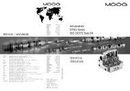
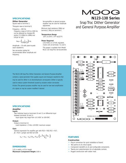
The <strong>N123</strong>-<strong>138</strong> <strong>Snap</strong> <strong>Trac</strong> <strong>Dither</strong> <strong>Generator</strong> <strong>and</strong> General Purpose Amplifier<br />
contains a signal generator that supplies square <strong>and</strong> triangular waveforms that<br />
may be used for dither in an electrohydraulic servosystem. <strong>Dither</strong> is typically<br />
used to reduce system threshold caused by actuator <strong>and</strong>/or servovalve<br />
friction.The general purpose amplifier may be used for low level amplification<br />
of a signal, or may be custom modified if desired.<br />
SPECIFICATIONS<br />
Servoamplifier or general purpose<br />
amplifier may be used for amplitude<br />
adjustment.<br />
Minimum load resistance: 20KΩ on<br />
terminal 2; 5KΩ on terminal 6.<br />
Temperature Range:<br />
-20°C to 50°C (-4°F to122°F)<br />
Power Required:<br />
±15.0 VDC at ±17mA, regulated,<br />
3-wire (±E) at terminals 7, 8, <strong>and</strong> 9.<br />
This power is available from Model<br />
N121-132 <strong>Snap</strong> <strong>Trac</strong> Servocontroller.<br />
Amplifier<br />
Inputs:<br />
Two individual inputs at terminals 10 <strong>and</strong> 11; or differential input<br />
between terminals 10 <strong>and</strong> 11.<br />
Input signals may range from ±0.1 VDC to 100 VDC.<br />
Output:<br />
Output at terminal 12.<br />
Load impedance ≥ 5 KΩ. ±10 VDC maximum output.<br />
Gain:<br />
General expression for amplifier gain with R16 = R18, R15 = R17,<br />
J6 = R19 = Jumper <strong>and</strong> R25 full CW:<br />
R24 + R25 e12 = (e11 - e10) (R16 / R15) ( 1+ –––––––––)<br />
R23 DIMENSIONS<br />
3.25 in width x 4.70 in length<br />
Maximum Component Height: 0.69 in<br />
1 2 3 4 5 6 7 8 9 10 11 12 13 14<br />
<strong>N123</strong>-<strong>138</strong> <strong>Series</strong><br />
<strong>Snap</strong> <strong>Trac</strong> <strong>Dither</strong> <strong>Generator</strong><br />
<strong>and</strong> General Purpose Amplifier<br />
TP1<br />
R7<br />
R30<br />
EXT EXT<br />
P1<br />
PIN14<br />
INT INT<br />
PIN13<br />
J1<br />
J2<br />
J3<br />
TP2<br />
C1<br />
C2<br />
R6<br />
R4<br />
R5<br />
R8<br />
R10<br />
R9<br />
R11<br />
R17<br />
R15<br />
R16<br />
R29<br />
COMMON<br />
TP3<br />
C4<br />
R19<br />
MODEL:<strong>N123</strong>-<strong>138</strong><br />
SN:<br />
TP8<br />
A1<br />
D1<br />
D2<br />
R12<br />
R13<br />
R18<br />
A2<br />
R20<br />
TP12<br />
C3<br />
CW R25<br />
FEATURES<br />
Construction<br />
➢ Plug-in connectors for quick installation of board.<br />
➢ Test points on all critical signals.<br />
➢ Component st<strong>and</strong>offs on all user-configurable components.<br />
➢ Twenty-turn potentiometers for all adjustable controls.<br />
➢ Rugged construction with solder mask.<br />
R28<br />
R2<br />
R1<br />
R14<br />
R27<br />
R22<br />
R24<br />
R26<br />
R23<br />
R21<br />
TP6<br />
R3<br />
GAIN
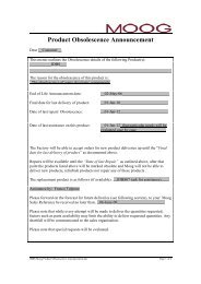
<strong>N123</strong>-<strong>138</strong> DITHER GENERATOR AND GENERAL PURPOSE AMPLIFIER<br />
INPUT SIGNAL<br />
0 TO +15.0 VDC<br />
SIGNAL GROUND<br />
SEE NOTE 5<br />
UNUSED INPUT<br />
INPUT SIGNAL<br />
0 TO -15.O VDC<br />
SINGLE<br />
INPUT SIGNAL<br />
INDIVIDUAL INPUTS OR<br />
DIFFERENTIAL INPUT<br />
CIRCUITRY<br />
<strong>Dither</strong> <strong>Generator</strong><br />
The dither generator consists of a<br />
comparator stage (A1A), amplitude<br />
limiting stages (A1C/D2 <strong>and</strong> A1D/D1)<br />
<strong>and</strong> an integrating amplifier stage<br />
(A1B). Upon startup,A1A will attempt<br />
to go to + or - saturation. However,<br />
the peak voltage will be limited to<br />
approximately ±8 VDC by D1/A1D or<br />
D2/A1C.A1B ramps up or down, as<br />
the case may be, until the output<br />
voltage is sufficient to cause the<br />
feedback voltage at the comparator<br />
(through voltage divider R8, R11) to<br />
change polarity.At this point,A1A<br />
switches polarity <strong>and</strong> A1B begins to<br />
ramp in the opposite direction.<br />
+E<br />
7<br />
5<br />
R2<br />
R1<br />
NF<br />
CW<br />
R3<br />
+E<br />
+AMPLITUDE LIMIT<br />
SIGNAL GROUND<br />
C1<br />
10uF<br />
C2<br />
10uF<br />
TP8<br />
8<br />
POWER<br />
INPUTS<br />
(REGULATED)<br />
49.9K<br />
49.9K<br />
POWER<br />
INPUTS<br />
-E<br />
9<br />
TP3<br />
+E<br />
(REGULATED)<br />
TP2<br />
3<br />
J2 INT<br />
EXT<br />
12 4<br />
13<br />
A1D<br />
14<br />
TL084CN<br />
11<br />
-E<br />
D1<br />
2<br />
SQUARE<br />
WAVE<br />
OUTPUT<br />
SIGNAL<br />
5<br />
COMPARATOR<br />
R6<br />
TYPICAL STANDOFF<br />
INTEGRATOR<br />
NF<br />
C3<br />
-E<br />
0.01uF<br />
TP6<br />
4 X<br />
R30<br />
0<br />
R4<br />
24.9K<br />
R5<br />
100K<br />
2<br />
3<br />
11<br />
A1A<br />
1<br />
TL084CN<br />
4<br />
+E<br />
R7<br />
2K<br />
R8<br />
49.9K<br />
R9<br />
61.9K R10<br />
49.9K<br />
6<br />
5<br />
-E<br />
11<br />
7<br />
A1B<br />
TL084CN<br />
4<br />
+E<br />
R11<br />
49.9K<br />
6<br />
TRIANGULAR WAVE<br />
OUTPUT SIGNAL<br />
-E<br />
1<br />
J1<br />
EXT<br />
INT<br />
TP1<br />
9 11<br />
8<br />
10 A1C<br />
TL084CN<br />
4<br />
D2<br />
GENERAL PURPOSE AMP<br />
+E -AMPLITUDE LIMIT<br />
R21<br />
R22<br />
R12<br />
R13<br />
10K<br />
NF<br />
(TEST POINT)<br />
TP12<br />
49.9K 49.9K<br />
6<br />
R19 5<br />
5<br />
R14 CW<br />
NF<br />
-E<br />
+E<br />
0<br />
R20<br />
NF<br />
7<br />
6 A2B<br />
TL082CP<br />
12<br />
GAIN<br />
13<br />
R27<br />
NF<br />
6 R26<br />
NF<br />
R24<br />
10K<br />
R25<br />
CW<br />
100K<br />
11<br />
R15<br />
100K<br />
DIFFERENTIAL AMP<br />
R16<br />
100K<br />
+E<br />
R28<br />
0<br />
TL082CP<br />
CW<br />
-E<br />
BIAS<br />
R23<br />
10K<br />
6<br />
OUTPUT SIGNAL<br />
10<br />
R17<br />
100K<br />
3<br />
2<br />
8<br />
A2A<br />
4<br />
R29<br />
0<br />
R18 -E<br />
1<br />
J3<br />
PIN 13<br />
PIN 14<br />
14<br />
100K<br />
NOTES:<br />
C4<br />
NF<br />
1. NF = NOT FURNISHED<br />
2. ■ = PIN 1 (SQUARE PIN)<br />
3. = INDICATES COMPONENT MOUNTED ON STANDOFFS<br />
4. CW = CLOCKWISE<br />
General Purpose Amplifier<br />
A differential input amplifier (A2A)<br />
<strong>and</strong> a non-inverting amplifier (A2B)<br />
are mounted on this board for<br />
general signal amplification. Input<br />
signals are applied to terminal 10<br />
<strong>and</strong> 11, with the output signal at<br />
terminal 12.Amplification of each<br />
stage should be between 0.1 <strong>and</strong> 10<br />
volts/volt with resistor values between<br />
10KΩ <strong>and</strong> 100 KΩ.<br />
SPECIAL MODIFICATIONS / SET-UP / OPTIONS<br />
Refer to section on set-up instructions <strong>and</strong> technical information for additional<br />
assistance on card usage <strong>and</strong> application. R1, R14, R27, R26, R24, R19 sizing<br />
options are located in set-up instruction section of literature.<br />
5 DO NOT CONNECT DC SIGNAL TO PIN-4. REFER TO SET-UP<br />
INSTRUCTION SECTION FOR ADDITIONAL INFORMATION.<br />
6 REFER TO “SPECIAL MODIFICATION” OPTIONS<br />
ADJUSTMENTS<br />
Gain (R25) – provides 12:2<br />
amplification range of A2B.<br />
Bias (R27) – not furnished.<br />
(Recommended size is 100K)<br />
MOUNTING:<br />
Mount using Curtiss type TR-3<br />
plastic track (<strong>Moog</strong> P/N 65419-1)
SET-UP INSTRUCTIONS<br />
The card is factory built to supply a<br />
<strong>Dither</strong> Frequency of Approx. 400Hz<br />
Calculated Outputs<br />
➢Determine required <strong>Dither</strong><br />
frequency needed<br />
➢Calculate <strong>Dither</strong> Frequency ➡<br />
f DITHER = [1 / (4xR9xC3)]Hz (using<br />
Triangle waveform)<br />
➢Refer to Servovalve Catalog for<br />
recommended dither amplitude &<br />
frequency; Consult factory as<br />
required<br />
➢Use Square Waveform for most<br />
valve applications<br />
➢Steady State Triangular Waveform<br />
output at Pin-6:<br />
E6 = (R5 / R4 + R5) E4<br />
Vdc (Error Correction)<br />
➢Slope of Output:<br />
Slope = (-E2 / R9 x C3)<br />
Volts/Sec<br />
Pos Slope Rate = +12V/msec<br />
Neg Slope Rate = -12V/msec<br />
Preliminary Test Set-Up<br />
➢R25 full CCW<br />
➢Set Jumpers J1 & J2 to INT<br />
(Internal) position<br />
➢Set J3 to PIN-13 position<br />
EXT (External) Control of Ramp<br />
Rate<br />
➢For + Slope, J1 = EXT<br />
➢Rate controlled by input signal at<br />
Pin-1 (0 to -15V)<br />
➢For - Slope, J1 = EXT<br />
➢Rate controlled by input signal at<br />
Pin-1 (0 to +15V)<br />
Frequency Test Set-Up<br />
➢Verify <strong>Dither</strong> Frequency signal at<br />
TP2 is 400±40 Hz<br />
➢Verify factory set Amplitude at TP2<br />
is 16Vp-p<br />
For Slope or Ramp Adjust<br />
Capability over 12:2 range<br />
➢Install a 100K pot in the R1 & R14<br />
position<br />
➢Remove R2, R3, R12 & R13 (49.9K)<br />
resistors<br />
➢Adjusting R1 will increase the Neg<br />
Slope of the waveform<br />
➢Adjusting R14 will increase the Pos<br />
Slope of the waveform<br />
➢Offset Voltage may be provided by<br />
R1 & R14 which will result in unsymmetrical<br />
waveforms<br />
Setting the (+) Amplitude Limit<br />
➢R2 & R3 (49.9K) resistors provides<br />
a balanced positive voltage divider<br />
(+15V)<br />
➢This along with D1 / A1D limits the<br />
Pos. Peak voltage to +8Vdc<br />
(Approx. 1/2 of +15V)<br />
Setting the (-) Amplitude Limit<br />
➢R12 & R13 (49.9K) resistors<br />
provide a balanced negative voltage<br />
divider (-15V)<br />
➢This along with D2 / A1C limits the<br />
Neg Peak voltage to -8Vdc<br />
(Approx. 1/2 of -15V)<br />
General Purpose Amplifier<br />
➢The General Purpose Amplifier can<br />
be used for <strong>Dither</strong> Amplitude<br />
Adjustment using R25 of A2B<br />
Non-Inverting Stage ➡ provides<br />
12:2 amplification range<br />
➢Auxiliary Non-Inverting Amplifier<br />
(A2B): Gain Equation<br />
Av = Gain = e12 / e13 =<br />
[ 1 + (R24 + R25) / R23 ]<br />
➢A differential input Amp (A2A) & a<br />
Non-Inverting Amp (A2B) are<br />
supplied for general signal<br />
amplification<br />
➢J3 provides jumper select options<br />
to “combine” or “isolate” stages<br />
A2A & A2B<br />
➢Input signals are applied to<br />
Differential Pin-10 & Pin-11 with<br />
output signal at Pin-12<br />
OR<br />
➢Connect Pin-2 (Sq Wave output) or<br />
Pin-6 (Triangle Wave output) to<br />
Pin-13 (Single Input Signal) for<br />
Amplitude Adjust using R25 with<br />
output signal at Pin-12<br />
➢With Input applied to Pin-11 <strong>and</strong><br />
Pin-10 grounded, a positive output<br />
will result<br />
➢Adjust R25 for 12:2 ratio<br />
amplification ➡ ±10Vdc max<br />
output is possible<br />
➢Zero Offset pot (R27) may be<br />
installed for Bias control of signal;<br />
Set R27 to 100K Pot <strong>and</strong> R26 to<br />
100K / 1% resistor<br />
➢Set Gain Pot R25 (Amplitude Adj)<br />
full CCW for min Gain / full CW<br />
for max Gain<br />
Special Modification Information / Options<br />
➢Comparator Stage (A1A)<br />
Configured as a ‘Square-Wave’ <strong>Generator</strong> providing a 400Hz<br />
Square Wave output signal at Pin-2.A ‘Triangular-Wave’ output<br />
signal at Pin-6 is provided via use of Integrator Stage (A1B) with<br />
frequency dependent on selection of R9 & C3.<br />
➢No Input Signal is required at Pin-4 with R30 connected to<br />
ground via 0Ω jumper<br />
➢R9 & C3 are installed at factory to provide a fixed 400Hz frequency<br />
at approximately 16VP-P amplitude.Amplitude may be varied by<br />
using General Purpose Amplifier Stage.<br />
➢Other frequencies from 0.05Hz to 1KHz are available by changing<br />
R9 & C3<br />
General Purpose Amplifier (A2B)<br />
➢Gain ➡ eo / ein = [1 + (R24 + R25 / R23 ]<br />
➢Configured as a ‘Non-Inverting’ Amplifier for general signal<br />
amplification with optional NF component selection / sizing & reconfiguration<br />
options<br />
➢Input Amplification resulting in Output Voltage >10Vdc are limited by<br />
Saturation<br />
➢R25 provides 12:2 amplification range of A2B<br />
➢R19 may be adjusted to obtain Custom Signal Scaling (See<br />
Application Example)<br />
➢R24 may be adjusted to obtain a different amplification range<br />
including:<br />
R24 Min Gain<br />
Examples<br />
Max Gain Max Output @ Pin-12<br />
0Ωjumper 1 11 ±10Vdc<br />
1K 0.1 11.1 ±10Vdc<br />
Example: Custom Signal Scaling Application using Aux Amp<br />
➢Scaling ±8Vdc Input Square Wave ➡ ±1Vdc at Output Pin-12<br />
➢Refer to Fig.A<br />
e 13<br />
R19<br />
0Ω<br />
VREF<br />
R23<br />
10K<br />
R21<br />
10K<br />
Fig A - General Purpose Amp Configuration<br />
+<br />
-<br />
R24<br />
10K<br />
A2B<br />
R25 cw<br />
100K<br />
Jumper<br />
e 12
SET-UP INSTRUCTIONS<br />
➢Determine V REF needed to reduce +8v to +1v<br />
➢Calculate resistor value R19<br />
➢Jumper R24 (This changes Gain Ratio from 12:2 to 11:1)<br />
➢Remove R19 (0Ω) & replace with 70K, 1% resistor<br />
➢Set R25 Pot full CCW for ‘Min’ Gain of ‘1’<br />
➢Verify +1Vdc Output at Pin-12<br />
Calculations<br />
➢@1Vdc = V REF ➡ V REF = +e 13 [R21 / (R21 + R19)]<br />
➢Solve for R19 ➡ R19 = 70K<br />
➢Calculate Gain ➡ e 12 / e 13 = [1 + (R24 + R25) / R23]<br />
➢With R24 = 0 ➡ Min Gain = 1 @ R25 full CCW<br />
➡ Max Gain = 11 @ R25 full CW<br />
➢Resultant Output ➡ +1Vdc Output @ Pin-12 @<br />
+8Vdc Input<br />
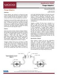
CLOSED LOOP POSITION CONTROL<br />
MODEL N121-132A<br />
SERVOCONTROLLER<br />
(<strong>Snap</strong>-<strong>Trac</strong> Card)<br />
A1A<br />
R8<br />
SCALE<br />
MODEL <strong>N123</strong>-<strong>138</strong><br />
DITHER GENERATOR<br />
(<strong>Snap</strong>-<strong>Trac</strong> Card)<br />
DITHER FREQ WAVEFORM<br />
A1A<br />
R8<br />
LOOP GAIN-1<br />
R9<br />
R11<br />
A1B A2B<br />
A1B<br />
Note: Consult <strong>Moog</strong> Servovalve Catalog for recommended<br />
dither Amplitude & Frequency. Select 'waveform' as per<br />
requirements of application <strong>and</strong> actual desired response.<br />
C3<br />
R46<br />
+E<br />
-E<br />
-E<br />
+E<br />
26<br />
27<br />
28<br />
29<br />
22<br />
18<br />
3<br />
12<br />
13<br />
19<br />
17<br />
21<br />
10<br />
2<br />
2<br />
6<br />
7<br />
9<br />
8<br />
115 VAC<br />
50-60 Hz<br />
Position Servo with <strong>Dither</strong> <strong>Generator</strong> Application<br />
-15V<br />
+15V<br />
+15V<br />
-15V<br />
Ps<br />
C2 C1<br />
ACTUATOR<br />
POSITION COMMAND<br />
SERVOVALVE<br />
R<br />
Questions & Answers<br />
Question: Can the <strong>Dither</strong> Frequency<br />
be set-up for either a ‘square wave’ or<br />
‘triangular wave’?<br />
Answer: The valve is usually run with<br />
the square wave output signal but will<br />
depend on the actual desired response.<br />
Square wave will provide a more<br />
abrupt control from hard over position<br />
whereas the Triangular wave will<br />
provide a softer control response. It<br />
will depend on valve ‘friction’ or<br />
‘sticking’ action caused by actuator or<br />
servovalve response. Research indicates<br />
that the type of waveform, whether<br />
sine, square or triangular shape, will not<br />
significantly effect the valve<br />
performance. It is strictly related to<br />
required frequency & amplitude for the<br />
specified valve hardware.<br />
Question: Does the type of<br />
servovalve used determine the<br />
frequency & amplitude?<br />
Answer: The card is factory set for<br />
400Hz frequency with an amplitude of<br />
16Vp-p.The <strong>Moog</strong> Servovalve Catalog<br />
should be consulted for recommended<br />
dither amplitude & frequency. If a<br />
competitors valve is used, consult the<br />
appropriate Factory as required.The<br />
actual frequency / amplitude will also<br />
be determined on the system set-up.<br />
Fine tuning may need to be applied to<br />
reach satisfactory results.As an<br />
example, a 760 <strong>Series</strong> valve may require<br />
a dither frequency of approximately<br />
400Hz at a current amplitude of 10mA<br />
peak-to-peak (series coil configuration).<br />
Caution is advised since the use of<br />
higher dither frequency other than<br />
specified, can excite internal valve<br />
resonance which may lead to valve<br />
failure or degrade the valve life. Proper<br />
FORCE<br />
ON<br />
LOAD<br />
POSITION FEEDBACK<br />
amplitude (% of valve current) should<br />
also be stressed so as not to exceed<br />
20% of rated current.<br />
Question: What purpose do the NF<br />
(non-furnished) components provide in<br />
the circuit such as pots R1, R14 <strong>and</strong><br />
R27? What are the recommended<br />
component sizes for setting up these<br />
feature adjustments?<br />
Answer: Installation of R1 provides<br />
adjustment of the ‘negative’ slope or<br />
ramp rate over a 12:1 ratio. R14<br />
provides adjustment of the ‘positive’<br />
slope or ramp rate over a 12:1 range.<br />
Recommended size is 100K for each.<br />
The voltage divider resistors must be<br />
removed for this feature to operate.<br />
(Remove R2, 3, 12 & 13)<br />
Question: What is the purpose of<br />
the Auxiliary general purpose amp?<br />
Answer: This stage is used for <strong>Dither</strong><br />
Amplitude Adj using R25 (Gain) pot of<br />
A2B Non-Inverting Stage. Connect<br />
Output Pin-2 (Sq Wave) or Pin-6<br />
(Triangle Wave) to Pin-13 (Single Input<br />
Signal) for amplitude adjustment using<br />
R25 for a 12:2 ratio amplification.A<br />
Zero Offset pot (R27) may be installed<br />
for ‘Bias’ signal control. Set R27 to<br />
100K Pot & R26 to 100K / 1% resistor.<br />
Question: How much <strong>Dither</strong> should<br />
be applied?<br />
Answer: If external dither is applied<br />
to Pin-1 or Pin-3, typically adjust for<br />
±10% of valve rated current. J1 & J2<br />
MUST be in the appropriate position.<br />
This follows true for Internal dither.<br />
Internal dither ±Slope is adjusted by<br />
pots R1 & R14 (customer installed).<br />
<strong>Dither</strong> current thru a servovalve<br />
should NOT exceed 20% of rated<br />
current.<br />
Industrial Controls Division<br />
<strong>Moog</strong> <strong>Inc</strong>., East Aurora, NY 14052-0018<br />
Telephone: 716/655-3000<br />
Fax: 716/655-1803<br />
Toll Free: 1-800-272-MOOG<br />
CDL6173 Rev B 500-199 1198