Slip Rings With Through-Bores
Slip Rings With Through-Bores
Slip Rings With Through-Bores

Create successful ePaper yourself
Turn your PDF publications into a flip-book with our unique Google optimized e-Paper software.
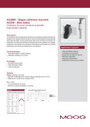
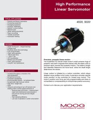
<strong>Slip</strong> <strong>Rings</strong> <strong>With</strong> <strong>Through</strong>-<strong>Bores</strong><br />
AC4598<br />
10 amp per circuit 1-1/2 inch through-bore<br />
Description<br />
A slip ring can be used in any electromechanical system that requires<br />
unrestrained, continuous rotation while transferring power and / or<br />
data from a stationary to a rotating structure. A slip ring is also called<br />
a rotary electrical interface, collector, swivel, or a rotary joint. A slip<br />
ring can improve system performance by simplifying operations<br />
and eliminating damage-prone wires dangling from movable joints.<br />
The 1-1/2 inch through-bore provides routing space for hydraulics,<br />
pneumatics or for a concentric shaft mount.<br />
The AC4598 uses our unique fiber brush technology which offers<br />
several advantages over conventional slip ring contacts, including<br />
multiple points of contact per brush bundle, low noise, electrical and<br />
low contact wear rates. In addition, fiber brushes do not require<br />
lubrication and produce virtually no wear debris.<br />
Features<br />
• 1-1/2 inch through-bore<br />
• Speeds up to 250 rpm continuous<br />
• 6, 12, 18 or 24 ten amp circuits<br />
• 16 gauge, 12 inch lead wire - longer lead lengths are available<br />
• Higher rotational speeds with alternate bearings (optional)<br />
• Various axial and radial lead exits are available<br />
• Splash seals for dust and moisture resistance<br />
• Standard collar mounting - flange mounting optional<br />
• Also available with 12, 24, 36 and 48, 2 amp rings or power and<br />
signal combinations. Please refer to AC6200 data sheet.<br />
• Available with Ethernet<br />
Benefits<br />
• Transfers analog and digital signals<br />
• Compatible with data bus protocols<br />
• Fiber brush technology provides long life and maintenance-free<br />
operation (no lubrication required)<br />
• Continuous 360° rotation of power or data signals<br />
Typical Applications<br />
• Industrial machinery - machining<br />
centers, rotary index tables, heavy<br />
equipment turrets or cable reels,<br />
test equipment, packaging<br />
machines, palletizing machines,<br />
magnetic clutches, process control<br />
equipment, rotary sensors,<br />
emergency lighting, robotics<br />
• Exhibit / display equipment<br />
• Medical equipment<br />
REVISED 11/12<br />
22 Moog Components Group • www.moog.com/components
*Please note that the operational life of the unit is dependent upon rotational speed, environment and temperature.<br />
<strong>Slip</strong> <strong>Rings</strong> <strong>With</strong> <strong>Through</strong>-<strong>Bores</strong><br />
AC4598 Specifications Options<br />
Operating Speed 250 rpm* continuous • 5 inch (127 mm) O.D. flange with 4 mounting<br />
Number of Circuits<br />
Lead Wire<br />
6, 12, 18 or 24<br />
16 gauge, 12 inches (300 mm)<br />
holes<br />
• Splash seals for dust and moisture resistance<br />
• Various axial and radial lead exits are available<br />
Voltage 600 VAC<br />
• Longer lead lengths are available<br />
Operating Temp.<br />
Current Rating<br />
-40°C to 80°C<br />
10 amp circuits<br />
• Higher rotational speeds with alternate bearings<br />
• Higher current and voltage capacity per circuit<br />
• Signal and power circuit combination<br />
Torque Approx. .5 in-oz (36.00 cm-g) per circuit unsealed<br />
• IP 65 rated slip ring available (P/N AC6419),<br />
Add approx. 10 in-oz (720.08 cm-g) for dust seals<br />
see page 26<br />
Noise Less than 100 milliohms peak @ 6 VDC, 50 mA, 5 rpm<br />
• Available with Ethernet, contact factory<br />
Sealed Units Optional intermittent splash and gross particle exclusion only<br />
Lead Wire Color Code<br />
Ring # Color Ring # Color Ring # Color Ring # Color Ring # Color Ring # Color<br />
1 Blk 5 Yel 9 Gry 13 Wht-Red 17 Wht-Blu 21 Wht-Blk-Red<br />
2 Brn 6 Grn 10 Wht 14 Wht-Orn 18 Wht-Vio 22 Wht-Blk-Orn<br />
3 Red 7 Blu 11 Wht-Blk 15 Wht-Yel 19 Wht-Gry 23 Wht-Blk-Yel<br />
4. Orn 8 Vio 12 Wht-Brn 16 Wht-Grn 20 Wht-Blk-Brn 24 Wht-Blk-Grn<br />
Notes:<br />
1. Drawings not actual size, measurements are in inches (millimeters)<br />
2. Rotor and stator leads exit 4 places, 90° apart, 6 leads per exit relative to circuit count<br />
3. = Flange mounted, add .21 (5,3) for flange, no collar ring<br />
Dimensions in inches (millimeters)<br />
REVISED 11/12<br />
Moog Components Group • www.moog.com/components 23 23