A Novel Blasted and Grooved Low Profile Pedicle Screw Able to ...
A Novel Blasted and Grooved Low Profile Pedicle Screw Able to ...
A Novel Blasted and Grooved Low Profile Pedicle Screw Able to ...

You also want an ePaper? Increase the reach of your titles
YUMPU automatically turns print PDFs into web optimized ePapers that Google loves.
SU Kuh, et al.<br />
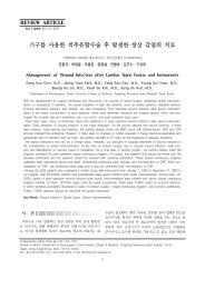
Fig. 1. The seven different types of pedicle screw evaluated: (A) universal polyaxial screw; (B) low profile polyaxial screw; (C) low profile<br />
polyaxial screw treated with blasting only; (D) low profile screw treated with grooving at 0.05 mm intervals; (E) low profile screw<br />
treated with blasting <strong>and</strong> grooving at 0.05 mm intervals; (F) low profile screw treated with blasting <strong>and</strong> grooving at 0.10 mm intervals<br />
<strong>and</strong> (G) low profile screw treated with blasting <strong>and</strong> grooving at 0.15 mm intervals.<br />
due the ball-<strong>and</strong>-socket-like structural characteristics of polyaxial<br />
pedicle screws.<br />
Our goal in this study was <strong>to</strong> develop a low profile polyaxial<br />
pedicle screw with a small screw head by decreasing the size<br />
of the fixture ball. Furthermore, <strong>to</strong> increase the coefficient of<br />
friction, we created grooves in the fixture ball <strong>and</strong>/or blasted<br />
it <strong>to</strong> improve the mechanical stability of the resulting low<br />
profile polyaxial pedicle screw. We evaluated the compression<br />
bending loads calculated by displacement <strong>and</strong> yield loads for<br />
a variety of screw head types that differed according <strong>to</strong> profile<br />
status, extent of grooves, <strong>and</strong> whether or not the fixture ball<br />
had been blasted.<br />
MATERIAL AND METHODS<br />
We evaluated seven different types of pedicle screws: univer-<br />
sal polyaxial screws, low profile polyaxial screws, low profile<br />
polyaxial screws treated with blasting only (blasting-only screw),<br />
low profile screws treated with grooving at 0.05 mm intervals<br />
(0.05 groove-only screws), low profile screws treated with blas-<br />
ting <strong>and</strong> grooving at 0.05 mm intervals (0.05 groove blasting<br />
screws), low profile screws treated with blasting <strong>and</strong> grooving<br />
at 0.10 mm intervals (0.10 groove blasting screws), <strong>and</strong> low<br />
profile screws treated with blasting <strong>and</strong> grooving at 0.15 mm<br />
intervals (0.15 groove blasting screws) (Fig. 1). <strong>Screw</strong>s were<br />
grooved by machining the fixture ball at regular intervals (Fig.<br />
2) <strong>and</strong> blasting treatment was performed by blasting the fixture<br />
ball of the screw with aluminum oxide(Al2O3)(Fig. 3).<br />
These screws are not commercially available; therefore, we<br />
made pro<strong>to</strong>types for the static compression test. All screws<br />
were made of titanium alloy (Ti-6AI-4V ELI). Furthermore,<br />
the length of the screw shaft was st<strong>and</strong>ardized <strong>to</strong> 40 mm <strong>and</strong><br />
the diameter <strong>to</strong> 6 mm. The screw shaft was potted in an ultra-<br />
high molecular weight polyethylene (UHMWPE) block <strong>and</strong> the<br />
screw head was mounted perpendicularly on a st<strong>and</strong>ardized<br />
rod (Ti-6AI-4V ELI alloy, diameter: 5.0 mm, length: 100.0 mm)<br />
at 1,000 N·cm 1) (Fig. 4). Construct rigidity was measured using<br />
62 www.e-kjs.org<br />
Fig. 2. Schematic illustration of the grooving method. The depth<br />
of the groove (A) was kept constant (0.1 mm) while the groove<br />
interval (B) was varied. The width of the groove (C) was made equal<br />
<strong>to</strong> the groove interval (B).<br />
Fig. 3. Electron microscopic views of a fixture ball pre- <strong>and</strong> postblasting.<br />
The surface of the blasted fixture ball (B) was rougher than<br />
that of the non-blasted fixture ball (A).<br />
a single column-type universal testing machine (RB 302 ML TM ;<br />
R&B Inc., Daejon, Korea) <strong>and</strong> ASTM F1717-09 (st<strong>and</strong>ard test<br />
methods for spinal implant constructs in a vertebrec<strong>to</strong>my model;<br />
ASTM international, West Conshohocken, PA, USA) was used<br />
as the test pro<strong>to</strong>col. Static compression bending force was<br />
applied at a point 40 mm from the screw insertion point perpen-<br />
dicular <strong>to</strong> the long axis of the screw. The compression force<br />
was applied at a rate of 25 mm/min. Outcomes including compressive<br />
bending ultimate load <strong>and</strong> compressive bending yield<br />
load were recorded at set intervals. The compressive bending<br />
yield load was defined as the force that caused a displacement<br />
at 2% offset yield <strong>and</strong> permanent deformation 1) . Each type<br />
of screw was tested five times. Comparison of yield loads based<br />
on screw type was performed using a one-way ANOVA. The<br />
level of significance was set at p