layout, design and construction handbook - California Department of ...
layout, design and construction handbook - California Department of ...
layout, design and construction handbook - California Department of ...

Create successful ePaper yourself
Turn your PDF publications into a flip-book with our unique Google optimized e-Paper software.
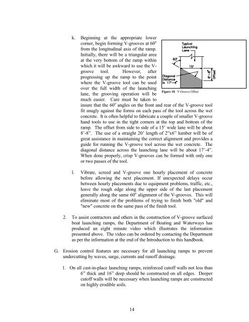
k. Beginning at the appropriate lower<br />
corner, begin forming V-grooves at 60 o<br />
from the longitudinal axis <strong>of</strong> the ramp.<br />
Initially, there will be a triangular area<br />
at the very bottom <strong>of</strong> the ramp within<br />
which it will be awkward to use the Vgroove<br />
tool. However, after<br />
progressing up the ramp to the point<br />
where the V-groove tool can be used<br />
over the full width <strong>of</strong> the launching<br />
lane, the grooving operation will be<br />
much easier. Care must be taken to<br />
insure that the 60 o Figure 18. V-Groove Offset<br />
angles on the front <strong>and</strong> rear <strong>of</strong> the V-groove tool<br />
fit snugly against the forms on each pass <strong>of</strong> the tool across the wet<br />
concrete. It is <strong>of</strong>ten helpful to fabricate a couple <strong>of</strong> smaller V-groove<br />
h<strong>and</strong> tools to use in the tight corners at the top <strong>and</strong> bottom <strong>of</strong> the<br />
ramp. The <strong>of</strong>fset from side to side <strong>of</strong> a 15’ wide lane will be about<br />
8’-8”. The use <strong>of</strong> a straight 20’ length <strong>of</strong> 2”x6” lumber will be <strong>of</strong><br />
great assistance in maintaining the correct alignment <strong>and</strong> provides a<br />
guide for running the V-groove tool across the wet concrete. The<br />
diagonal distance across the launching lane will be about 17’-4”.<br />
When done properly, crisp V-grooves can be formed with only one<br />
or two passes <strong>of</strong> the tool.<br />
l. Vibrate, screed <strong>and</strong> V-groove one hourly placement <strong>of</strong> concrete<br />
before allowing the next placement. If unexpected delays occur<br />
between hourly placements due to equipment problems, traffic, etc.,<br />
leave the rough edge along the upper side <strong>of</strong> the last placement<br />
generally along the same 60 o alignment <strong>of</strong> the V-grooves. This will<br />
eliminate most <strong>of</strong> the problems <strong>of</strong> trying to finish both "old" <strong>and</strong><br />
"new" concrete on the same pass <strong>of</strong> the finish tool.<br />
2. To assist contractors <strong>and</strong> others in the <strong>construction</strong> <strong>of</strong> V-groove surfaced<br />
boat launching ramps, the <strong>Department</strong> <strong>of</strong> Boating <strong>and</strong> Waterways has<br />
produced an eight minute video which illustrates the information<br />
presented above. The video can be ordered by contacting the <strong>Department</strong><br />
as per the information at the end <strong>of</strong> the Introduction to this h<strong>and</strong>book.<br />
G. Erosion control features are necessary for all launching ramps to prevent<br />
undercutting by waves, surge, currents <strong>and</strong> run<strong>of</strong>f drainage.<br />
1. On all cast-in-place launching ramps, reinforced cut<strong>of</strong>f walls not less than<br />
6” thick <strong>and</strong> 16” deep should be constructed on all edges. Deeper<br />
cut<strong>of</strong>f walls will be necessary when launching ramps are constructed<br />
on highly erodible soils.<br />
14