Fundamentals of Short-Circuit Protection for Transformers
Fundamentals of Short-Circuit Protection for Transformers
Fundamentals of Short-Circuit Protection for Transformers

Create successful ePaper yourself
Turn your PDF publications into a flip-book with our unique Google optimized e-Paper software.
The ATs on each <strong>of</strong> the core legs equal:<br />
AT = n • i<br />
n<br />
+<br />
2<br />
• i – i<br />
AT = n •i<br />
n<br />
+<br />
2<br />
• i – i<br />
AT = n • i<br />
n<br />
+<br />
2<br />
• i – i<br />
( )<br />
X<br />
1 H HA XA XB<br />
( )<br />
X<br />
2 H HB XB XC<br />
( )<br />
X<br />
3 H HC XC XA<br />
(25)<br />
Comparing the ATs on core leg pair 1 and 3 per (5) yields:<br />
nX<br />
AT 1 –AT3 = nH •( i HA –iHC) + •( 2•i XA –i XB –iXC)<br />
(26)<br />
2<br />
VH<br />
VX<br />
Considering that n ~ and n ~ 2• , we obtain:<br />
3 3<br />
H<br />
1 V 1<br />
AT – AT = i – i + • • 2 •i – i – i (27)<br />
X<br />
X<br />
( ) ( )<br />
1 3 HA HC XA XB XC<br />
3<br />
VH3 which yields the following differential signal:<br />
1 VX<br />
1<br />
iDIF() 1 = ( i HA –iHC ) + • •( 2•i XA –i XB –iXC<br />
) (28)<br />
3<br />
V 3<br />
H<br />
For the other two relay elements, we use (28) and rotate the<br />
subscript indices:<br />
1 VX<br />
1<br />
iDIF( 2)<br />
= ( i HB –iHA) + • •( 2•i XB –i XC –iXA<br />
) (29)<br />
3<br />
V 3<br />
H<br />
1 VX<br />
1<br />
iDIF( 3)<br />
= ( i HC –iHB ) + • •( 2•i XC –i XA –iXB<br />
) (30)<br />
3<br />
V 3<br />
H<br />
The appropriate compensation matrices in a<br />
microprocessor-based relay are:<br />
⎡ 1 0 –1⎤ ⎡ 2 –1 –1⎤<br />
1 1<br />
TH = •<br />
⎢<br />
–1 1 0<br />
⎥<br />
, TX •<br />
⎢<br />
–1 2 –1<br />
⎥<br />
3<br />
⎢ ⎥<br />
=<br />
3 ⎢ ⎥<br />
⎢⎣ 0 –1 1 ⎥⎦ ⎢⎣–1 –1 2 ⎥⎦<br />
(31)<br />
C. Summary <strong>of</strong> Compensation Matrices <strong>for</strong> Wye, Delta, and<br />
Zig-Zag Windings<br />
The TX matrix in (31) is <strong>of</strong>ten referred to as a double-delta<br />
connection, because it is equivalent to connecting the main<br />
CTs in delta and their secondary circuits in delta again when<br />
applying external compensation <strong>for</strong> electromechanical relays.<br />
The TH matrix in (31) is referred to as a single-delta<br />
connection. The TY matrix in (23) is referred to as a wye<br />
connection. In general, trans<strong>for</strong>mer delta windings require a<br />
wye compensation matrix, wye windings require a single-delta<br />
compensation matrix, and zig-zag windings require a doubledelta<br />
compensation matrix.<br />
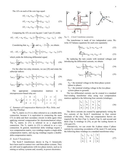
D. Scott-T Trans<strong>for</strong>mers<br />
The Scott-T trans<strong>for</strong>mers shown in Fig. 11 historically<br />
have been used to connect two- and three-phase systems. They<br />
are still used in applications with two-phase motors, such as in<br />
mining or railway systems and, recently, in power electronics.<br />
iHA iHB iHC<br />
0.5nH<br />
* *<br />
* *<br />
*<br />
iXD<br />
3<br />
nH<br />
2<br />
nX<br />
nX<br />
0.5nH<br />
iXQ<br />
Fig. 11. A Scott-T trans<strong>for</strong>mer connection.<br />
The trans<strong>for</strong>mer is made <strong>of</strong> two independent cores. We<br />
write AT balance equations <strong>for</strong> each core separately:<br />
nH<br />
( i HA –iHC ) + nX•iXD = 0<br />
(32)<br />
2<br />
VQ<br />
VC<br />
3•nH •iHB nX •iXQ 0<br />
+ = (33)<br />
2<br />
By replacing the turn counts with nominal voltages and<br />
introducing the differential currents, we obtain:<br />
where:<br />
X<br />
VB<br />
90°<br />
VH<br />
iDIF() 1 = •( i HA –iHC ) + iXD<br />
(34)<br />
2•V<br />
3•VH<br />
iDIF( 2)<br />
= •iHB + iXQ<br />
(35)<br />
2•V<br />
VH = the nominal voltage in the three-phase system<br />
(phase to phase).<br />
VX = the nominal winding voltage in the two-phase<br />
system (phase to ground).<br />
The two differential currents can be created in a standard<br />
four-winding trans<strong>for</strong>mer relay using wye compensation<br />
matrices applied to the following four currents (windings):<br />
⎡iD⎤ ⎡i A⎤ ⎡–iC⎤ ⎡0⎤ ⎢<br />
i<br />
⎥<br />
Q ,<br />
⎢<br />
0<br />
⎥<br />
,<br />
⎢<br />
0<br />
⎥<br />
,<br />
⎢<br />
i<br />
⎥<br />
⎢ ⎥ ⎢ ⎥ ⎢ ⎥ ⎢ B⎥<br />
(36)<br />
⎢⎣ 0⎥⎦ ⎢⎣0⎥⎦ ⎢⎣ 0 ⎥⎦ ⎢⎣0⎥⎦ The above currents are created by appropriately wiring the<br />
five currents <strong>of</strong> the Scott-T trans<strong>for</strong>mer to four current<br />
terminals <strong>of</strong> the relay. Three tap compensation factors are<br />
required <strong>for</strong> the first (Tap 1), fourth (Tap 2), and second and<br />
third (Tap 3) windings in (36), as per the scaling factors in<br />
(34) and (35).<br />
Alternatively, we can create the A-phase minus C-phase<br />
currents by connecting secondaries <strong>of</strong> the main CTs and using<br />
the following three windings in a standard trans<strong>for</strong>mer relay:<br />
⎡iD⎤ ⎡i A –iC⎤ ⎡0⎤ ⎢<br />
i<br />
⎥<br />
Q ,<br />
⎢<br />
0<br />
⎥<br />
,<br />
⎢<br />
i<br />
⎥<br />
⎢ ⎥ ⎢ ⎥ ⎢ B⎥<br />
(37)<br />
⎢⎣ 0⎥⎦ ⎢⎣ 0 ⎥⎦ ⎢⎣0⎥⎦ X<br />
VA<br />
VD<br />
8