Fundamentals of Short-Circuit Protection for Transformers
Fundamentals of Short-Circuit Protection for Transformers
Fundamentals of Short-Circuit Protection for Transformers

Create successful ePaper yourself
Turn your PDF publications into a flip-book with our unique Google optimized e-Paper software.
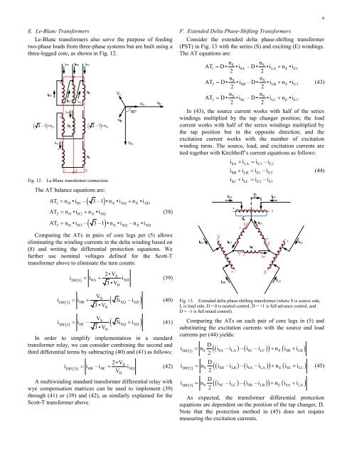
E. Le-Blanc Trans<strong>for</strong>mers<br />
Le-Blanc trans<strong>for</strong>mers also serve the purpose <strong>of</strong> feeding<br />
two-phase loads from three-phase systems but are built using a<br />
three-legged core, as shown in Fig. 12.<br />
( 3 −1) •nX<br />
* *<br />
*<br />
( 3 −1) •nX<br />
Fig. 12. Le-Blanc trans<strong>for</strong>mer connection.<br />
The AT balance equations are:<br />
( )<br />
AT = n •i – 3 –1 •n •i + n •i<br />
1 H H1 X XQ X XD<br />
AT = n •i + n • i<br />
2 H H2 X XQ<br />
( )<br />
AT = n •i – 3 –1 •n •i –n •i<br />
3 H H3 X XQ X XD<br />
(38)<br />
Comparing the ATs in pairs <strong>of</strong> core legs per (5) allows<br />
eliminating the winding currents in the delta winding based on<br />
(8) and writing the differential protection equations. We<br />
further use nominal voltages defined <strong>for</strong> the Scott-T<br />
trans<strong>for</strong>mer above to eliminate the turn counts:<br />
2•VX<br />
iDIF() 1 = iHA + iXD<br />
(39)<br />
3•V<br />
VX<br />
( ) HB ( XQ XD )<br />
iDIF 2 = i + 3i –i<br />
(40)<br />
3•V<br />
VX<br />
( ) HC ( XQ XD )<br />
H<br />
iDIF 3 = i – 3i + i<br />
(41)<br />
3•V<br />
In order to simplify implementation in a standard<br />
trans<strong>for</strong>mer relay, we can consider combining the second and<br />
third differential terms by subtracting (40) and (41) as follows:<br />
H<br />
H<br />
2•VX<br />
iDIF( 23)<br />
= i HB –iHC + iXQ<br />
(42)<br />
V<br />
A multiwinding standard trans<strong>for</strong>mer differential relay with<br />
wye compensation matrices can be used to implement (39)<br />
through (41) or (39) and (42), as similarly explained <strong>for</strong> the<br />
Scott-T trans<strong>for</strong>mer above.<br />
H<br />
F. Extended Delta Phase-Shifting Trans<strong>for</strong>mers<br />
Consider the extended delta phase-shifting trans<strong>for</strong>mer<br />
(PST) in Fig. 13 with the series (S) and exciting (E) windings.<br />
The AT equations are:<br />
nS nS<br />
AT1 = D• •i SA –D• •iLA + nE •iE1<br />
2 2<br />
nS nS<br />
AT2 = D• •i SB –D• •iLB + nE •iE2<br />
(43)<br />
2 2<br />
nS nS<br />
AT3 = D• •i SC –D• •iLC + nE •iE3<br />
2 2<br />
In (43), the source current works with half <strong>of</strong> the series<br />
windings multiplied by the tap changer position; the load<br />
current works with half <strong>of</strong> the series windings multiplied by<br />
the tap position but in the opposite direction; and the<br />
excitation current works with the number <strong>of</strong> excitation<br />
winding turns. The source, load, and excitation currents are<br />
tied together with Kirchh<strong>of</strong>f’s current equations as follows:<br />
iSA + iLA= i E3 –iE2<br />
iSB+ iLB = i E1 –iE3<br />
(44)<br />
i + i = i –i<br />
*<br />
SC LC E2 E1<br />
Fig. 13. Extended delta phase-shifting trans<strong>for</strong>mer (where S is source side,<br />
L is load side, D = 0 is neutral control, D = +1 is full advance control, and<br />
D = –1 is full retard control).<br />
Comparing the ATs on each pair <strong>of</strong> core legs in (5) and<br />
substituting the excitation currents with the source and load<br />
currents per (44) yields:<br />
i () = DIF 1 n<br />
D<br />
2<br />
( i –i ) – ( i –i ) + n i + i<br />
iDIF( 2)<br />
= n<br />
D<br />
2<br />
( i –i ) – ( i –i ) + n i + i<br />
iDIF( 3)<br />
= n<br />
D<br />
2<br />
( i –i ) – ( i –i ) + n i + i<br />
*<br />
( ) ( )<br />
S SA LA SC LC E SB LB<br />
( ) ( )<br />
S SB LB SA LA E SC LC<br />
( ) ( )<br />
S SC LC SB LB E SA LA<br />
9<br />
(45)<br />
As expected, the trans<strong>for</strong>mer differential protection<br />
equations are dependent on the position <strong>of</strong> the tap changer, D.<br />
Note that the protection method in (45) does not require<br />
measuring the excitation currents.