SHORT SPAN BRIDGES CONDUIT FORMATIONS A A ELEVATION ...
SHORT SPAN BRIDGES CONDUIT FORMATIONS A A ELEVATION ...
SHORT SPAN BRIDGES CONDUIT FORMATIONS A A ELEVATION ...

Create successful ePaper yourself
Turn your PDF publications into a flip-book with our unique Google optimized e-Paper software.
tc6.dgn<br />
08-07-2012<br />
BTC-6<br />
Approach slab or<br />
drainage apron<br />
12"<br />
3<br />
Limit of conduit<br />
in bridge contract<br />
Wrap with a non-rigid<br />
material (" thickness)<br />
before filling backwall<br />
recess with grout or<br />
placing backwall<br />
concrete<br />
ABUTMENT<br />
1 4" o / PVC-D duct<br />
5<br />
4" / o galv. steel duct<br />
4" o / PVC-B duct<br />
PVC-galv. adaptor<br />
6’ max.<br />
4 5 1<br />
Varies<br />
Sealed and Signed by:<br />
Julius F.J. Volgyi Jr.<br />
Lic. No. 010487<br />
On the date of<br />
Aug. 7, 2012<br />
A copy of the original<br />
sealed and signed<br />
standard drawing<br />
is on file in the<br />
Central Office.<br />
VDOT S&B DIVISION<br />
RICHMOND, VA<br />
STRUCTURAL ENGINEER<br />
1"<br />
2<br />
3"<br />
2<br />
3<br />
4<br />
Existing structure<br />
50’ max.<br />
8’ max.<br />
Detail A<br />
PL 8 x<br />
Bond " mounting<br />
PL to beam with<br />
epoxy mortar<br />
6<br />
7<br />
Flat washer typ.<br />
"<br />
4 "<br />
4 "<br />
"<br />
L 5 x 3 x<br />
2"<br />
6<br />
7<br />
" o / galv. rod or<br />
galv. bolt w/lock<br />
nut ea. end typ.<br />
Galv.-PVC adaptor<br />
PVC exp. joint<br />
PVC lock ring<br />
PIER<br />
50’ max.<br />
100’ max. typ.<br />
Level<br />
1" 5" 5" 5" 5" 1"<br />
TYPICAL SUPPORT DETAIL<br />
1 6<br />
8’ max.<br />
typ.<br />
8’ max.<br />
Expansion joint bay<br />
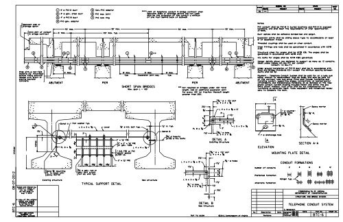
<strong>SHORT</strong> <strong>SPAN</strong> <strong>BRIDGES</strong><br />
Max. span L = 100’<br />
" o / H.S. bolt typ.<br />
2" x " FRE<br />
2" x 2" x " FRE<br />
or galv. tube<br />
1" O.D. FRE or PVC<br />
tubular spacer<br />
0.755" I.D.<br />
2" x " FRE<br />
L 4 x 4 x<br />
Limit of telephone conduit in bridge contract when<br />
approach slabs or drainage aprons are not used<br />
shall be the extension of the conduit a minimum<br />
of one foot behind back of backwall<br />
New structure<br />
8’ max.<br />
typ.<br />
" cl. typ.<br />
Detail B<br />
50’ max.<br />
" o / inserts<br />
w/" o / H.S. bolts<br />
PIER ABUTMENT<br />
Not required on bridges under 100’ total<br />
length. Add an additional expansion joint<br />
for every 100’ (or fraction thereof) length<br />
greater than 200’.<br />
" o hole /<br />
L 5 x 3 x<br />
2"<br />
L 4 x 4 x x 9"<br />
1"<br />
L 5 x 3 x<br />
PL 8 x<br />
2"<br />
"<br />
4"<br />
4"<br />
Not to scale<br />
1"<br />
DETAIL B<br />
7 6<br />
3"<br />
3"<br />
DETAIL A<br />
" o / x 1" slot<br />
L 4 x 4 x<br />
1"<br />
New Structure<br />
3"<br />
3"<br />
50’ max.<br />
" o / x 1" slot<br />
" o hole /<br />
L 5 x 3 x<br />
1"<br />
1"<br />
L 4 x 4 x<br />
2"<br />
1 5<br />
L 4 x 4 x x 6"<br />
Existing Structure<br />
1"<br />
" o holes<br />
/<br />
L 5 x 3 x<br />
c 2012, Commonwealth of Virginia<br />
2<br />
STATE<br />
ROUTE<br />
VA.<br />
Notes:<br />
8"<br />
1" / o anchorage hole<br />
A<br />
<strong>ELEVATION</strong><br />
A<br />
Number of conduits<br />
Preferred formation<br />
Alternate formation<br />
No. Description Date<br />
Revisions<br />
FEDERAL AID<br />
PROJECT ROUTE PROJECT<br />
1" / o counter-<br />
sunk holes<br />
in " PL<br />
" PL<br />
<strong>CONDUIT</strong> <strong>FORMATIONS</strong><br />
Hanger typ.<br />
1<br />
1<br />
SECTION A-A<br />
MOUNTING PLATE DETAIL<br />
" PL<br />
Epoxy mortar<br />
Epoxy mortar<br />
2 4 6 8 12<br />
TELEPHONE <strong>CONDUIT</strong> SYSTEM<br />
G. Henderson<br />
STATE<br />
PVC conduit shall be PVC-B in buried locations and PVC-D in exposed<br />
locations, and shall meet the requirements of AT&T Specification<br />
AT-8546.<br />
Duct splices shall be adhesive bonded bell and spigot.<br />
Expansion joints shall be sliding sleeve type to accommodate at least<br />
6" of expansion travel.<br />
Threaded couplings shall be used on steel conduit.<br />
Steel fittings and rods shall be galvanized in accordance with ASTM<br />
A153.<br />
Structural steel for angles shall be ASTM A36. The angles shall be<br />
galvanized in accordance with ASTM A123.<br />
H.S. bolts for angles shall be ASTM A325 galvanized.<br />
Under ground installation of PVC-B duct shall be in accordance with<br />
Road and Bridge Standards ECI-I except the minimum spacing between<br />
ducts shall be ".<br />
COMMONWEALTH OF VIRGINIA<br />
DEPARTMENT OF TRANSPORTATION<br />
STRUCTURE AND BRIDGE DIVISION<br />
SHEET<br />
Hanger details shown are designed to support as many as 12 conduits.<br />
Dead Loads: Cables: 8.5 lbs./ft. per conduit<br />
Conduit: 1.5 lbs./ft.<br />
Payment - Telephone Conduit System shall be paid for on a lump sum<br />
basis, wherein no measurement shall be made, and shall be paid for<br />
at the contract lump sum price. Price shall include furnishing and<br />
installing conduit, supporting angles, connections, all related parts/<br />
attachments and miscellaneous hardware; all as detailed on the Tele-<br />
phone Conduit System drawing included herein and within the pay<br />
limits shown thereon. Such price shall be full compensation for<br />
furnishing all materials, labor, tools, equipment and incidentals neces-<br />
sary to complete the work.<br />
NO.<br />
Designed: S&B ........... DIV Date Plan No. Sheet No.<br />
Drawn: ................ S&B DIV<br />
Checked: S&B ............ DIV BTC-6
NOTES TO DESIGNER:<br />
TELEPHONE <strong>CONDUIT</strong> SYSTEM<br />
PVC <strong>CONDUIT</strong><br />
PRESTRESSED CONCRETE BEAM <strong>SPAN</strong>S<br />
Standard is for use with: PVC conduit<br />
prestressed concrete Bulb-T beam spans<br />
Show dimension from bottom of beam to bottom of angle support at the beam/girder the<br />
dimension is set on the transverse section sheet. When setting the dimension, allow for a<br />
minimum of 1” (2” to 3” preferred) clearance to diaphragms, cross frames, etc. Include insulation<br />
requirements when setting clearances.<br />
Utilities shall be placed in the exterior bays of the bridge if possible.<br />
ADD THE FOLLOWING NOTES, DIMENSIONS, DETAILS, ETC. TO STANDARD:<br />
TYPICAL SUPPORT DETAIL:<br />
Enter dimension from bottom of beam to L 5 x 3 x 3 /8 support. This must agree with dimension<br />
set on transverse section sheet.<br />
STANDARD BTC-6: NOTES TO DESIGNER<br />
VOL. V - PART 3<br />
DATE: 29May2009<br />
SHEET 2 of 2<br />
FILE NO. BTC-6-2