

Volar Distal Radius Locking Plate - Wheeless' Textbook of ...
Volar Distal Radius Locking Plate - Wheeless' Textbook of ...
Volar Distal Radius Locking Plate - Wheeless' Textbook of ...

Create successful ePaper yourself
Turn your PDF publications into a flip-book with our unique Google optimized e-Paper software.
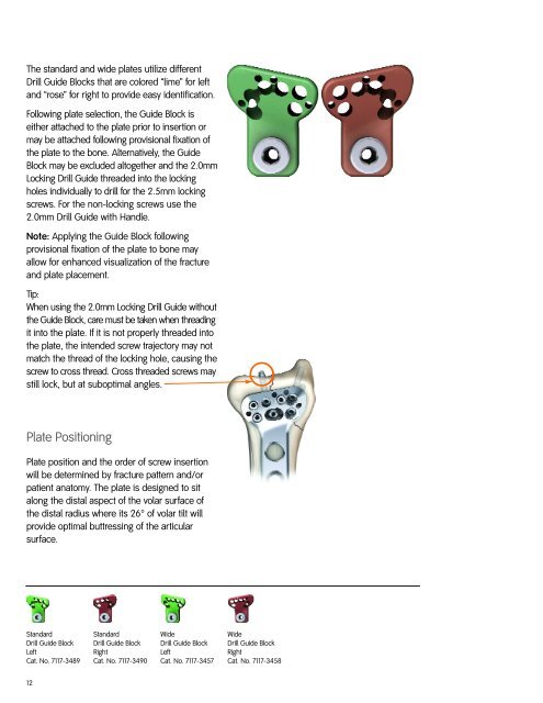
The standard and wide plates utilize different<br />
Drill Guide Blocks that are colored “lime” for left<br />
and “rose” for right to provide easy identification.<br />
Following plate selection, the Guide Block is<br />
either attached to the plate prior to insertion or<br />
may be attached following provisional fixation <strong>of</strong><br />
the plate to the bone. Alternatively, the Guide<br />
Block may be excluded altogether and the 2.0mm<br />
<strong>Locking</strong> Drill Guide threaded into the locking<br />
holes individually to drill for the 2.5mm locking<br />
screws. For the non-locking screws use the<br />
2.0mm Drill Guide with Handle.<br />
Note: Applying the Guide Block following<br />
provisional fixation <strong>of</strong> the plate to bone may<br />
allow for enhanced visualization <strong>of</strong> the fracture<br />
and plate placement.<br />
Tip:<br />
When using the 2.0mm <strong>Locking</strong> Drill Guide without<br />
the Guide Block, care must be taken when threading<br />
it into the plate. If it is not properly threaded into<br />
the plate, the intended screw trajectory may not<br />
match the thread <strong>of</strong> the locking hole, causing the<br />
screw to cross thread. Cross threaded screws may<br />
still lock, but at suboptimal angles.<br />
<strong>Plate</strong> Positioning<br />
<strong>Plate</strong> position and the order <strong>of</strong> screw insertion<br />
will be determined by fracture pattern and/or<br />
patient anatomy. The plate is designed to sit<br />
along the distal aspect <strong>of</strong> the volar surface <strong>of</strong><br />
the distal radius where its 26° <strong>of</strong> volar tilt will<br />
provide optimal buttressing <strong>of</strong> the articular<br />
surface.<br />
Standard<br />
Drill Guide Block<br />
Left<br />
Cat. No. 7117-3489<br />
12<br />
Standard<br />
Drill Guide Block<br />
Right<br />
Cat. No. 7117-3490<br />
Wide<br />
Drill Guide Block<br />
Left<br />
Cat. No. 7117-3457<br />
Wide<br />
Drill Guide Block<br />
Right<br />
Cat. No. 7117-3458