Brushless Constant-Voltage Synchronous - Uljanik TESU dd
Brushless Constant-Voltage Synchronous - Uljanik TESU dd
Brushless Constant-Voltage Synchronous - Uljanik TESU dd

Create successful ePaper yourself
Turn your PDF publications into a flip-book with our unique Google optimized e-Paper software.
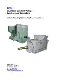
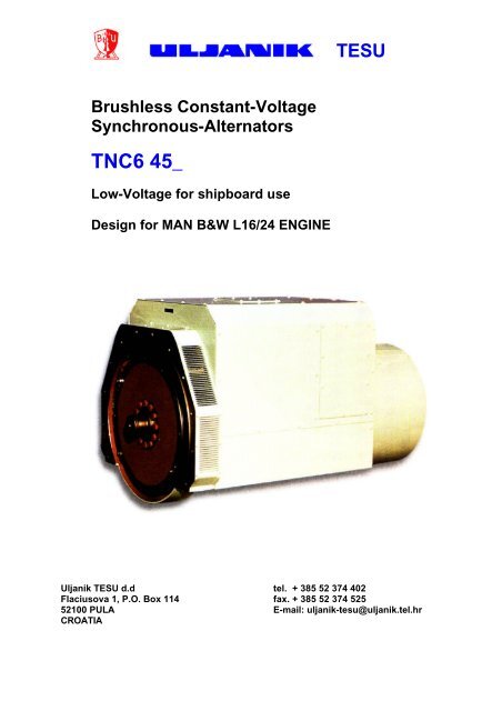
<strong>Brushless</strong> <strong>Constant</strong>-<strong>Voltage</strong><br />
<strong>Synchronous</strong>-Alternators<br />
TNC6 45_<br />
Low-<strong>Voltage</strong> for shipboard use<br />
Design for MAN B&W L16/24 ENGINE<br />
<strong>TESU</strong><br />
<strong>Uljanik</strong> <strong>TESU</strong> d.d tel. + 385 52 374 402<br />
Flaciusova 1, P.O. Box 114 fax. + 385 52 374 525<br />
52100 PULA E-mail: uljanik-tesu@uljanik.tel.hr<br />
CROATIA
2<br />
<strong>Brushless</strong> <strong>Constant</strong>-<strong>Voltage</strong> <strong>Synchronous</strong>-Alternators TNC6 45_ 6<br />
Brusless alternators family TNC6 45_ 6 are the result of our many years<br />
of experience in design and production of alternators and technical<br />
requests of the diesel engines producer MAN B&W Holeby.<br />
Alternators are special designed to the MAN B&W specifications and<br />
they are intended for coupling to the engines family L16/24 for marine<br />
gensets.<br />
Engine types and appertaining alternators can be founded in the table<br />
below.<br />
MAN B&W Holeby<br />
diesel engine<br />
Altrnator type<br />
5L 16/24 TNC6 455 6<br />
6L 16/24 TNC6 456 6<br />
7L 16/24 TNC6 457 6<br />
8L 16/24 TNC6 458 6<br />
9L 16/24 TNC6 459 6<br />
This catalogue contains technical data with basic description of design<br />
and the alternator dimensions.
Contents<br />
1. General information ……………………………………………………… 4<br />
2. Electrical characteristic at 50Hz ……………………………………….. 5<br />
3. Electrical characteristic at 60Hz ……………………………………….. 6<br />
4. Technical data ……………………………………………………………. 7<br />
4.1. TNC6 45_ 6 general cut wiew ………………………………………. 7<br />
4.2. Stator …………………………………………………………………... 8<br />
4.2.1 Main stator ……………………………………………………. 8<br />
4.2.2. Exciter stator ………………………………………………….. 8<br />
4.2.3. PMG stator ……………………………………………………. 8<br />
4.2.4. Anti condensation heating ……………………………………. 9<br />
4.2.5. Alternator protection equipment ……………………………… 9<br />
4.2.6. Terminal box …………………………………………………… 9<br />
4.2.7. Cover …………………………………………………………… 10<br />
4.2.8. Lifting eyes ……………………………………………………... 10<br />
4.2.9. Genset elastic mounting element acces ……………………..10<br />
4.2.10. Coupling screws access ………………………………………. 10<br />
4.2.11. Voltege regulator access ………………………………………10<br />
4.2.12. Nameplate ……………………………………………………….11<br />
4.3. Rotor ……………………………………………………………………… 12<br />
4.3.1. Main rotor ………………………………………………………. 12<br />
4.3.2. Exciter rotor ……………………………………………………. 13<br />
4.3.3. PMG rotor ……………………………………………………… 13<br />
4.3.4. Rotating rectifier ……………………………………………….. 13<br />
4.3.5. Fan ………………………………………………………………. 13<br />
4.4. Coupling ………………………………………………………………….. 13<br />
4.5. Ball Bearing ………………………………………………………………14<br />
4.6. Excitation system ……………………………………………………….. 15<br />
4.6.1. Mode of operation ……………………………………………….15<br />
4.6.2. <strong>Voltage</strong> Regulator ………………………………………………. 15<br />
4.6.3. Overvoltage suicide circuit ……………………………………..16<br />
4.6.4. Parallel operation ………………………………………………..17<br />
5. Spare parts …………………………………………………………………….. 18<br />
6. Dimension drawing ……………………………………………………………. 19<br />
7. Dimension drawing of shaft ………………………………………………….. 20<br />
8. Electrical diagram ………………………………………………………………21<br />
3
Alternator<br />
4<br />
1. General iformation<br />
The alternator is a brushless constant voltage synchronous machine. The machine is of<br />
the self-excited type with an automatic voltage regulator.<br />
Exciter<br />
The machine has a shaft-mounted exciter on the side of the non-drive end shield. The<br />
main machine field winding is powered from the exciter rotor winding via a rotating, threephase<br />
bridge-connected rectifier set.<br />
Excitation system<br />
The exciting current for the exciter is supplied by the PMG via the electronic voltage<br />
regulator. The regulator and the PMG are placed on the side of the non-drive end shield,<br />
under the end-mounted cover.<br />
Vibration stability<br />
The alternator fulfils the requirements concerning vibrations in accordance with the<br />
standard ISO 8528-9.<br />
Standards and Requirements<br />
The alternators conform to applicable IEC requirements, DIN standards and VDE codes<br />
and particularly to VDE 0530, Specification for rotating electrical machines.<br />
The alternators also conform to the requirements of the following classification societies:<br />
Classification society Abbreviation Coolant temperature (CT) 0C<br />
American Bureau of Shipping ABS 50<br />
Bureau Veritas BV 40,45, 50<br />
Germanischer Lloyd GL 40, 45<br />
Lloyd's Register of Shipping LRS 40, 45, 50<br />
Det Norske Veritas NV 35, 45<br />
Registro Italiano Navale RINa 45, 50<br />
Marine alternators can also be supplied to satisfy the requirements of other classification<br />
societies such as
2. Electrical characteristics at 50 Hz<br />
Electrical frequency: f = 50 Hz Insulation class: H<br />
Speed: n = 1000 rpm Temperature rise: F *<br />
<strong>Voltage</strong>: U = 400 V Winding pitch: 6/7.5<br />
Ambient temperature: 45 °C Designed according to the marine<br />
Protection: IP23 classification rules<br />
Mounting of air filter inlet gives no reduction in kW output of the alternator.<br />
Engine type 6L 16/24 7L 16/24 8L 16/24 9L 16/24<br />
Alternator type TNC6 456-6 TNC6 457-7 TNC6 458-6 TNC6 459-6<br />
kW 540 630 720 810<br />
kVA 636 743 850 955<br />
Efficiency (%) at power factor=0.8 (IEC standard)<br />
Power : 100% 94.1 94.2 94.5 94.3<br />
Power : 75% 94.3 94.4 94.6 94.4<br />
Power : 50% 94.1 94.5 94.5 94.0<br />
Power : 25% 92.0 92.6 92.5 91.1<br />
Efficiency (%) at power factor=1 (IEC standard)<br />
Power : 100% 95.4 95.5 95.7 95.8<br />
Power : 75% 95.7 95.9 96.0 95.9<br />
Power : 50% 95.6 95.9 95.9 95.6<br />
Power : 25% 93.8 94.3 94.2 93.1<br />
Reactances (%)<br />
Xd 284 331 306 206<br />
Xq 216 252 234 158<br />
Xd' 16.9 18.5 17.1 14.4<br />
Xd'' 14.4 15.6 14.4 12.3<br />
Xq'' 15.4 16.4 15 13.1<br />
X2 14.3 16 14.6 12.7<br />
Xo 6.8 7.1 7 5.8<br />
Kcc 0.35 0.30 0.33 0.48<br />
Time constants (Second)<br />
T'do 1.51 1.6 1.85 1.3<br />
T'd 0.09 0.09 0.103 0.091<br />
T''d 0.004 0.004 0.004 0.004<br />
Ta 0.03 0.032 0.036 0.03<br />
Short circuit current (A)<br />
Maximum s.c. current Js<br />
(peak value)<br />
Steady s.c. current JKD<br />
(rms value)<br />
13450 14580 18490 23700<br />
2840 3320 3800 4270<br />
* Except for 9L 16/24 - 1000 rpm. Here the temperature rise of the alternator is class H or reduction<br />
in power output for temperature rise class F.<br />
5
6<br />
3. Electrical characteristics at 60 Hz<br />
Electrical frequency: f = 60 Hz Insulation class: H<br />
Speed: n = 1200 rpm Temperature rise: F<br />
<strong>Voltage</strong>: U = 450 V Winding pitch: 6/7.5<br />
Ambient temperature: 45 °C Designed according to the marine<br />
Protection: IP23 classification rules<br />
Mounting of air filter inlet gives no reduction in kW output of the alternator.<br />
Engine type 5L 16/24 6L 16/24 7L 16/24 8L 16/24 9L 16/24<br />
Alternator type TNC6 455-6 TNC6 456-6 TNC6 457-6 TNC6 458-6 TNC6 459-6<br />
kW 500 600 700 800 900<br />
kVA 591 708 827 950 1066<br />
Efficiency (%) at power factor=0.8 (IEC standard)<br />
Power : 100% 94.6 94.4 94.5 95.0 94.7<br />
Power : 75% 94.7 94.7 94.8 95.0 94.7<br />
Power : 50% 94.1 94.4 94.7 94.7 94.3<br />
Power : 25% 91.2 92.0 92.6 92.5 91.2<br />
Efficiency (%) at power factor=1 (IEC standard)<br />
Power : 100% 96.0 95.7 95.8 96.0 96.1<br />
Power : 75% 96.0 96.0 96.1 96.2 96.1<br />
Power : 50% 95.6 95.7 95.9 95.9 95.7<br />
Power : 25% 93.1 93.7 94.2 94.1 93.0<br />
Reactances (%)<br />
Xd 272 336 386 364 259<br />
Xq 208 256 294 277 198<br />
Xd' 15.7 18 19.5 18.2 15.1<br />
Xd'' 13.2 14.9 16.3 15 12.6<br />
Xq'' 14.3 16.2 17.2 15.9 13.5<br />
X2 13.7 15.5 16.7 15.4 13.1<br />
Xo 6.4 7.6 7.9 7.8 6.5<br />
Kcc 0.37 0.30 0.26 0.27 0.39<br />
Time constants (Second)<br />
T'do 1.54 1.68 1.8 2.06 1.58<br />
T'd 0.089 0.09 0.091 0.103 0.092<br />
T''d 0.004 0.004 0.004 0.004 0.004<br />
Ta 0.03 0.03 0.032 0.036 0.03<br />
Short circuit current (A)<br />
Maximum s.c.<br />
current Js<br />
(peak value)<br />
12580 13260 14350 18140 23730<br />
Steady s.c.<br />
current JKD<br />
(rms value)<br />
2657 3360 3920 4500 5060
4.1. TNC6 45_ General cut view<br />
4. Technical data<br />
This figure represents the general section where all main parts of alternator can be seen.<br />
1 Shaft 11 End shield<br />
2 Drive hub 12 <strong>Voltage</strong> regulator<br />
3 Flexplate 13 Ball bearing<br />
4 Fan 14 Air inlet cover (filter at option)<br />
5 Fan housing 15 Exciter field<br />
6 Rotor core and winding 16 Exciter armature<br />
7 Stator core and winding 17 Rotating rectifier<br />
8 Stator frame 18 Stator PMG<br />
9 Terminal box housing 19 Rotor PMG<br />
10 Terminals<br />
7
4.2. Stator<br />
4.2.1 Main stator<br />
Stator core<br />
8<br />
4. Technical data<br />
The stator core of the main machine is made of high-quality, both sides insulated electrical<br />
sheet steel. It is subdivided into packets by means of ventilating ducts and spacers thus<br />
ensuring effective cooling. The complete core with winding is pressed into the housing.<br />
Stator winding<br />
Applying the most recent developments in engineering and materials is making stator<br />
winding.<br />
The alternator windings are manufactured in insulation system which satisfies class H.<br />
The insulation materials used are non-hydroscopic, non-tracking and withstand severe<br />
thermal stressing.<br />
The stator windings of the alternators are made of special enameled cooper wire.<br />
The standard insulation uses a special resin impregnation process.<br />
This results in high mechanical strength, vibration resistance and excellent dielectric<br />
strength.<br />
4.2.2 Exciter stator<br />
The stator of the exciter is mounted on the end shield at the non-drive end.<br />
The exciter field winding is made of enamelled cooper wire.<br />
It is H class insulated and resin impregnated.<br />
4.2.3 PMG stator<br />
The stator of the PMG is accommodated between an exciter and bearing mounted on the<br />
end shield.<br />
The stator core of the PMG machine is made of both sides insulated electrical sheet steel.<br />
The armature winding of the PMG is made of enamelled copper wire and class H<br />
insulated.
4.2.4. Anti-condensation heating<br />
4. Technical data<br />
Anti-condensation heating is installed in the alternator. It is recommended that heating<br />
element starts up when the alternator is stopped. It is connected to the auxiliary terminals.<br />
The anti-condensation heater requires a voltage of 220 V and has heat output of 250W.<br />
4.2.5. Alternator protection equipment<br />
The stator winding is provided with thermal protection in the form of resistance<br />
thermometers. The resistance thermometers are of the PT100 type and are connected to<br />
the auxiliary terminals.<br />
4.2.6. Terminal box<br />
The main terminal box of the alternator is located on the machine top.<br />
The neutral and phase wires are connected to the bars, one bar per phase and one bar<br />
per neutral line.<br />
The openings provide access to the terminals.<br />
The connection of accessories is carried out on auxiliary terminals.<br />
The terminal strips are located on the opposite side of main terminal<br />
Main terminals<br />
The alternator main terminals are marked U, V, W.<br />
The access to the main terminals is enabled by removing the panel pos.3 from the<br />
alternator cover. (fig. on page 10)<br />
The main cables entry is provided from the bottom, under the alternator cover.<br />
Inside alternator, the cables are fixed to the cable trays.<br />
For cables laying and cables trays access it is necessary to remove the panel (pos. 2) in<br />
a<strong>dd</strong>ition to panel (pos. 3). (fig. on page 10)<br />
Auxiliary terminals<br />
The auxiliary terminals are located under the alternator cover opposite the main terminals.<br />
For the auxiliary terminals access it is necessary to remove the panel (pos. 3) opposite to<br />
the main terminals panel. (fig. on page 10)<br />
9
4.2.7. Cover<br />
10<br />
4. Technical data<br />
Alternator cover is placed as shown in figure below<br />
4.2.8. Lifting eyes<br />
The lifting eye serves for the complete alternator removal. It is located under the alternator<br />
cover. The access to the eye is enabled by removing the panel (pos. 5).<br />
4.2.9. Genset elastic mounting element access<br />
The access to the genset elastic mounting element is enabled by removing the cover<br />
(pos.2)<br />
4.2.10. Coupling screws access<br />
Coupling screws access is enabled by removing the air outlet louvres (pos1) and panel<br />
(pos. 6)<br />
4.2.11. <strong>Voltage</strong> regulator access<br />
6<br />
1<br />
5<br />
2<br />
The voltage regulator is located under the end-mounted cover on alternator non-drive end.<br />
For access to the regulator it is necessary to remove the panel (pos. 4) on alternator<br />
cover.<br />
4<br />
3
4.2.12. Nameplate<br />
Main nameplate<br />
4. Technical data<br />
The main nameplate is fitted to the cover on non-drive end side. It gives the manufacturer′<br />
s data, the alternator electrical data, the alternator type and serial number.<br />
Rotation direction nameplate<br />
An arrow is fitted on the cover to indicate the rotation direction.<br />
11
4.3. Rotor<br />
12<br />
4. Technical data<br />
The cylindrical rotor consists of the shaft, the rotor core, the field and damper windings.<br />
The shaft also carries, on the non-drive end, the rectifier wheel, the rotor core of the<br />
exciter with a three-phase winding, the rotor core of the PMG with permanent magnets<br />
and the bearing. The machine is fitted with fan. The shaft has a hub and disc coupling.<br />
The rotating parts are shrunk onto the shaft and a<strong>dd</strong>itionally secured by keys. The shaft<br />
dimensions are selected to ensure that the torque can be transmitted even under<br />
conditions of extreme stressing, e.g. in the case of short circuit.<br />
4.3.1. Main rotor<br />
Rotor core<br />
The rotor core of the main machine is made of electrical non-oriented sheet steels. The<br />
slots of the field winding and the damper winding slots are punched on the plates. The<br />
laminations are firmly pressed between the clamping plates. Ventilating ducts, which are<br />
formed by spacers, subdivide the core into packets and ensure effective cooling.<br />
Rotor winding<br />
The field winding is a single-layer winding. It is inserted in semi-closed slots, which are<br />
arranged around the core periphery. The winding is distributed over slots per pole, which<br />
ensures that the rotating masses are uniformly distributed over the rotor circumference.<br />
Therefore the mechanical stressing due to the centrifugal forces is considerably smaller. In<br />
a<strong>dd</strong>ition to this, a uniform temperature distribution is thereby obtained, which increases the<br />
life of the winding. To make the end turns resistant to the centrifugal forces, rings of<br />
fiberglass are fitted on the overhang. For the slot insulation of the rotor winding the Nomex<br />
material is used. All the connections of the winding are hard-soldered.<br />
The rotor core assembly with winding is resin impregnated. Excellent mechanical and<br />
electrical properties are thus obtained.<br />
The thermal endurance of the winding insulation of the main machine and the exciter<br />
satisfies the requirements of class H insulation. The insulation is resistant to moisture, oil<br />
vapours and sea air.<br />
Damper winding<br />
The damper winding consists of bars, which are accommodated in equally spaced slots.<br />
At the core ends, the bars are bent and welded to end rings, thus forming a damper cage.<br />
With synchronous machines the damper winding reduces distortion of the voltage and<br />
current waveform to a minimum, even under conditions of unbalanced loading.
4.3.2. Exciter rotor<br />
4. Technical data<br />
Three-phase exciter supplies the field winding of the main machine via the rotary rectifier.<br />
The construction of the exciter rotor core is similar to that of the rotor core with the field<br />
winding of the main machine.<br />
The exciter winding is of the round-wire type and inserted in semi-closed slots. Multiple<br />
coils are combined per pole and phase. Each coil comprises several turns. The slot and<br />
overhang insulation is of Nomex brand. The rings of fiberglass are fitted over the winding<br />
overhangs.<br />
4.3.3. PMG rotor<br />
The rotor core of the PMG machine is made of both sides insulated electrical sheet steel.<br />
Permanent magnets are inserted in open slots which are arranged around the core<br />
periphery.<br />
4.3.4. Rotating rectifier<br />
The rotating rectifier is a full-wave three-phase rectifying bridge.<br />
The rotating rectifier is placed on the backside of the machine. This rectifier includes three<br />
diode modules. Diodes are protected from over-voltage by varistor. This varistor is<br />
mounted in parallel with the main field.<br />
The rectifier design and selected high-quality silicon elements ensure high operation<br />
safety and protection of the diodes.<br />
4.3.5. Fan<br />
The alternators are designed for self-ventilation. A radial fan is mounted on the driving disk<br />
plate and provides flow of air through the machine.<br />
The alternator can be equipped with air inlet filter without reduction of output power.<br />
4.4. Coupling<br />
Alternators are of a single-bearing design B9/B15.<br />
Multiple-disc clutch and adapter on the fan hausing are completely adapted to the engines<br />
L16/24 MAN B&W .<br />
Such design enables simple and quick coupling.<br />
13
4.5. Ball Bearing<br />
Description<br />
14<br />
4. Technical data<br />
The bearing on single-bearing alternator is installed at the non-drive end. It is the floating<br />
deep-grove ball bearing. The axial play is compensated by means of compression springs.<br />
The model of bearing is favourably chosen as for direction and size of load (type of<br />
construction, forces acting on the shaft) and therefore it should not be changed.<br />
The axial movement for this bearing type is ±3 mm.<br />
Bearing type<br />
Lubrication<br />
Alternator Bearing type<br />
TNC6 45_6 6226 C3 DIN 625<br />
1 - Inner bearing cap<br />
with felt sealing rings<br />
2 - Compression spring<br />
3 - Deep-grove ball bearing<br />
4 - Grease slinger<br />
5 - Circlip<br />
6 - Outer bearing cap<br />
7 - Lubricating nipple<br />
8 - V-ring<br />
For the initial lubrication of the bearings, a lubricating grease DIN 51825-K3k with lithium<br />
soap as thickener and with mineral oil as basic oil is usually used. The type of thickener<br />
and the basic oil are not stipulated by DIN 51825 and must always be stated a<strong>dd</strong>itionally.<br />
Besides the definition of grease used for the of machines with regreasable bearings, the<br />
regreasing interval is also given on the data plate.
4.6. Excitation system<br />
4.6.1. Mode of operation<br />
4. Technical data<br />
The permanent magnet generator provides excitation for the exciter field via the <strong>Voltage</strong><br />
Regulator which is the controlling device governing the level of excitation to the exciter<br />
field. The voltage regulator responds to a voltage-measuring signal derived via the<br />
isolating transformer from the main stator winding. Isolating transformer is incorporated in<br />
voltage regulator. By controlling the low power of the exciter field, the control of the high<br />
power requirement of the main field is achieved through the rectified output of the exciter<br />
armature.<br />
Detailed wiring diagram is shown on page …….<br />
4.6.2. <strong>Voltage</strong> Regulator<br />
Regulator data<br />
Control modes : <strong>Constant</strong> <strong>Voltage</strong> mode<br />
Volt per Hertz from 35-70 Hz<br />
Volt per Hertz till 45 Hz<br />
Volt per Hertz till 55 Hz<br />
<strong>Voltage</strong> measuring : three phase<br />
<strong>Voltage</strong> and frequecy : 3 x 400 V , 50 Hz<br />
3 x 450 V , 60 Hz<br />
<strong>Voltage</strong> adjustment : ± 10 % with eternal potentiometar<br />
1.PMG field<br />
2.Exciter armature<br />
3.Rotating rectifier<br />
4.Main field<br />
5.Main stator winding<br />
6.Exciter field<br />
7.<strong>Voltage</strong> regulator<br />
8.Overvoltage suicide<br />
circuit<br />
9.PMG armature<br />
15
Accuracy : < 1 %<br />
16<br />
4. Technical data<br />
Self excitation : Self exciting from 3 Volt remanent voltage<br />
Removable connectors : not interchangeable<br />
Option connector : for optional regulations as soft start, power factor,<br />
multiple setpoint.<br />
Protections : Underfrequency protection (underspeed)<br />
Overshoot discrimination : to reduce overshoot after over excitation<br />
(saturated) situations<br />
Fuse : 6.2 x 32 mm 10A super-fast fuse<br />
Underfrequency protection<br />
The regulator has a frequency-trip function. This function drops the alternator voltage,<br />
when the alternator frequency comes below the adjusted value. Recovering from a<br />
frequency-trip situation occurs after a delay to prevent oscillation.<br />
The under speed protection may be disabled.<br />
Note: The frequency of the alternator is determined by its rotating speed. The voltage<br />
regulator cannot adjust the actual frequency.<br />
Overshoot discrimination<br />
The voltage regulator has an over shoot discrimination circuit, which gets active when the<br />
alternator gives an over voltage after an overexcited situation, such as short circuits. The<br />
AVR controls the voltage to approx.100 Volt and the red LED goes on. The voltage gets<br />
back according the chosen build up ramp.<br />
4.6.3. Overvoltage suicide circuit<br />
Due to circumstances of defects in the alternator or AVR, high voltages may occur on the<br />
alternator terminals. To prevent damage to the installation and alternator, the overvoltage<br />
suicide modul can be used. The overvoltage suicide modul blows the fuses when an over<br />
voltage occurs from approx. 40% above nominal voltage.
4.6.4. Parallel operation<br />
4. Technical data<br />
Parallel operation is possible, when using our droop-kit. This kit has to be connected to X1<br />
and X2 according to the diagrams. The potentiometer in the regulator serves for the droop<br />
adjustment in parallel operation.<br />
The kW output is adjusted by prime mover governor. The speed characteristic of the prime<br />
mover should be linear and should rise by at least 3% and not more than 5% between<br />
rated load and no load.<br />
For the alternators with current transformer for droop compensation, potentiometer in the<br />
regulator is adjusted so that there is no reduction in the alternator voltage at unity p.f., but<br />
a 6% reduction at zero p.f. The corresponding voltage reduction at 0.8 p.f. is 3.6%.<br />
In isolated operation and at any loading condition of the alternator, the droop<br />
compensation provided for the alternator voltage can be checked with the following<br />
relationship:<br />
e.g. at p.f.=0.8 and I/IN = 1<br />
ΔU = 6 ⋅ 1−<br />
cos ϕ ⋅<br />
ΔU st<br />
st<br />
= 6 ⋅<br />
1−<br />
0.<br />
8<br />
If the alternator is to operate alone, droop compensation equipment is not required. It can<br />
be deactivated by short-circuiting the associated current transformer on the secondary<br />
side or setting potentiometer in the regulator on the controller to the left-hand stop.<br />
2<br />
2<br />
⋅1<br />
=<br />
I<br />
I<br />
N<br />
3.<br />
6<br />
( % )<br />
( % )<br />
17
18<br />
5. Spare parts<br />
5.1. Classification societies spare parts<br />
Classification societies generally call for the following spare parts:<br />
Spare Classificatin society<br />
Parts ABS BV GL LRS NV RINa<br />
1 rolling-contact bearing • • • • •<br />
1 rectifier assembly • • •<br />
1 electronic voltage regulator • • •<br />
5.2. Recommended spare parts<br />
Regardless of the requirements made by the classification societies we recommend that<br />
the following spare parts be ordered together with the alternators.<br />
Name Type Qty.<br />
Regulator LX500 1<br />
Diodes module SKKD 81/12 L1 3<br />
Varistor module SKVC 20A 460C 1
6. Dimension drawing<br />
19
20<br />
7. Dimension drawing of shaft
8. Electrical diagram<br />
21
<strong>Brushless</strong> <strong>Constant</strong>-<strong>Voltage</strong> <strong>Synchronous</strong>-Alternators TNC6 45_ 6<br />
MAINTANCE & SERVICE<br />
Brusless alternators family TNC6 45_ 6 don’t require practically any<br />
maintance.<br />
Alternators servicing is provided by our own Service Dept., and through<br />
SIEMENS service network worldwide.<br />
23
24<br />
<strong>Uljanik</strong> <strong>TESU</strong> d.d.<br />
Flaciusova 1, P.O.Box 114<br />
52100 PULA<br />
CROATIA<br />
Tel. + 385 52 374 402<br />
Fax. + 385 52 374 525<br />
E-mail: uljanik-tesu@uljanik.tel.hr