Brushless Constant-Voltage Synchronous ... - Uljanik TESU dd
Brushless Constant-Voltage Synchronous ... - Uljanik TESU dd
Brushless Constant-Voltage Synchronous ... - Uljanik TESU dd

Create successful ePaper yourself
Turn your PDF publications into a flip-book with our unique Google optimized e-Paper software.
<strong>TESU</strong><br />
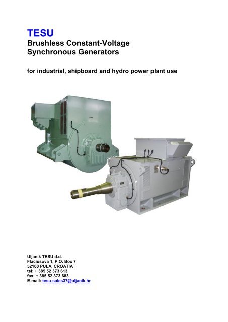
<strong>Brushless</strong> <strong>Constant</strong>-<strong>Voltage</strong><br />
<strong>Synchronous</strong> Generators<br />
for industrial, shipboard and hydro power plant use<br />
<strong>Uljanik</strong> <strong>TESU</strong> d.d.<br />
Flaciusova 1, P.O. Box 7<br />
52100 PULA, CROATIA<br />
tel: + 385 52 373 613<br />
fax: + 385 52 373 683<br />
E-mail: tesu-sales37@uljanik.hr
<strong>Brushless</strong> constant-voltage synchronous generators<br />
The <strong>Brushless</strong> <strong>Constant</strong>-<strong>Voltage</strong> <strong>Synchronous</strong> Generators are the result of our<br />
experience for some decades.<br />
Explanation of generator type design<br />
The example below shows what the generator type design mean<br />
TNC9 802 8 TNC9 indicates the generator family.<br />
When the letter J (TNJ9) stands instand of the letter C<br />
it means that the generators with protection degree<br />
IP44, IP45, water cooled i.e. provided with closed cooling system<br />
With built-in single tube or double tube water / air cooler here involved.<br />
Rating<br />
802 indicates the generator size (in B3 version it means that height<br />
from the generator support to the shaft centerline is 800 mm)<br />
8 is number of poles ( 4 means 4 poles, 6 means 6 poles, 8 means<br />
8poles, 3 means 10 poles and 5 means 12 poles)<br />
1FC(J) 1VC(J) TNC(J)9 TVC(J)9<br />
Mounting form horizontal vertical horizontal vertical<br />
Poles number 4 - 12 4 - 12 4 - 12 4 - 12<br />
Power output 145 – 5200 145 – 5200 900 – 7000 kVA 900 – 7000 kVA<br />
kVA<br />
kVA<br />
<strong>Voltage</strong> 400 – 900 V 400 – 900 V 4.16 kV – 13.8 4.16 kV – 13.8<br />
kV<br />
kV<br />
Frequency 50 Hz, 60 Hz 50 Hz, 60 Hz 50 Hz, 60 Hz 50 Hz, 60 Hz<br />
Sizes 280 – 800 280 – 800 560 – 800 560 – 800<br />
Weight 710 – 15000 900 – 17500 4400 – 16670 5300 – 20000<br />
kg<br />
kg<br />
kg<br />
kg<br />
More poles as a smaller or higher nominal powers available on special request.<br />
2
Application<br />
<strong>Brushless</strong> constant-voltage synchronous generators<br />
All <strong>TESU</strong> generators can be used as main or standby units in land based power<br />
installations, or can be used for ship's electrical systems. Internal combustion<br />
engines or gas steam and water turbines and electric motors can drive them.<br />
Construction<br />
The <strong>TESU</strong> synchronous generators are low and/or high-voltage machines. The<br />
generator comprises the main machine, exciter and excitation unit. The brushless<br />
constant-voltage synchronous generators are of the self-excited type with an<br />
automatic voltage regulator. The generators are designed for self-ventilation.<br />
Frame and stator core<br />
The stator consists of the housing with the core and windings for the main machine,<br />
exciter, end shields and bearings. The generators are fitted with top mounted<br />
excitation control unit or it is mounted separately in a box.<br />
The housing is made of steel plate. The mounting feet, which are an integral part of<br />
the housing, are designed depending on the type of construction.<br />
The output voltage terminal box may be fitted on side of the housing. The terminal<br />
box is spacious and readily accessible permitting easy and reliable connection of the<br />
cables. It is designed for degree of protection IP54.<br />
The stator core of the main machine is made of high quality both sides insulated<br />
electrical sheet steel. It is subdivided into stacks by means of ventilating ducts and<br />
spacers thus ensuring effective cooling. The complete core with windings is pressed<br />
into the housing.<br />
The exciter housed in the same generator housing is mounted on the end shield at<br />
the non-drive end.<br />
The end shields of welded structure carry the rolling or sleeve bearings assembly.<br />
Main stator winding<br />
The stator windings are made applying the most recent developments in<br />
engineering and materials. <strong>Uljanik</strong>-<strong>TESU</strong> for it's generators utilise several different<br />
insulation systems depending on voltage rating. This insulation is featured by high<br />
percentage of mica.<br />
Conductors are insulated with varnish and double layer of glass fibre of high dielectric<br />
strength. Mica type coil insulation is used. The insulation is baked under pressure so<br />
to completely eliminate air and to obtain a homogenous layer. The winding end turns<br />
are insulated with polymerised mica tape, which simultaneously gives both dielectric<br />
strength and elasticity. The final layer protects the insulation against detrimental<br />
atmospheric and chemical influences.<br />
3
<strong>Brushless</strong> constant-voltage synchronous generators<br />
Selected material and method of binding result in a strong and unified winding assembly<br />
that will withstand the large mechanical forces which appear during different generator<br />
transient fault conditions (su<strong>dd</strong>en short-circuits, loss of synchronism).<br />
Cylindrical rotor<br />
The rotor is laminated, cylindrical. The windings are placed in the semi-closed slots. They<br />
are impregnated with solvent-free resin. Such design offers the excellent mechanical<br />
properties. The rotor is fitted with a complete cage serving as damper winding.<br />
The rotor consists of the shaft, the rotor core, the field and damper windings. The shaft<br />
also carries, on the non-drive end, the rotating rectifier, the rotor core of the exciter with a<br />
three-phase winding. The shaft is fitted with fan.<br />
The rotor core of the main machine is made of electrical non-oriented sheet steels.<br />
Ventilating ducts, which are formed by spacers, subdivide the core into packets and<br />
ensure effective cooling.<br />
The field winding is arranged around the core periphery. The winding is distributed over<br />
slots per pole, which ensures that the rotating masses are uniformly distributed over the<br />
rotor circumference. Therefore the mechanical stressing due to the centrifugal forces is<br />
considerably smaller. In a<strong>dd</strong>ition to this, a uniform temperature distribution is thereby<br />
obtained, which increases the life of the winding. To make the end turns resistant to the<br />
centrifugal forces, rings of fiberglass are fitted on the overhang. For the slot insulation of<br />
rotor winding the Nomex material is used. All the connections of the winding are<br />
hardsoldered. The rotor core assembly with winding is impregnated with resin.<br />
The damper winding consists of bars, which are accommodated in equally spaced slots.<br />
At the core ends, the bars are bent and welded to end rings, thus forming a damper cage.<br />
With synchronous machines the damper winding reduces distortion of the voltage and<br />
current waves to a minimum, even under conditions of unbalanced loading. Owing to the<br />
good magnetic coupling between the stator and damper winding the effects of inducing<br />
disturbances, such as torque pulsation, which occur in some driving machines, electrical<br />
and mechanical shock loads and harmonics are effectively suppressed.<br />
The rotating rectifier comprises a full-wave three-phase rectifying bridge. The rectifier<br />
design and selected high-quality silicon elements ensure high operation safety and<br />
protect the diodes.<br />
The thermal endurance of the winding insulation of the main machine and the exciter<br />
satisfies the requirements for class F insulation. The insulation is resistant to moisture, oil<br />
vapours and sea air.<br />
4
<strong>Brushless</strong> constant-voltage synchronous generators<br />
Excitation system<br />
The mode of operation of excitation system is compound. The main stator supplies the<br />
exciter via excitation unit. The voltage regulator regulated the field current necessary to<br />
obtain constant generator voltage.<br />
Mode of operation<br />
The rotating excitation winding of the generator itself is supplied from the rotor winding of<br />
the exciter via rotating diodes in three-phase bridge connection. The stationary field<br />
winding of the exciter is supplied from the stationary excitation system. When the<br />
generator is driven, the remanent magnetism of the active iron in the stator core of the<br />
main machine produces a speed-dependent self-excitation voltage. Part of the energy<br />
thus produced is trapped of the generator terminals and taken to the field winding of the<br />
exciter via the excitation control unit. This completes the circuit in which the excitation<br />
energy flows.<br />
The excitation control unit a<strong>dd</strong>s up an generator-voltage-proportional component and an<br />
generator-current-proportional component to form an excitation current slightly higher<br />
than necessary to produce the rated voltage. The thyristor voltage regulator then keeps<br />
the generator voltage at the required level by allowing the excess excitation current to<br />
flow in a bypass to the excitation winding (buck control).<br />
The generator excitation current is controlled at a low energy level.<br />
Standards and Requirements<br />
The generators conform to applicable IEC requirements, DIN standards and VDE codes<br />
and particularly to VDE 0530, Specification for rotating electrical machines. They can also<br />
be made to comply with foreign standards and requirements.<br />
BS 2613 and 5000 part 16,<br />
NF C51-100,<br />
CSA C22.2-100<br />
CEI 2-3<br />
Other standards on enquiry<br />
The excitation equipment has been rated for compliance with Group C requirements to<br />
VDE 0660 and VDE 0110.<br />
5
Output<br />
Technical data<br />
The rated outputs (kVA) are valid for following operating conditions:<br />
-continuous running duty at 50 or 60 Hz rated frequency<br />
-power factors from 0.8 to 1,<br />
-class F insulating<br />
-sinusoidal load current<br />
-symmetrical load<br />
Site rated output<br />
The application and site conditions for the correct sizing of generator should be taken<br />
into consideration.<br />
The following factors should be taken into consideration:<br />
1. Ambient temperature<br />
The generators are designated for use under 40C ambient temperature.<br />
If coolant temperature exceeds 40C, then reduced ratings according to standard or<br />
classification society rules should be taken into consideration.<br />
The output rating can be obtained by applying the factors as in the following table.<br />
Ambient Temperature [°C] 40 45 50 55<br />
Multiply by factor 1.00 0.95 0.925 0.9<br />
2. Altitude<br />
The generators are designated for use in altitude less then 1000 m.a.s.l.<br />
In case altitude exceeds 1000 m a.s.l. then generator reduced ratings should be<br />
taken into consideration (does not apply for marine generators).<br />
Site altitude Permissible output<br />
m.a.s.l. % of rated value<br />
1000 100<br />
1500 97<br />
2000 94<br />
2500 91<br />
3000 87<br />
3500 82<br />
4000 77<br />
If no coolant temperature is stated, it will be assumed that the altitude-induced reduction in<br />
the cooling efficiency is compensated by a lower coolant temperature. i.e. that adjustment<br />
of the maximum temperature rise to VDE 0530 is not necessary (no derating).<br />
The following coolant temperatures are obtained for the thermal utilization corresponding<br />
to Class F insulation:<br />
Altitude in m a.s.l: 1000, 1500, 2000, 2500, 3000, 3500, 4000<br />
Coolant temperature in 0C: 40, 35, 30, 25, 19, 14, 9<br />
6
3. Power factor cos phi < 0,8<br />
Technical data<br />
If power factor is less than 0,8 then reduced ratings should be taken into<br />
consideration.<br />
Cos phi Permissible output<br />
% of rated value<br />
0.8 ... 1 100<br />
0.7 96<br />
0.6 92<br />
0.5 91<br />
0.4 90<br />
0.0 88<br />
<strong>Voltage</strong> and frequency<br />
The generators are available for 50 Hz or 60 Hz.<br />
Rated voltages of generators are between 400 V and 13,8 kV.<br />
The rated voltage can be standard adjusted within a range of 5%. Other voltage<br />
adjustment ranges are possible on request.<br />
Enquires are also welcomed for special voltages and for frequencies other than 50 and<br />
60 Hz.<br />
Apart from an internal reference value potentiometer on the regulator the rated voltages<br />
can be adjusted 5 % using an external panel mounting reference value setter (optional<br />
extra).<br />
The three-phase stator winding of the generators is connected in star. The neutral point<br />
is brought out.<br />
Radio interference suppression<br />
The generators are supplied with interference suppression grade N to VDE 0875,<br />
suppression level K on request.<br />
Special measures<br />
Special insulation design can be delivered where extreme exposure to water, e.g. due to<br />
flooding or prolonged condensate formation, or high concentrations of aggressive or<br />
electrolytically active media are to be expected. (Please enquire for further information).<br />
7
Block diagram<br />
A1 <strong>Voltage</strong> regulator<br />
C1…C3 Capacitor<br />
G1 Main machine<br />
G2 Exciter<br />
L1 Reactor<br />
T1…T3 Single phase current trensformer<br />
T4 Current transformer for droop compensation<br />
T6 Rectifier transformer<br />
T7…T8 <strong>Voltage</strong> transformer<br />
V1 Stationary rectifier<br />
V2 Rotating rectifier<br />
8
Types of construction<br />
Mechanical data<br />
The generators can be available in the versions according to IEC 34-7.<br />
They can be two bearing or single bearing designed. Depending on operating conditions<br />
and technical limits of bearing, generator can be available with rolling contact bearings or<br />
sleeve bearings.<br />
Degree of protection<br />
The generators normally have degree of protection IP 23 (DIN 40 050).<br />
The terminal box has degree of protection IP 54.<br />
Other degrees of protection are available on request.<br />
Speed and direction of rotation<br />
The generator speed is defined to meet the requirements of the prime mover. At the rated<br />
speed the generator produces the rated frequency of 50 Hz or 60 Hz. The generators are<br />
made for clockwise or anti-clockwise running when viewed from the drive end.<br />
Overspeed for generator is nmax= 1,2 x nn<br />
Higher values are possible on request.<br />
Air filter<br />
An air filter can be fitted for special conditions (on request).<br />
Anti-condensation heating<br />
Anti-condensation heating is available for the generators (on request).<br />
The anti-condensation heater requires a voltage of 220 V or 110V and has heat output of<br />
about 315 W to 630W:<br />
Terminals and connection bus-bars<br />
Main terminal box is available with one terminal box which comprises 4 main connections,<br />
(U, V, W, N) or two terminal boxes which comprise 6 main connections (U1, U2, V1, V2,<br />
W1, W2).<br />
Paint finish<br />
The generators are supplied with a priming coat. Standard paint finish in RAL 7030 or<br />
other colours or special paint finish can be provided at extra cost.<br />
9
Cooling<br />
Mechanical data<br />
The generators are internally air cooled by shaft-mounted fan (IC 01). The fan provided at<br />
the drive-end draws the cooling air axially through the machine.<br />
Drive and coupling<br />
The generators provided with two bearings can be driven by reciprocating engines via<br />
flexible shaft couplings.<br />
The coupling is not part of the scope of delivery of the generator manufacturer.<br />
The torsional vibration has to be calculated for rigidly coupled single-bearing generators.<br />
For this purpose, a preliminary generator and shaft dimension sheet is made available.<br />
Types of construction<br />
The generators can be supplied in the following versions to IEC 34-7. IM = international<br />
mounting. DIN 42 950 designations are in brackets.<br />
For information about the different types of construction with extra or reduced prices refer<br />
to the price list or please enquire.<br />
Generators sizes 284 to 354 can be easily adapted to various mounting situations by the<br />
feet mountings on the housing. They can also be supplied without feet (reduced price).<br />
If requested, flange dimensions other than those quoted in the dimensions tables can be<br />
supplied (extra price). Please give flange diameter N and flange depth R.<br />
10
Performance data<br />
Behaviour under steady-state conditions<br />
The generators in the new range are particularly good at meeting the requirement for<br />
stable voltage control throughout the load range. The steady-state deviation from the<br />
rated voltage is not greater than 0.5% anywhere in the range from no-load to full load.<br />
The usual speed increase of the prime mover on change over from rated load to no load<br />
does not affect the accuracy stated. The setpoint potentiometer included in the voltage<br />
regulator or an external panel-mounting potentiometer permits the generator voltage to be<br />
adjusted within a range of 5% of the rated voltage. In the event of faults in the regulating<br />
system, the generator voltage never rises beyond 115% of the rated voltage owing to the<br />
buck control principle adopted for the excitation system. The excitation system can supply<br />
a sustained short-circuit current of three to five times the rated current; this enables the<br />
use of graded protective relaying.<br />
A speed-proportional voltage is produced during run-up of the generator from the<br />
nonexcited condition or during operation at less than rated speed and the excitation<br />
current does not rise beyond the permissible values. This precludes the risk of thermal<br />
damage to the excitation winding even at less than rated speed.<br />
Dynamic behaviour<br />
The excitation system and a carefully matched electromagnetic design of the main and<br />
exciter machines together make for highly satisfactory dynamic voltage control behaviour.<br />
With the phase shift between the current and voltage corresponding to 0.8 p.f. the<br />
transient voltage reduction or increase on connection or disconnection of rated load is<br />
only about 15%. This value is largely determined by the subtransient reactance of the<br />
main machine, i.e. by the leakage inductance of the windings. The settling time is shorter<br />
than 500 ms. With the command variable (load current) closely coupled to the output<br />
variable (excitation current) by compound excitation, this generator responds to su<strong>dd</strong>en<br />
load changes much faster than a generator with ordinary closed-loop control.<br />
Because in the excitation system the controller only needs to correct the difference<br />
between the setpoint value and the value defined by compounding, the favorable effect of<br />
compounding is retained in full.<br />
Parallel operation<br />
Stable parallel operation is ensured by:<br />
- damper winding, which counteracts phase swinging,<br />
- the quadrature-droop device included in the excitation control unit to ensure equal<br />
reactive-load sharing and,<br />
- the setting of the speed controllers of the prime movers for appropriate sharing of<br />
the active power, this being within the sphere of responsibility of the supplier of the<br />
prime movers.<br />
11
Performance data<br />
The quadrature-droop device consists of a current transformer and a droop potentiometer<br />
included in the voltage regulator. A reactive current dependent voltage is a<strong>dd</strong>ed to the<br />
voltage signal representing the actual generator voltage. This a<strong>dd</strong>ition to the actual-value<br />
voltage causes the voltage regulator to linearly reduce the generator voltage by a preset<br />
droop percentage in a manner depending on the reactive current output. At zero power<br />
factor and rated power the voltage reduction amounts to 6% of the rated voltage.<br />
With the same voltage droop settings the generators thus equipped can be operated in<br />
parallel without any limits set by the reactive load sharing and by the risk of phase<br />
swinging.<br />
Unbalanced Load<br />
The generators can withstand unbalanced loading of up to 20%.<br />
Overload<br />
In accordance with IEC 34-1, the generators can have an overload of 1.5 times the rated<br />
current at rated voltage for 30 sec.<br />
Sustained short-circuit current<br />
The excitation unit used is designed to withstand a sustained three-phase short-circuit<br />
current of 3 to 5 times the rated current for a period of 3 seconds. This enables the use of<br />
selective protection systems.<br />
Generator protection equipment<br />
The stator winding can be provided with thermal protection in the form of PTC sensors or<br />
resistance thermometers PT 100 (on request)<br />
The necessary monitoring and tripping devices must be provided separately and are not<br />
included in the generator scope of supply.<br />
12
Special provisions for marine generators<br />
In a<strong>dd</strong>ition to satisfying the standards and codes the marine generators also conform<br />
to the requirements of the following classification societies:<br />
Classification society Abbreviation Coolant temperature (CT) 0C<br />
American Bureau of Shipping ABS 50<br />
Bureau Veritas BV 40,45, 50<br />
Germanischer Lloyd GL 40, 45<br />
Lloyd's Register of Shipping LRS 40, 45, 50<br />
Det Norske Veritas NV 35, 45<br />
Registro Italiano Navale RINa 45, 50<br />
Marine generators can also be supplied to satisfy the requirements of other<br />
classification societies such as<br />
Polski Rejestr Statkow PRS<br />
USSR Register of Shipping<br />
U.S.Coast Guard<br />
Register of Shipping of P.R. of China<br />
With generators to be operated as shaft generators (driven from the main engine or<br />
turbine) attention must be paid to the special speed characteristic and, if applicable,<br />
to the excess-torque protection. Please enquire for further information.<br />
Works inspection and acceptance<br />
All marine generators are subject to works inspection and acceptance as stipulated in<br />
the Table below:<br />
Classification society Works<br />
Acceptance<br />
Abbreviation<br />
inspection<br />
ABS ≥100 kW ≥100 kW<br />
BV ≥100 kW All<br />
GL - ≥50 kW<br />
LRS,RINa ≥100 kW ≥100 kW<br />
NV all all<br />
Generators intended for use on a ship's propulsion system are subject to works<br />
inspection and acceptance testing, irrespective of the output rating.<br />
13
Overload requirements<br />
Special provisions for marine generators<br />
Rules Overload current Overload Remarks<br />
In % of rated current duration<br />
VDE 150 2 min -<br />
ABS -<br />
- no overload capability<br />
specified<br />
125<br />
2 h*) only at owner's request.<br />
Steady-state temperature<br />
Rise from previous<br />
operation not to be more<br />
than 15K<br />
BV 150 2 min at p.f. 0.6 (lagging)<br />
GL 150 2 min at p.f. 0.5 (lagging)<br />
LRS 150 15 s -<br />
NV 150 2 min Only for lternators<br />
At p.f. 0.6 and rated<br />
frequency<br />
RINa 150 2 min at p.f. 0.6 (lagging)<br />
During overload the voltage must be kept as nearly as possible at its rated value.<br />
*) The rated output given in the Selection Tables is to be reduced to 88 %.<br />
Air/water cooler<br />
If required, the generators can be supplied with a top-fitted air/water cooler.<br />
The cooler can be used for freshwater or salt water and can be of the single-tube or<br />
double-tube type.<br />
The type designation for the generators is changed from 1FC to 1FJ. Due to the closedcircuit<br />
cooling system the degree of protection has been upgraded from IP 23 to IP 54.<br />
The electrical version of the generator remains unchanged.<br />
The generators 1FJ can easily be converted for emergency operation as an open-circuit<br />
aircooled machine if the coolant system or the cooling element fails. In this case, the<br />
degree of protection is IP 23 with the rated output unaltered.<br />
The rated output of the generator type chosen thus corresponds to the values in the<br />
Selection Tables with the associated coolant temperature.<br />
Please provide the following information with any enquiry:<br />
- Generator rated output<br />
- Classification society<br />
- Coolant temperature (air)<br />
- Cooling water inlet temperature<br />
- Freshwater or seawater<br />
- Single-tube or double-tube cooler<br />
The exact dimension of the cooler and the height of the generator will be defined in case<br />
of order.<br />
14
Classification society rules<br />
Special provisions for marine generators<br />
Classification Anti-condensation Thermometer<br />
Society heating *)<br />
Temperature sensor<br />
ABS For generators with a total Resistance thermometer to measure the<br />
weight (less shatt) of more stator winding temperature for<br />
than 1000 Ibs ( = 450 kg) generators above 500 kVA<br />
GL From 500 kVA Temperature sensors in the stator<br />
winding for generators with air filters;<br />
thermometer in the cooling air circuit and<br />
a temperature sensor in the stator<br />
winding for generators with air/water<br />
cooler;<br />
bearing thermometer for sleeve<br />
bearings;<br />
alarm device for excessive temperature<br />
of bearings with external lubrication.<br />
LRS From 400 kW Temperature sensor in the cooling air<br />
circuit for generators with air/water<br />
cooler<br />
*) We always recommend that generators for emergency and port use be ordered with<br />
anti-condensation heating, regardless of the classification society rules.<br />
Spare parts<br />
Classification societies generally call for the following spare parts:<br />
Spare parts<br />
Classification society<br />
ABS BV GL LRS DNV RINa<br />
1 set rolling-contact bearings<br />
(bearing shells for sleeve bearings)<br />
<br />
1/3 rectifier assembly <br />
1 electronic voltage regulator <br />
1 set brush holder <br />
1 set brush spare parts <br />
1 set of special tools <br />
Regardless of the requirements made by the classification societies we recommend<br />
that the spare parts be ordered together with the generators.<br />
15