Excitation Control System Design of Superconducting ... - PSCC
Excitation Control System Design of Superconducting ... - PSCC
Excitation Control System Design of Superconducting ... - PSCC

Create successful ePaper yourself
Turn your PDF publications into a flip-book with our unique Google optimized e-Paper software.
4.4 SMES effect as Load Model<br />
The second constraint to be considered in excitation<br />
control system design is SMES effect. As shown in<br />
section (3.2) that SMES effect is considered as a<br />
nonlinear load with current flowing out <strong>of</strong> the generator<br />
terminal as given in (2), the variation <strong>of</strong> those currents<br />
can be obtained as shown in (18).<br />
⎡∆I<br />
⎢<br />
⎣<br />
∆I<br />
exD<br />
exQ<br />
⎤ ⎪⎧<br />
− 2 ⎡ Pex<br />
⎥ = ⎨ ⋅ 4 ⎢<br />
⎦ ⎪⎩<br />
V ⎣−<br />
Q<br />
t0<br />
0<br />
ex0<br />
Q<br />
P<br />
ex0<br />
ex0<br />
2<br />
⎤⎡<br />
VD0<br />
⎥⎢<br />
⎦⎢⎣<br />
VD0V<br />
Q0<br />
V<br />
V<br />
D0<br />
Q0<br />
2<br />
VQ0<br />
1 ⎡ P ⎤⎪⎫<br />
⎡∆V<br />
ex0<br />
Qex0<br />
D ⎤<br />
+ 2 ⎢<br />
⎥⎬⎢<br />
⎥<br />
V ⎣−<br />
Q ⎦⎪⎭<br />
⎣<br />
∆V<br />
t ex0<br />
P<br />
0<br />
ex0<br />
Q ⎦<br />
1 ⎡VD<br />
0 ⎤ 1 ⎡ VQ0<br />
⎤<br />
+ ⎢ Pex<br />
∆Qex<br />
V V<br />
⎥∆<br />
+ ⎢<br />
t Q V V<br />
⎥<br />
(18)<br />
2<br />
2<br />
⎣ 0 ⎦<br />
t ⎣−<br />
0<br />
0 D0<br />
⎦<br />
Since Pex can be evaluated in terms <strong>of</strong> generator<br />
variables as shown in (1), the variation <strong>of</strong> excitation<br />
power can be determined by (19).<br />
∆ = +<br />
(19)<br />
Pex v f 0∆i<br />
f i f 0∆v<br />
f<br />
∆if and ∆vf are considered as state variables <strong>of</strong><br />
generators (SCG). SMES effect in the form <strong>of</strong> current<br />
can be considered by combining (19) into (18), the<br />
state-matrix <strong>of</strong> power system in (9) and (10) are<br />
evaluated to determine the eigenvalues and eigenvalue<br />
sensitivity based parameter optimization method is<br />
employed to determine optimal control parameters.<br />
As for Qex, it can be adjusted by AC-DC converter<br />
according to the external control signal value (such as<br />
what is shown in the next section). It can be set to be<br />
zero when no control is applied for this value.<br />
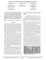
4.5 Reactive Power <strong>Control</strong> (Qex -<strong>Control</strong>)<br />
As described in (4.4) that Qex can be adjusted by<br />
AC-DC converter according to external control signal.<br />
In order to support and improve voltage stability, here,<br />
the simple control system in the form <strong>of</strong> the 1 st order<br />
time-lag transfer function control block with bus<br />
voltage input as shown in Fig. 5 is applied to control<br />
reactive power <strong>of</strong> SMES effect. Mathematical<br />
expression <strong>of</strong> the controller is shown in (20).<br />
Vt<br />
( − ∆Q<br />
+ K ( V V ) )<br />
Q& 1<br />
− (20)<br />
∆ ex =<br />
ex q t0<br />
Tq<br />
Vt0<br />
-<br />
+<br />
K<br />
q<br />
1 + T<br />
Figure 5: Reactive power controller<br />
q<br />
s<br />
t<br />
∆Qex<br />
5 NUMERICAL EXAMPLES<br />
The digital simulations are conducted in two model<br />
power systems, which are IEEJ East 10-machine and<br />
West 10-machine systems, to examine the performance<br />
<strong>of</strong> the proposed excitation control systems <strong>of</strong> SCG with<br />
high response excitation. In each model system, for one<br />
⎤<br />
⎥<br />
⎥⎦<br />
pattern <strong>of</strong> replacing one conventional generator (CG) by<br />
one SCG whose parameters shown in Table 1, five<br />
cases <strong>of</strong> different generator types, excitation modes<br />
(operation), and excitation control schemes as shown in<br />
Table 2 are considered. In cases 2~5, excitation control<br />
systems are PSS-AVR (Qex-<strong>Control</strong> is added only in<br />
case 5) whose parameters determined by the eigenvalue<br />
sensitivity based parameter optimization method.<br />
Table 1: Parameters <strong>of</strong> SCG with high response excitation<br />
d-axis synchronous reactance Xd 0.40 [p.u.]<br />
d-axis transient reactance X ’ d 0.30 [p.u.]<br />
d-axis subtransient reactance X ’’ d 0.20 [p.u.]<br />
q-axis synchronous reactance Xq 0.40 [p.u.]<br />
q-axis subtransient reactance X ’’ q 0.20 [p.u.]<br />
Leakage reactance Xl 0.15 [p.u.]<br />
d-axis transient open circuit time constant T ’ do 100 [sec]<br />
d-axis subtransient open circuit time constant T ’’ do 0.03 [sec]<br />
q-axis subtransient open circuit time constant T ’’ qo 0.03[sec]<br />
Inertia constant H 5 [sec]<br />
Damping coefficient D 0 [p.u.]<br />
Table 2: Generator types and control schemes<br />
Case Machine Operation <strong>Excitation</strong> <strong>Control</strong> <strong>System</strong><br />
1 CG Separately AVR<br />
2 CG Self PSS-AVR<br />
3 SCG Separately PSS-AVR<br />
4 SCG Self PSS-AVR<br />
5 SCG Self PSS-AVR + Qex-<strong>Control</strong><br />
5.1 IEEJ East 10-machine <strong>System</strong><br />
The model system consisting <strong>of</strong> 10 generators and 47<br />
buses is shown in Fig. 6. The structure <strong>of</strong> the system is<br />
a loop network with radial line connected at node 17.<br />
Three patterns <strong>of</strong> replacement <strong>of</strong> conventional generator<br />
by SCG with high response excitation at nodes 2, 5, and<br />
10 are taken into account. <strong>Excitation</strong> control systems for<br />
each pattern are designed and eigenvalues <strong>of</strong> power<br />
system are evaluated; only dominant eigenvalues are<br />
considered and shown in Table 3.<br />
10 <br />
20<br />
G10<br />
<br />
37 36<br />
<br />
<br />
47 19<br />
18<br />
<br />
<br />
<br />
<br />
9<br />
8<br />
G9<br />
G1 G2 G4<br />
1 2<br />
4<br />
11<br />
<br />
<br />
12<br />
<br />
14<br />
<br />
17<br />
<br />
16<br />
G3 G5 <br />
<br />
13<br />
10 <br />
<br />
5<br />
15<br />
<br />
<br />
<br />
<br />
25 26 28 31 <br />
35<br />
21 23 29 32<br />
<br />
44<br />
<br />
45<br />
<br />
46<br />
<br />
22 24 27 30 33 <br />
34<br />
<br />
<br />
G8<br />
<br />
G7<br />
7<br />
38 39 40 41 42 43<br />
Figure 6: IEEJ East 10-machine system<br />
As shown in Table 3, comparing with case 1, when<br />
PSS-AVRs are designed by employing eigenvalue<br />
sensitivity based parameter optimization method for<br />
generators, it can be seen that damping <strong>of</strong> system is<br />
improved well in all patterns and all cases. When CG is<br />
replaced by SCG in cases 3~5, there are some cases that<br />
damping <strong>of</strong> one mode is improved but the other is not<br />
15th <strong>PSCC</strong>, Liege, 22-26 August 2005 Session 28, Paper 1, Page 4<br />
6<br />
G6