millcentric® eccentric plug valve - Milliken Valve Company
millcentric® eccentric plug valve - Milliken Valve Company
millcentric® eccentric plug valve - Milliken Valve Company

Create successful ePaper yourself
Turn your PDF publications into a flip-book with our unique Google optimized e-Paper software.
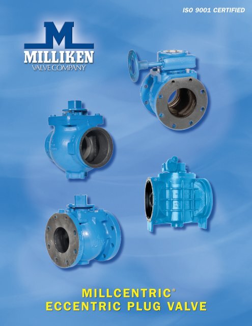
MILLCENTRIC ®<br />
ECCENTRIC PLUG VALVE<br />
ISO 9001 CertIfIed
<strong>Milliken</strong> <strong>Valve</strong> offers the following for<br />
your water and wastewater needs:<br />
• Eccentric Plug <strong>Valve</strong>s<br />
~ Series 601/600 Flanged & MJ<br />
~ Series 601S Stainless Steel<br />
~ Series 601RL Rubber Lined<br />
~ Series 602 High Pressure<br />
~ Series 603 Threaded End<br />
~ Series 604E Three Way<br />
~ Series 606 Grooved End<br />
~ Series 611/610 Flanged & MJ<br />
~ Model 625 UL /CGA Listed<br />
• AWWA Swing Check <strong>Valve</strong>s<br />
• Wafer Check <strong>Valve</strong>s<br />
• Flex Check<br />
• Spring Loaded Check <strong>Valve</strong>s<br />
• AWWA Butterfly <strong>Valve</strong>s<br />
• General Service Butterfly <strong>Valve</strong>s<br />
The <strong>Milliken</strong> <strong>Valve</strong> <strong>Company</strong> designs, develops, manufactures<br />
and markets <strong>plug</strong>, butterfly, and check <strong>valve</strong>s and their<br />
respective controls and actuators. These <strong>valve</strong>s are used<br />
primarily in the water, wastewater, and industrial markets.<br />
<strong>Milliken</strong> <strong>Valve</strong> was started over two decades ago manufacturing the<br />
<strong>eccentric</strong> <strong>plug</strong> <strong>valve</strong> for the waste water and HVAC marketplace.<br />
Growth has been constant with the addition of a AWWA butterfly<br />
<strong>valve</strong>, general service butterfly <strong>valve</strong>, swing check <strong>valve</strong>, rubber<br />
flapper check <strong>valve</strong>, double disc check <strong>valve</strong>, wafer (outside spring)<br />
check <strong>valve</strong>, globe style check <strong>valve</strong> and compact wafer check <strong>valve</strong>.<br />
<strong>Milliken</strong> believes that in order to satisfy customers, our products<br />
need to be considered the best design and the highest quality within<br />
the industry. All of our <strong>valve</strong>s have had extensive testing before they<br />
are marketed or sold. <strong>Milliken</strong>’s quality standards are a step above<br />
the industry norm, and <strong>Milliken</strong> is committed to standing behind its<br />
products in the field. All <strong>valve</strong>s are tested in complete conformance<br />
to applicable standards before shipment. In addition, <strong>valve</strong> designs<br />
are routinely sent to independent testing facilities to ensure they<br />
meet or exceed expectations.
Millcentric Eccentric Plug <strong>Valve</strong><br />
Suggested Specifications ........................................................................................2-3<br />
Technical Data...........................................................................................................4<br />
Standard Materials of Construction, Fig. 601/600, 12" & Smaller .........................5<br />
Standard Materials of Construction, Fig. 601/600, 14" & Larger ..........................6<br />
Flanged End, Fig. 601 Cast Iron / 611 Ductile Iron 2 1 ⁄2" – 12" ............................7<br />
Mechanical Joint, Fig. 600 Cast Iron / 610 Ductile Iron 3" – 12" .........................8<br />
Larger Flanged End, Fig. 601 Cast Iron / 611 Ductile Iron and Mechanical Joint<br />
End, Fig. 600 Cast Iron / 610 Ductile Iron 14" & Larger ......................................9<br />
Flanged End Fig. 602 Class 250 2 1 ⁄2" & Larger ....................................................10<br />
Flanged End, Fig. 601RL Rubberlined 3" & Larger ............................................11<br />
Grooved End, Fig. 606 2 1 ⁄2" – 20" .........................................................................12<br />
Adaption ..................................................................................................................13<br />
Technical Specification Series 601/600 Cast Iron <strong>Valve</strong>s ......................................14<br />
Technical Specification Series 602 Class 250 <strong>Valve</strong>s .............................................15<br />
Technical Specification Series 601RL Rubberlined <strong>Valve</strong>s ..................................16<br />
Technical Specification Series 601S Stainless Steel <strong>Valve</strong>s ...................................17<br />
Technical Specification Series 611/610 Ductile Iron <strong>Valve</strong>s .................................18<br />
Technical Specification Series 601GL Glass Lined <strong>Valve</strong>s ...................................19<br />
page 1
Suggested Specifications<br />
The <strong>Milliken</strong> criteria of quality, reliability, safety and<br />
value are embodied in the Millcentric ® Eccentric<br />
<strong>valve</strong>, setting higher standards for dependable<br />
performance with excellent features achieved by the<br />
utilization of the very latest design and manufacturing<br />
techniques.<br />
~ Computer Aided Design<br />
~ High Integrity Casting<br />
~ CNC manufacturing delivers consistent sizes on all<br />
components<br />
All complemented by rigorous Quality Control<br />
System<br />
Body<br />
Conforming to AWWA C504 wall thickness, the<br />
MILLCENTRIC <strong>valve</strong> body casting is in ASTM<br />
A126 CL B cast iron using high pressure molding<br />
techniques. Alternative flanged, grooved or<br />
mechanical joint ends are available.<br />
Flange diameter, thickness and drilling conform to<br />
ANSI B16.1 Class 125 or 250.<br />
Grooved ends meet AWWA C-606 for ductile or<br />
steel pipe. Mechanical joints to AWWA C111 (ANSI<br />
A21.11).<br />
Seat<br />
The MILLCENTRIC <strong>valve</strong> incorporates as standard,<br />
on 3" and larger, a 1 ⁄8" thick welded 99% nickel seat<br />
for corrosion and erosion resistance specifically<br />
profiled for low torque and extended seat life.<br />
Stem Seal<br />
High integrity sealing by combining the advantages<br />
of a resilient and abrasion resistant U-Cup seal. From<br />
vacuum to high pressure, the self-adjusting sealing<br />
system (per AWWA C504) gives positive, trouble-free<br />
service and is retained independently of the <strong>plug</strong><br />
stem or external torque device, therely eliminating<br />
periodic maintenance.<br />
Bearings<br />
The <strong>plug</strong> rotates in permanently lubricated 316<br />
grade stainless steel bearings, located in the body<br />
and bonnet, along with upper and lower PTFE thrust<br />
washers, which ensure consistently low operating<br />
torque.<br />
page 2<br />
Plug<br />
Supported on integral trunnions, the <strong>plug</strong> is totally<br />
encapsulated with an elastomer that is molded on<br />
2 1 ⁄2" – 48" and vulcanized on 54" and larger to the<br />
casting providing tight shut off even under vacuum<br />
conditions. High integrity corrosion-free sealing is<br />
achieved by a variety of abrasion resistant elastomers<br />
which protect the <strong>plug</strong> right up to the trunnions.<br />
When assembled, the light compression of the<br />
elastomers onto PTFE thrust washers, prevents entry<br />
of abrasive materials into the bearings.<br />
Bonnet Seal<br />
Superior “O” ring sealing with metal/metal contact<br />
means lower bolting stresses compared with<br />
compression gaskets.<br />
Flow<br />
The port design (round on 2 1 ⁄2" – 12" and rectangular<br />
on 14" and larger) with streamlined internal contours<br />
gives the highest industry capacity straight through<br />
flow in the full open position, reducing turbulence<br />
and pressure drop and the effect of erosive media.<br />
Handling of sludges and slurries is therefore<br />
enhanced.<br />
Interchangeable<br />
Because of the common face to face dimension with<br />
wedge gate <strong>valve</strong>s (3" – 12"), fitting the tight shut-off<br />
rotary MILLCENTRIC <strong>valve</strong> into existing systems is<br />
accomplished without pipeline modifications.<br />
Travel Stops<br />
Adjustable open and closed travel stops are fitted<br />
as standard on both wrench and gear operated<br />
MILLCENTRIC <strong>valve</strong>s.
Suggested Specifications<br />
! <strong>Valve</strong> in closed<br />
position for bubble<br />
tight shut-off<br />
! Normal flow direction<br />
gives pressure<br />
assisted sealing<br />
! Torques are low even<br />
in reverse flow<br />
Installation<br />
The Millcentric ® <strong>plug</strong> <strong>valve</strong> is suitable for<br />
flow and shut-off in either direction. Seat end<br />
downstream is the preferred orientation and any<br />
reverse flow requirement should be stated at the<br />
time of order. For use on fluids with suspended<br />
solids, installation with the seat upstream and<br />
the <strong>valve</strong> stem horizontal is recommended<br />
with, <strong>plug</strong> rotation to the top of the <strong>valve</strong><br />
will ensure smooth operation.<br />
In-Line Maintenance<br />
In the unlikely event of stem<br />
leakage, the stem seals can be<br />
easily replaced without removing<br />
the bonnet. Access to the body<br />
for cleaning or inspection does<br />
not require removal from the line.<br />
! Plug rotates away<br />
from the seat for<br />
instant opening<br />
! Seat wear and<br />
operating torque<br />
reduced<br />
! No further seat<br />
contact until <strong>valve</strong><br />
is closed again<br />
Modular Construction<br />
Design of the bonnet and stem<br />
allows for on-site adaption of<br />
gear operators, power actuators, or<br />
extension devices on to standard <strong>valve</strong>s.<br />
Conversion can be easily undertaken<br />
without removing the <strong>valve</strong> bonnet, thereby<br />
minimizing downtime.<br />
Power Operation<br />
Pneumatic, electric or hydraulic operation is<br />
available, complete with accessories such as limit<br />
switches, solenoid <strong>valve</strong>s and positioners when<br />
required.<br />
! Design of Millcentric<br />
<strong>plug</strong> <strong>valve</strong> allows<br />
modulating control<br />
over the full 90˚ travel<br />
! Ideally suited for<br />
balancing service<br />
! Standard rotary <strong>valve</strong><br />
provides control<br />
and tight shut off<br />
in one <strong>valve</strong><br />
! Plug is out of flow<br />
path when fully open<br />
! Straight through,<br />
uninterrupted<br />
smooth flow<br />
! Round port reduces<br />
turbulence and<br />
erosion, lowers<br />
pumping costs and<br />
can be “pigged” to<br />
clean the pipeline<br />
page 3
Technical Data<br />
ORDERING INFORMATION<br />
<strong>Valve</strong> Types Designation<br />
Mechanical Joint Cast Iron 600<br />
Mechanical Joint Ductile Iron 610<br />
ANSI 125 Flanged Cast Iron 601<br />
ANSI 125 Flanged Ductile Iron 611<br />
ANSI 150 Flanged Ductile Iron 621<br />
ANSI 250 Flanged Ductile Iron 602<br />
ANSI 125 Grooved for Steel Pipe 606S<br />
ANSI 125 Grooved for Ductile Pipe 606D<br />
ANSI 150 Flanged 316SS<br />
SEAT<br />
601S<br />
Nickel (3" & Larger) N<br />
Epoxy (21 ⁄2" ONLY) E<br />
316SS (on stainless steel <strong>valve</strong> only) S<br />
Rubberlined RL<br />
Glasslined<br />
ELASTOMER TRIM<br />
GL<br />
EPDM 0<br />
Buna-Nitrile 1<br />
Viton 2<br />
Neoprene 3<br />
Natural<br />
MANUAL OPERATORS<br />
4<br />
Above Ground Gear and Handwheel AGHW<br />
Above Ground Gear with 2" Nut AGNUT<br />
Buried Gear with 2" Nut BG<br />
Memory Stop Gear with Handwheel MGHW<br />
Lever / Wrench (8" & smaller) L<br />
Direct Nut (8" & smaller) TC<br />
Example: 4" 601N3AGHW = 4" ANSI 125 Flanged, Nickel Seat, Neoprene <strong>plug</strong> with<br />
Above Ground Gear and Handwheel<br />
<strong>Valve</strong>s are only tested for bi-directional shut-off if specified at time of<br />
order. Contact <strong>Milliken</strong> for bi-directional ratings.<br />
NOTE: We recommend mechanical joint or buried flanged <strong>valve</strong>s to have<br />
gear operators<br />
NOTE: We recommend <strong>valve</strong>s for bi-directional service to have gear<br />
operators<br />
Elastomer Selection Chart<br />
Service Elastomer Average Useful<br />
Temp. Range<br />
page 4<br />
Service Elastomer Average Useful<br />
Temp. Range<br />
PRESSURE RATING<br />
12" and smaller ANSI 125 175 psi<br />
14" and larger ANSI 125 150 psi<br />
20" and smaller ANSI 150 285 psi<br />
12" and smaller ANSI 250 400 psi<br />
14" and larger ANSI 250 300 psi<br />
Body Hydrotest = 150% of rated pressure / Seat Test = 100% of rated pressure<br />
Testing per AWWA C517<br />
ELASTOMERS AVAILABLE FOR<br />
MILLCENTRIC VALVE<br />
Natural rubber is also available.<br />
Nitrile<br />
A general purpose material sometimes referred<br />
to as BUNA-N or HYCAR with a –20°F to 212°F<br />
temperature range. Used on sewage, water,<br />
hydrocarbon and mineral oils.<br />
EPDM<br />
An excellent polymer for use on chilled water through<br />
to LP steam applications having a temperature range<br />
of –35°F to 250°F. Resistance to many acids, alkalies,<br />
detergents, phosphate esters, alcohols and glycols is<br />
an added benefit.<br />
Neoprene<br />
This versatile material shows outstanding resistance<br />
to abrasion and ozone. Chemical resistance to a wide<br />
range of petroleum base products and dilute acids<br />
and alkalies. Temperature range –20°F to 225°F.<br />
Viton<br />
Retention of mechanical properties at high<br />
temperature is an important feature of this elastomer:<br />
temperature range is –10°F to 300°F. It also has<br />
excellent resistance to oils, fuels, lubricants and most<br />
mineral acids and aromatic hydrocarbons.<br />
Note: Not for water or steam applications.<br />
NOTE: Above elastomer/temperature chart are guidelines only. See <strong>Milliken</strong> Compatibility Chart for specific applications.<br />
Service Elastomer Average Useful<br />
Temp. Range<br />
Acetone EPDM –35°F to 250°F Caustic Soda EPDM –35°F to 250°F Oil, Animal Nitrile –20°F to 212°F<br />
Air EPDM –35°F to 250°F Cement Slurry EPDM –35°F to 250°F Oil, Mobil Therm Light Viton 10°F to 250°F<br />
Air w/Oil Nitrile 0°F to 212°F Copper Sulphate EPDM –35°F to 250°F Oil, Mobil Therm 600 Viton 10°F to 250°F<br />
Alcohol AMYL EPDM 0°F to 212°F Creosote (Coal) Nitrile –20°F to 212°F Oil, Mobil Therm 603 Nitrile –20°F to 212°F<br />
Alcohol Aromatic Viton 10°F to 250°F Coal Slurry Nitrile –20°F to 212°F Oil, Lubricating Nitrile –20°F to 212°F<br />
Alcohol Butyl Neoprene –20°F to 225°F Diesel Fuel No. 3 Nitrile –20°F to 212°F Oil, Vegetable Nitrile –20°F to 212°F<br />
Alcohol Denatured Nitrile –20°F to 212°F Diethylene Glycol EPDM –35°F to 250°F Paint, Latex Nitrile –20°F to 212°F<br />
Alcohol Ethyl EPDM –20°F to 250°F Ethylene Glycol EPDM –35°F to 250°F Phosphate Ester EPDM –35°F to 250°F<br />
Alcohol Grain Nitrile –20°F to 212°F Fatty Acid Nitrile –20°F to 212°F Propane Nitrile –20°F to 212°F<br />
Alcohol Isopropyl Neoprene –20°F to 225°F Fuel Oil No. 2 Nitrile –20°F to 212°F Rape Seed Oil EPDM –35°F to 250°F<br />
Alcohol Methyl EPDM –20°F to 250°F Fertilizer Liquid H4N2O2 EPDM –35°F to 250°F Sewage with Oils Nitrile –20°F to 212°F<br />
Ammonia Anhydrous Neoprene –20°F to 225°F Gasoline Keg Nitrile –20°F to 212°F Sodium Hydroxide 20% EPDM –35°F to 250°F<br />
Ammonium Nitrate EPDM –20°F to 250°F Gas Natural Nitrile –20°F to 212°F Starch EPDM –35°F to 250°F<br />
Ammonia, water EPDM –20°F to 250°F Glue, Animal Nitrile –20°F to 212°F Steam to 250°F EPDM –35°F to 250°F<br />
Animal Fats Nitrile –20°F to 212°F Green Liquor EPDM –20°F to 212°F Stoddard, Solvent Nitrile –20°F to 80°F<br />
Black Liquor EPDM –20°F to 250°F Hydraulic Oil (Petro) Nitrile –20°F to 212°F Sulphuric Acid 10% 50% Neoprene –20°F to 158°F<br />
Blast Furnace Gas Neoprene –20°F to 225°F Hydrogen Nitrile –20°F to 212°F Sulphuric Acid 100% Viton 10°F to 300°F<br />
Butane Nitrile –20°F to 212°F JF4, JP5 Viton –20°F to 212°F Trichloroethylene Dry Viton 10°F to 300°F<br />
Bunker Oil “C” Nitrile –20°F to 212°F Kerosene Nitrile 0°F to 212°F Triethanol Amine EPDM –35°F to 250°F<br />
Calcium Chloride EPDM –20°F to 250°F Ketone EPDM –35°F to 250°F Varnish Viton 10°F to 300°F<br />
Carbon Dioxide EPDM –20°F to 250°F Lime Slurry EPDM –35°F to 250°F Water, Fresh EPDM –35°F to 250°F<br />
Carbon Monoxide (Cold) Neoprene –20°F to 150°F Methane Nitrile –20°F to 212°F Water, Salt EPDM –35°F to 250°F<br />
Carbon Monoxide (Hot) Viton 10°F to 300°F Methyl Ethyl Ketone EPDM –35°F to 250°F Xylene Viton 10°F to 300°F<br />
Carbon Tetrachloride Viton 10°F to 300°F Naptha (Berzin) Nitrile –20°F to 212°F
Standard Materials of Construction, Fig. 601/600, 12" & Smaller<br />
Item No. Component Material<br />
1 Body Cast Iron A126 Class B<br />
2 Plug Rubber Coated Ductile Iron<br />
ASTM A536<br />
3 Cap Cast Iron A126 Class B<br />
4 Torque Collar Ductile Iron ASTM A536<br />
5 Journal Bearing St.Steel — ANSI 316<br />
6 PTFE Washer (Grit Seal) PTFE<br />
7 O Ring Elas. as Spec.<br />
8 U Cup Seal Elas. as Spec.<br />
9 Washer Brass — ASTM B-138-675<br />
10 Internal Snap Ring Spring Steel<br />
11 Setscrew Steel (Zinc Plated)<br />
12* Closed Stop Steel (Zinc Plated)<br />
13* Locking Washer Steel<br />
14* Nut Steel (Zinc Plated)<br />
15* Open Stop Steel (Zinc Plated)<br />
16* Setscrew Steel (Zinc Plated)<br />
17* Torque Bolt Steel (Zinc Plated)<br />
18* Travel Stop Steel<br />
19* Washer Steel<br />
*NOTE: Torque Collar Assembly on 8" and Smaller<br />
page 5
Standard Materials of Construction, Fig. 601/600, 14" & Larger<br />
page 6<br />
Item No. Component Material Qty.<br />
1 Body Cast Iron A126 Class B 1<br />
2* Plug Rubber Coated See Note 1 1<br />
3 Cap Cast Iron A126 Class B 1<br />
4 Sleeve Bearing Stainless Steel/Bronze 2<br />
5 PTFE Washer (Grit Seal) PTFE 2<br />
6 Cap “O” Ring Elas. as Spec. 1<br />
7 U Cup Seal Elas. as Spec. 2<br />
8* Seal Retaining Ring See Note 2 1<br />
9 Cap Screw Steel (Zinc Plated) A/R<br />
10 Internal Snap Ring Spring Steel 1<br />
11 Support Collar Steel 1<br />
12 External Snap Ring Spring Seal 1<br />
*NOTE 1: Plugs: Ductile Iron — ASTM A536 on 14" – 20"<br />
Cast Iron — A126 Class B on 24" and larger<br />
*NOTE 2: Seal Retaining Ring: Brass — ASTM B-138-675 on 14" – 20"<br />
Steel on 24" and larger
Fig. 601 Cast Iron / 611 Ductile Iron – Flanged End<br />
2 1 ⁄2" – 12", 175 PSI<br />
2 1 ⁄2" – 8" VALVES ONLy<br />
2 1 ⁄2" – 12" VALVES<br />
FLANGED END — ANSI 125<br />
SIZE 2.50 3 4 5 6 8 10* 12*<br />
A 7.00 7.50 9.00 10.00 11.00 13.50 16.00 19.00<br />
B .69 .75 .94 .94 1.00 1.13 1.19 1.25<br />
C 7.50 8.00 9.00 10.00 10.50 11.50 13.00 14.00<br />
D 6.19 6.19 7.25 8.38 8.38 10.69 — —<br />
E 3.50 3.75 4.50 5.75 5.75 7.63 8.88 10.00<br />
F 5.16 5.16 6.31 7.56 7.56 9.63 11.13 12.81<br />
G 6.00 6.00 6.00 6.00 6.00 12.00 12.00 12.00<br />
WEIGHT<br />
(approx.)<br />
30 40 70 105 115 190 345** 440**<br />
*10" & above have gear operators as standard<br />
**Weight includes gear operator<br />
NOTE: Drawings are for information purposes only; please request certified drawings before preparing<br />
piping diagrams<br />
page 7
Fig. 600 Cast Iron / 610 Ductile Iron – Mechanical Joint<br />
3" – 12", 175 PSI<br />
page 8<br />
3" – 8" VALVES ONLy<br />
3" – 12" VALVES<br />
MEChANICAL JOINT END<br />
SIZE 3 4 6 8 10* 12*<br />
A 7.69 9.00 11.13 13.38 15.63 17.94<br />
B .94 1.00 1.06 1.13 1.19 1.25<br />
C 11.50 14.25 15.75 17.38 15.63 20.75<br />
D 6.00 9.25 10.75 12.39 14.39 15.75<br />
E 2.75 2.50 2.50 2.50 2.50 2.50<br />
F 6.19 7.25 8.38 10.69 — —<br />
G 3.84 4.50 5.56 6.69 7.81 8.97<br />
H 5.16 6.31 7.56 9.63 11.13 12.81<br />
WEIGHT<br />
(approx.)<br />
50 80 125 200 360** 480**<br />
*10" & above have gear operators as standard<br />
**Weight includes gear operator<br />
We recommend gears on all Mechanical Joint <strong>Valve</strong>s<br />
NOTE: Drawings are for information purposes only; please request certified<br />
drawings before preparing piping diagrams
Fig. 601 Cast Iron / 611 Ductile Iron Flanged End<br />
Fig. 600/610 Ductile Iron Mechanical Joint End<br />
14" & Larger, 150 PSI<br />
14" –20" VALVES<br />
24" VALVES AND LARGER<br />
FLANGED END — ANSI 125<br />
SIZE 14 16 18 20 24 30 36 42 48 54<br />
A 21.00 23.50 25.00 27.50 32.00 38.75 46.00 53.00 59.00 66.25<br />
B 1.38 1.44 1.56 1.69 1.88 2.13 2.38 2.63 2.75 3.00<br />
C 17.00 17.75 21.50 23.50 42.00 51.00 60.00 72.00 84.00 96.00<br />
D 14.56 15.81 16.36 17.63 25.13 29.00 33.51 33.88 39.57 50.86<br />
G 13.00 14.00 15.00 16.00 21.62 24.43 29.00 29.00 36.00 36.00<br />
H 18.00 18.00 18.00 18.00 24.00 24.00 24.00 30.33 30.00 30.00<br />
WEIGHT<br />
(approx.)<br />
905 1030 1355 1880 3800 5200 6950 10160 13350 15100<br />
Flanged <strong>Valve</strong>s Meet ANSI B16.1<br />
14" –20" VALVES<br />
24" VALVES AND LARGER<br />
Weight includes gear operator<br />
NOTE: Drawings are for information purposes only; please request certified drawings before preparing piping diagrams.<br />
NOTE: Dimensions on 60" and larger available upon request.<br />
MEChANICAL JOINT END<br />
SIZE 14 16 18 20 24 30 36 42 48<br />
A 20.13 22.56 24.84 27.06 31.50 39.13 46.00 53.13 60.00<br />
B 1.31 1.38 1.43 1.50 1.62 1.68 2.00 2.00 2.00<br />
C 24.50 27.25 29.25 31.00 42.00 51.00 60.00 72.00 84.00<br />
F 14.56 15.81 16.36 17.63 25.13 29.00 33.51 33.88 39.57<br />
G 13.00 14.00 15.00 16.00 21.62 24.75 29.00 29.00 36.00<br />
WEIGHT<br />
(approx.)<br />
905 1030 1355 1880 3800 5200 6950 10160 13350<br />
Mechanical Joint <strong>Valve</strong>s Meet ANSI 21.11 & AWWA C-111<br />
page 9
Fig. 602 Class 250 Flanged End<br />
2 1 ⁄2" – 12", 400 PSI, 14" – 36", 300 PSI<br />
page 10<br />
2 1 ⁄2" – 12" VALVES<br />
14" – 20" VALVES 24" AND LARGER VALVES<br />
FLANGED END — ANSI 250<br />
SIZE 2.50 3 4 5 6 8 10 12 14 16 18 20 24 30 36<br />
A 7.50 8.25 10.00 11.00 12.50 15.00 17.50 20.50 23.00 25.50 28.00 30.50 36.00 43.00 50.00<br />
B 1.06 1.13 1.25 1.38 1.44 1.63 1.88 2.00 2.12 2.25 2.38 2.50 2.75 3.00 3.38<br />
C 9.50 11.13 12.00 15.00 15.88 16.50 18.00 19.75 18.50 19.38 23.13 25.00 42.88 51.88 61.00<br />
E 3.50 3.75 4.50 5.75 5.75 17.63 8.88 10.00 13.00 14.00 15.00 16.00 21.62 24.75 29.00<br />
F 5.16 5.16 6.31 7.56 7.56 9.63 11.13 12.81 14.56 15.81 16.36 17.63 22.81 27.59 33.00<br />
H 6.00 6.00 6.00 6.00 6.00 12.00 12.00 12.00 18.00 18.00 18.00 18.00 24.00 24.00 24.00<br />
WEIGHT<br />
(approx.)<br />
70 80 120 162 170 275 398 590 980 1125 1830 2060 4160 5700 7670<br />
All above have gear operators as standard<br />
Weight includes gear operator<br />
NOTE: Drawings are for information purposes only; please request certified drawings before preparing piping diagrams<br />
NOTE: Dimensions on 42" and larger available upon request
Fig. 601RL Rubberlined – Flanged End<br />
3" – 12", 175 PSI, 14" & Larger, 150 PSI<br />
3" – 12" VALVES<br />
14" – 20" VALVES 24" AND LARGER VALVES<br />
FLANGED END — ANSI 125 RUBBER LINED<br />
SIZE 3 4 5 6 8 10 12 14 16 18 20 24 30 36 42<br />
A 7.50 9.00 10.00 11.00 13.50 16.00 19.00 21.00 23.25 25.00 27.50 32 38.75 46.00 53.00<br />
B .88 1.07 1.07 1.13 1.26 1.32 1.38 1.26 2.25 2.38 2.50 2.75 3.00 3.38 3.38<br />
C 8.25 9.25 10.25 10.75 11.75 13.25 14.25 17.25 18.00 21.75 23.75 42.25 51.25 60.25 72.25<br />
E 3.75 4.50 7.75 7.75 7.63 8.88 10.00 13.00 14.00 15.00 16.00 21.63 24.75 29.00 29.00<br />
F 5.16 6.31 7.56 7.56 9.63 11.13 12.81 14.56 15.81 16.36 17.63 25.13 29.00 33.51 33.88<br />
H 6.00 6.00 6.00 6.00 12.00 12.00 12.00 18.00 18.00 18.00 18.00 24.00 24.00 24.00 24.00<br />
WEIGHT<br />
(approx.)<br />
70 100 135 145 240 345 440 905 1030 1355 1880 3800 5200 6940 10160<br />
All above have gear operators as standard<br />
Weight includes gear operator<br />
NOTE: Drawings are for information purposes only; please request certified drawings before preparing piping diagrams<br />
NOTE: Dimensions on 48" and larger available upon request<br />
page 11
Fig. 606 Grooved End<br />
2 1 ⁄2" – 12", 175 PSI, 14" – 20", 150 PSI<br />
page 12<br />
2 1 ⁄2" – 8" VALVES<br />
2 1 ⁄2" – 12" VALVES 14" – 20" VALVES<br />
GROOVED END — AWWA 606<br />
SIZE 2.50 3 4 5 6 8 10* 12* 14* 16* 18* 20*<br />
A 2.50 3.00 4.00 5.00 6.00 8.00 10.00 12.00 14.00 15.25 16.19 18.06<br />
C (Duct.) N/A 9.06 10.25 N/A 12.50 14.00 16.56 18.00 21.63 N/A 27.50 30.00<br />
C (Steel) 7.13 8.50 10.13 12.38 12.38 13.88 16.44 17.88 21.63 22.50 27.50 30.00<br />
D 6.19 6.19 7.25 8.38 8.38 10.69 — — — — — —<br />
E 3.50 3.75 4.50 5.75 5.75 7.63 8.88 10.00 10.00 14.00 15.00 16.00<br />
F 5.16 5.16 6.31 7.56 7.56 9.63 11.13 12.86 13.56 15.81 16.35 17.63<br />
H 6.00 6.00 6.00 6.00 6.00 12.00 12.00 12.00 12.00 18.00 18.00 18.00<br />
WEIGHT<br />
(approx.)<br />
20 30 50 70 80 145 325** 420** RTF RTF RTF RTF<br />
*10" & above have gear operators as standard<br />
**Weight includes gear operator<br />
NOTE: Drawings are for information purposes only; please request certified drawings before preparing piping<br />
diagrams<br />
NOTE: Larger sizes are available. Contact <strong>Milliken</strong> <strong>Valve</strong> for data.
Adaption<br />
A range of extended stems & floor mounted stands for remote operation, particularly in<br />
buried service, are available.<br />
Chainwheels & locking devices are readily incorporated onto the Millcentric <strong>Valve</strong>.<br />
<strong>Valve</strong> with extended stem & 2" nut<br />
(Only for 8" and smaller <strong>valve</strong>s)<br />
<strong>Valve</strong> with extended bonnet<br />
& motor operator<br />
<strong>Valve</strong> with extended stem,<br />
buried gear and 2" nut<br />
<strong>Valve</strong> with non-indicating floorstand<br />
& motor operator<br />
<strong>Valve</strong> with indicating floorstand<br />
<strong>Valve</strong> with extended bonnet with gear<br />
page 13
Technical Specification Series 601/600 <strong>Valve</strong>s<br />
page 14<br />
TEChNICAL SPECIFICATION<br />
ECCENTRIC PLUG VALVES<br />
AWWA C517-09 Standards<br />
Series 601/600 <strong>Valve</strong>s<br />
<strong>Valve</strong>s shall be of the non-lubricated <strong>eccentric</strong> type with an elastomer covering all seating surfaces. The<br />
elastomer shall be suitable for the service intended. Flanged <strong>valve</strong>s shall be manufactured in accordance with<br />
ANSI B16.1 Class 125/150 including facing, drilling and flange thickness. Mechanical joint ends shall be in<br />
compliance with AWWA/ANSI C-111-92. Grooved ends shall be manufactured to the dimensions of ANSI/<br />
AWWA C606 for ductile or steel pipe as required. Ports shall be round on sizes 2½"-12" and rectangular port<br />
design on <strong>valve</strong>s 14" and larger. All <strong>valve</strong>s shall be capable of being “pigged” with a soft pig when required.<br />
<strong>Valve</strong> bodies shall be of ASTM A-126 Class B cast iron in accordance with AWWA C-517-09 Section 4.3.3.1.<br />
<strong>Valve</strong>s 3" and larger shall be furnished with a welded-in overlay seat of 1 ⁄8" thick of not less than 99% nickel in<br />
accordance with AWWA C-517-09, Section 4.3.3.4. Sprayed, plated or screwed-in seats are not acceptable.<br />
Plugs shall be of ASTM A-536-Grade 65-45-12 for sizes 20" and smaller, and ASTM A126 Class B Cast Iron<br />
for sizes 24" and larger in compliance with AWWA C-517-09 Sections 4.3.3.1 and 4.3.3.2. The <strong>plug</strong>s shall<br />
be of one piece solid construction with PTFE thrust bearings on the upper and lower bearing journals to<br />
reduce torque and prevent dirt and grit from entering the bearing and seal area.<br />
<strong>Valve</strong>s shall be furnished with replaceable sleeve type bearings conforming to AWWA C-517-09, Section<br />
4.3.3.6. Bearings shall be of sintered, oil impregnated type 316 stainless steel ASTM A-743 Grade CF-8M.<br />
<strong>Valve</strong> shaft seals shall be of the “U” cup type in accordance with AWWA C-517-09 Section 4.4.7. Seals shall<br />
be self adjusting and repackable without removing the bonnet from the <strong>valve</strong>.<br />
Wrench operated <strong>valve</strong>s 2½"-8" shall be capable of being converted to worm gear or automated operation<br />
without removing the bonnet or <strong>plug</strong> from the <strong>valve</strong>. All wrench operated <strong>valve</strong>s shall be equipped with a 2"<br />
square nut for use with removeable levers or extended “T” handles.<br />
Worm gear operators, where required, shall be of the heavy duty construction with the ductile iron quadrant<br />
supported on the top and bottom by oil impregnated bronze bearings. The worm gear and shaft shall be<br />
manufactured of hardened steel and run on high efficiency roller bearings.<br />
<strong>Valve</strong>s shall be designed and manufactured to shut off bubble tight at 175 psi for <strong>valve</strong>s 2½"-12" and 150<br />
psi for <strong>valve</strong>s 14" and larger. Each <strong>valve</strong> shall be given a hydrostatic and seat test with the test results being<br />
certified when required by the customer. Certified copies of Proof-of-Design test reports shall be furnished as<br />
outlined in AWWA C-517-09 Section 5.2.2 when requested.<br />
Plug <strong>valve</strong>s shall be Millcentric Series 601/600 as manufactured by <strong>Milliken</strong> <strong>Valve</strong> <strong>Company</strong> of Bethlehem,<br />
Pennsylvania.
Technical Specification Series 602 Class 250 <strong>Valve</strong>s<br />
TEChNICAL SPECIFICATION<br />
ANSI CLASS 250 ECCENTRIC PLUG VALVES<br />
AWWA C517-09 Standards<br />
Series 602 <strong>Valve</strong>s<br />
<strong>Valve</strong>s shall be of the non-lubricated <strong>eccentric</strong> type with an elastomer covering all seating surfaces. The<br />
elastomer shall be suitable for the service intended. Flanged <strong>valve</strong>s shall be manufactured in accordance<br />
with ANSI B16.1 Class 250 including facing, drilling and flange thickness. Ports shall be round on sizes 2½"<br />
through 12" to facilitate “pigging” when required. <strong>Valve</strong>s 14" and larger shall be of a rectangular port design.<br />
<strong>Valve</strong> bodies shall be of ASTM A-536 Grade 65-45-12 ductile iron in accordance with AWWA C-517-09<br />
Section 4.3.3.2. <strong>Valve</strong>s 3" and larger shall be furnished with a welded-in overlay seat of 1 ⁄8" thick of not less<br />
than 99% nickel in accordance with AWWA C-517-09 Section 4.3.3.4. Sprayed, plated or screwed-in seats<br />
are not acceptable.<br />
Plugs shall be of ASTM A-536-Grade 65-45-12 in compliance with AWWA C-517-09 Section 4.3.3.2. The<br />
<strong>plug</strong>s shall be of one piece solid construction with PTFE thrust bearings on the upper and lower bearing<br />
journals to reduce torque and prevent dirt and grit form entering the bearing and seal area.<br />
<strong>Valve</strong>s shall be furnished with replaceable sleeve type bearings conforming to AWWA C-517- 09 Section<br />
4.3.3.6. Bearings shall be of sintered, oil impregnated type 316 stainless steel ASTM A-743 Grade CF-8M.<br />
<strong>Valve</strong> shaft seals shall be of the “U” cup type in accordance with AWWA C-517-09 Section 4.4.7. Seals shall<br />
be self adjusting and repackable without removing the bonnet from the <strong>valve</strong>.<br />
Worm gear operators shall be of the heavy duty construction with the ductile iron quadrant supported on<br />
the top and bottom by oil impregnated bronze bearings. The worm gear and shaft shall be manufactured<br />
of hardened steel and run on high efficiency roller bearings. All worm gear operators shall be sized for<br />
bi-directional shutoff at the <strong>valve</strong>s design pressure rating.<br />
<strong>Valve</strong>s shall be designed and manufactured to shut off bubble tight at 400 psi for <strong>valve</strong>s 2½"-12" and 300 psi<br />
for <strong>valve</strong>s 14"-48" with pressure behind the <strong>plug</strong>.<br />
Each <strong>valve</strong> shall be given a hydrostatic and seat test with the test results being certified when required by the<br />
customer. Certified copies of Proof-of-Design test reports shall be furnished as outlined in AWWA C-517-09<br />
Section 5.2.2 when requested.<br />
Plug <strong>valve</strong>s shall be Series 602 as manufactured by <strong>Milliken</strong> <strong>Valve</strong> <strong>Company</strong> of Bethlehem, Pennsylvania.<br />
page 15
Technical Specification Series 601RL Rubberlined <strong>Valve</strong>s<br />
page 16<br />
TEChNICAL SPECIFICATION<br />
RUBBERLINED ECCENTRIC PLUG VALVES<br />
AWWA C517-09 Standards<br />
Series 601RL <strong>Valve</strong>s<br />
<strong>Valve</strong>s shall be of the non-lubricated <strong>eccentric</strong> type with an elastomer covering all seating surfaces. The<br />
elastomer shall be suitable for the service intended. Flanged <strong>valve</strong>s shall be manufactured in accordance with<br />
ANSI B16.1 Class 125/150 including facing, drilling and flange thickness. Mechanical joint ends shall be in<br />
compliance with AWWA/ANSI C-111- 92. Grooved ends shall be manufactured to the dimensions of<br />
ANSI/AWWA C606 for ductile or steel pipe as required. Ports shall be round on sizes 2½"-12" and rectangular<br />
port design on <strong>valve</strong>s 14" and larger. All <strong>valve</strong>s shall be capable of being “pigged” with a soft pig when<br />
required.<br />
<strong>Valve</strong> bodies shall be of ASTM A-126 Class B cast iron in accordance with AWWA C- 517-09 Section 4.3.3.1.<br />
The interior of the <strong>valve</strong> bodies shall be covered with a suitable elastomer with a minimum thickness of 1 ⁄8".<br />
The elastomer shall extend through the <strong>valve</strong> flow way and onto the flanges to ensure a positive seal.<br />
Plugs shall be of ASTM A-536-Grade 65-45-12 for sizes 20" and smaller, and ASTM A126 Class B Cast Iron<br />
for sizes 24" and larger in compliance with AWWA C-517-09 Sections 4.3.3.1 and 4.3.3.2. The <strong>plug</strong>s shall<br />
be of one piece solid construction with PTFE thrust bearings on the upper and lower bearing journals to<br />
reduce torque and prevent dirt and grit from entering the bearing and seal area.<br />
<strong>Valve</strong>s shall be furnished with replaceable sleeve type bearings conforming to AWWA C-517-09, Section<br />
4.3.3.6. Bearings shall be of sintered, oil impregnated type 316 stainless steel ASTM A-743 Grade CF-8M.<br />
<strong>Valve</strong> shaft seals shall be of the “U” cup type in accordance with AWWA C-517-09 Section 4.4.7. Seals shall<br />
be self adjusting and repackable without removing the bonnet from the <strong>valve</strong>.<br />
Worm gear operators shall be of the heavy duty construction with the ductile iron quadrant supported on<br />
the top and bottom by oil impregnated bronze bearings. The worm gear and shaft shall be manufactured<br />
of hardened steel and run on high efficiency roller bearings. All worm gear operators shall be sized for<br />
bi-directional shutoff at the <strong>valve</strong>s design pressure rating.<br />
<strong>Valve</strong>s shall be designed and manufactured to shut off bubble tight at 175 psi for <strong>valve</strong>s 2½"-12" and 150<br />
psi for <strong>valve</strong>s 14" and larger. Each <strong>valve</strong> shall be given a hydrostatic and seat test with the test results being<br />
certified when required by the customer. Certified copies of Proof-of-Design test reports shall be furnished as<br />
outlined in AWWA C-517-09 Section 5.2.2 when requested.<br />
Plug <strong>valve</strong>s shall be Millcentric ® Series 601RL as manufactured by <strong>Milliken</strong> <strong>Valve</strong> <strong>Company</strong> of Bethlehem,<br />
Pennsylvania.
Technical Specification Series 601S – Stainless Steel <strong>Valve</strong>s<br />
TEChNICAL SPECIFICATION<br />
STAINLESS STEEL ECCENTRIC PLUG VALVES<br />
AWWA C517-09 Standards<br />
Series 601S <strong>Valve</strong>s<br />
<strong>Valve</strong>s shall be of the non-lubricated <strong>eccentric</strong> type with an elastomer covering all seating surfaces. The<br />
elastomer shall be suitable for the service intended. Flanged <strong>valve</strong>s shall be manufactured in accordance with<br />
ANSI B16.1 Class 125 including facing, drilling and flange thickness. Ports shall be round on sizes 2½"-12"<br />
and rectangular port design on <strong>valve</strong>s 14" and larger. All <strong>valve</strong>s shall be capable of being “pigged” with a soft<br />
pig when required.<br />
<strong>Valve</strong> bodies shall be of CF8M (316 stainless steel). <strong>Valve</strong>s shall be furnished with 316 stainless steel seat in<br />
accordance with AWWA C-517-09 Section 4.3.3.4.<br />
Plugs shall be of CF8M (316 stainless steel). The <strong>plug</strong>s shall be of one piece solid construction with PTFE<br />
thrust bearings on the upper and lower bearing journals to reduce torque and prevent dirt and grit from<br />
entering the bearing and seal area.<br />
<strong>Valve</strong>s shall be furnished with replaceable sleeve type bearings conforming to AWWA C-517-09 Section<br />
4.3.3.6. Bearings shall be of sintered, oil impregnated type 316 stainless steel ASTM A-743 Grade CF-8M.<br />
<strong>Valve</strong> shaft seals shall be of the “U” cup type in accordance with AWWA C-517-09 Section 4.4.7. Seals shall<br />
be self adjusting and repackable without removing the bonnet from the <strong>valve</strong>.<br />
Wrench operated <strong>valve</strong>s 2½"-8" shall be capable of being converted to worm gear or automated operation<br />
without removing the bonnet or <strong>plug</strong> from the <strong>valve</strong>. All wrench operated <strong>valve</strong>s shall be equipped with a<br />
2" square nut for use with removable levers or extended “T” handles.<br />
Worm gear operators, where required, shall be of the heavy duty construction with the ductile iron quadrant<br />
supported on the top and bottom by oil impregnated bronze bearings. The worm gear and shaft shall be<br />
manufactured of hardened steel and run on high efficiency roller bearings. All worm gear operators shall be<br />
sized for bi-directional shutoff at the <strong>valve</strong>s design pressure rating.<br />
<strong>Valve</strong>s shall be designed and manufactured to shut off bubble tight at 175 psi for <strong>valve</strong>s 2½"-12" and 150<br />
psi for <strong>valve</strong>s 14" and larger. Each <strong>valve</strong> shall be given a hydrostatic and seat test with the test results being<br />
certified when required by the customer. Certified copies of Proof-of-Design test reports shall be furnished as<br />
outlined in AWWA C-517-09 Section 5.2.2 when requested.<br />
Plug <strong>valve</strong>s shall be Millcentric ® Series 601S as manufactured by <strong>Milliken</strong> <strong>Valve</strong> <strong>Company</strong> of Bethlehem,<br />
Pennsylvania.<br />
page 17
Technical Specification Series 611/610 Ductile Iron <strong>Valve</strong>s<br />
page 18<br />
TEChNICAL SPECIFICATION<br />
DUCTILE IRON ECCENTRIC PLUG VALVES<br />
AWWA C517-09 Standards<br />
Series 611/610 <strong>Valve</strong>s<br />
<strong>Valve</strong>s shall be of the non-lubricated <strong>eccentric</strong> type with an elastomer covering all seating surfaces. The<br />
elastomer shall be suitable for the service intended. Flanged <strong>valve</strong>s shall be manufactured in accordance with<br />
ANSI B16.1 Class 125/150 including facing, drilling and flange thickness. Mechanical joint ends shall be in<br />
compliance with AWWA/ANSI C-111-92.Grooved ends shall be manufactured to the dimensions of<br />
ANSI/AWWA C606 for ductile or steel pipe as required. Ports shall be round on sizes 2½"-12" and rectangular<br />
port design on <strong>valve</strong>s 14" and larger. All <strong>valve</strong>s shall be capable of being “pigged” with a soft pig when<br />
required.<br />
<strong>Valve</strong> bodies shall be of ASTM A-536 Grade 65-45-12 in accordance with AWWA C-517-09 Section 4.3.3.2.<br />
<strong>Valve</strong>s 3" and larger shall be furnished with a welded-in overlay seat of 1 ⁄8" thick of not less than 99% nickel in<br />
accordance with AWWA C-517-09, Section 4.3.3.4. Sprayed, plated or screwed-in seats are not acceptable.<br />
Plugs shall be of ASTM A-536-Grade 65-45-12 for all sizes in accordance with AWWA C-517-09 Section<br />
4.3.3.2. The <strong>plug</strong>s shall be of one piece solid construction with PTFE thrust bearings on the upper and lower<br />
bearing journals to reduce torque and prevent dirt and grit from entering the bearing and seal area.<br />
<strong>Valve</strong>s shall be furnished with replaceable sleeve type bearings conforming to AWWA C-517-09, Section<br />
4.3.3.6. Bearings shall be of sintered, oil impregnated type 316 stainless steel ASTM A-743 Grade CF-8M.<br />
<strong>Valve</strong> shaft seals shall be of the “U” cup type in accordance with AWWA C-517-09 Section 4.4.7. Seals shall<br />
be self adjusting and repackable without removing the bonnet from the <strong>valve</strong>.<br />
Wrench operated <strong>valve</strong>s 2½"-8" shall be capable of being converted to worm gear or automated operation<br />
without removing the bonnet or <strong>plug</strong> from the <strong>valve</strong>. All wrench operated <strong>valve</strong>s shall be equipped with a<br />
2" square nut for use with removeable levers or extended “T” handles.<br />
Worm gear operators, where required, shall be of the heavy duty construction with the ductile iron quadrant<br />
supported on the top and bottom by oil impregnated bronze bearings. The worm gear and shaft shall be<br />
manufactured of hardened steel and run on high efficiency roller bearings. All worm gear operators shall be<br />
sized for bi-directional shutoff at the <strong>valve</strong>s design pressure rating.<br />
<strong>Valve</strong>s shall be designed and manufactured to shut off bubble tight at 175 psi for <strong>valve</strong>s 2½"-12" and 150<br />
psi for <strong>valve</strong>s 14" and larger. Each <strong>valve</strong> shall be given a hydrostatic and seat test with the test results being<br />
certified when required by the customer. Certified copies of Proof-of-Design test reports shall be furnished as<br />
outlined in AWWA C-517-09 Section 5.2.2 when requested.<br />
Plug <strong>valve</strong>s shall be Millcentric ® Series 611/610 as manufactured by <strong>Milliken</strong> <strong>Valve</strong> <strong>Company</strong> of Bethlehem,<br />
Pennsylvania.
Technical Specification Series 601GL Glass Lined <strong>Valve</strong>s<br />
TEChNICAL SPECIFICATION<br />
GLASS LINED ECCENTRIC PLUG VALVES 3"-30"<br />
AWWA C517-09 Standards<br />
Series 601GL/600GL <strong>Valve</strong>s<br />
<strong>Valve</strong>s shall be of the non-lubricated <strong>eccentric</strong> type with an elastomer covering all seating surfaces. The<br />
elastomer shall be suitable for the service intended. Flanged <strong>valve</strong>s shall be manufactured in accordance with<br />
ANSI B16.1 Class 125/150 including facing, drilling and flange thickness. Mechanical joint ends shall be in<br />
compliance with AWWA/ANSI C-111-92. Grooved ends shall be manufactured to the dimensions of ANSI/<br />
AWWA C606 for ductile or steel pipe as required. Ports shall be round on sizes 3"-12" and rectangular port<br />
design on <strong>valve</strong>s 14" and larger. All <strong>valve</strong>s shall be capable of being “pigged” with a soft pig when required.<br />
<strong>Valve</strong> bodies shall be of ASTM A-126 Class B cast iron in accordance with AWWA C-517-09 Section 4.3.3.1.<br />
Interior of <strong>valve</strong>s shall be glass lined at .008-.012 mils thickness, covering the entire interior of <strong>valve</strong> bodies<br />
and stopping at the flange faces.<br />
Plugs shall be of ASTM A-536-Grade 65-45-12 for sizes 20" and smaller, and ASTM A126 Class B Cast Iron<br />
for sizes 24" and larger in compliance with AWWA C-517-09 Sections 4.3.3.1 and 4.3.3.2. The <strong>plug</strong>s shall<br />
be of one piece solid construction with PTFE thrust bearings on the upper and lower bearing journals to<br />
reduce torque and prevent dirt and grit from entering the bearing and seal area.<br />
<strong>Valve</strong>s shall be furnished with replaceable sleeve type bearings conforming to AWWA C-517-09, Section<br />
4.3.3.6. Bearings shall be of sintered, oil impregnated type 316 stainless steel ASTM A-743 Grade CF-8M.<br />
<strong>Valve</strong> shaft seals shall be of the “U” cup type in accordance with AWWA C-517-09 Section 4.4.7. Seals shall<br />
be self adjusting and repackable without removing the bonnet from the <strong>valve</strong>.<br />
Wrench operated <strong>valve</strong>s 2½"-8" shall be capable of being converted to worm gear or automated operation<br />
without removing the bonnet or <strong>plug</strong> from the <strong>valve</strong>. All wrench operated <strong>valve</strong>s shall be equipped with a 2"<br />
square nut for use with removeable levers or extended “T” handles.<br />
Worm gear operators, where required, shall be of the heavy duty construction with the ductile iron quadrant<br />
supported on the top and bottom by oil impregnated bronze bearings. The worm gear and shaft shall be<br />
manufactured of hardened steel and run on high efficiency roller bearings. All worm gear operators shall be<br />
sized for bi-directional shutoff at the <strong>valve</strong>s design pressure rating.<br />
<strong>Valve</strong>s shall be designed and manufactured to shut off bubble tight at 175 psi for <strong>valve</strong>s 2½"-12" and 150<br />
psi for <strong>valve</strong>s 14" and larger. Each <strong>valve</strong> shall be given a hydrostatic and seat test with the test results being<br />
certified when required by the customer. Certified copies of Proof-of-Design test reports shall be furnished as<br />
outlined in AWWA C-517-09 Section 5.2.2 when requested.<br />
Plug <strong>valve</strong>s shall be Millcentric Series 601GL/600GL as manufactured by <strong>Milliken</strong> <strong>Valve</strong> <strong>Company</strong> of<br />
Bethlehem, Pennsylvania.<br />
page 19
Notes<br />
page 20
Series 600/601<br />
Eccentric Plug <strong>Valve</strong><br />
Welded Nickel Seat<br />
Stainless Steel Bearings<br />
ANSI-B16.1 Flanges<br />
Solid Ductile Iron Plug<br />
Low Pressure Drop<br />
Flanged & MJ Ends<br />
Sizes 2"-72" FL<br />
Sizes 3"-48" MJ<br />
Series 603<br />
Eccentric Plug <strong>Valve</strong><br />
Solid Ductile Iron Plug<br />
Round Port<br />
Low Pressure Drop<br />
Memory Stop<br />
NPT End Connections<br />
Sizes 1/2"-2"<br />
Model 625<br />
Eccentric Plug <strong>Valve</strong><br />
Available in Threaded<br />
and Flanged Ends<br />
Rated for 175 psi<br />
Sizes 1/2"-4"<br />
UL/CGA Listed<br />
Model 720A<br />
Wafer Check <strong>Valve</strong><br />
Center Guided<br />
Check <strong>Valve</strong><br />
Rated for 250 psi<br />
SS Disc/EPDM Seat<br />
Sizes 2"-12"<br />
Figure 565/566<br />
General Service<br />
Butterfly <strong>Valve</strong><br />
Meets MSS SP 67<br />
Cast Iron Body<br />
Bronze Disc<br />
Other Materials Upon Request<br />
Wrench or Gear<br />
Operated Available<br />
2"-24" Size Range<br />
Flanged and MJ<br />
Threaded End<br />
Bethlehem, PA<br />
Phone (610) 861-8803<br />
Fax (610) 861-8094<br />
Series 601SS<br />
Eccentric Plug <strong>Valve</strong><br />
Integral Stainless Seat<br />
Stainless Bearings<br />
Stainless Steel Body<br />
ANSI B16.5 Class 150 Flanges<br />
Solid Stainless Steel Plug<br />
Low Pressure Drop<br />
Size: 1/2"-24"<br />
Series 604E<br />
Eccentric Plug <strong>Valve</strong><br />
Epoxy Seat<br />
Solid Ductile Iron Plug<br />
Stainless Steel Bearings<br />
Low Pressure Drop<br />
Lift & Turn NOT Required<br />
High Solids & Flow Capacity<br />
Sizes 3"-16"<br />
Series 8000<br />
AWWA Swing Check<br />
Full waterway<br />
Weight or Spring<br />
Bronze/SS Body Seat Ring<br />
Bronze/Buna/EPDM disc insert<br />
Sizes 2"-36"<br />
Series 700<br />
Wafer Check <strong>Valve</strong><br />
ANSI Class 125/150<br />
High Flow Capacity<br />
Narrow Face-to-Face<br />
Sizes 3"-12"<br />
316 SS Internals<br />
Disc Position Indicator<br />
Figure 740A<br />
Double Disc Check <strong>Valve</strong><br />
Wafer pattern<br />
check <strong>valve</strong><br />
rated for 250 psi.<br />
Available in sizes<br />
2"-36" with a<br />
SS Disc/EPDM Seat<br />
Three Way <strong>Valve</strong><br />
Wafer Check <strong>Valve</strong><br />
Series 601RL<br />
Eccentric Plug <strong>Valve</strong><br />
Soft or Hard Rubber Lining<br />
Stainless Steel Bearings<br />
ANSI B16.1 Flanges<br />
Solid Ductile Iron Plug<br />
Low Pressure Drop<br />
Sizes 3"-54"<br />
Metal Plugs Available<br />
– Consult Factory<br />
Series 606<br />
Eccentric Plug <strong>Valve</strong><br />
Welded Nickel Seat<br />
Stainless Steel Bearings<br />
AWWA C-606 Grooved<br />
Solid Ductile Iron Plug<br />
Low Pressure Drop<br />
Ductile or Steel Pipe<br />
Sizes 3"-24"<br />
Series 8500<br />
AWWA Swing Check<br />
Full waterway<br />
Ductile Iron Construction<br />
Weight or Spring<br />
Air Cushion<br />
SS body seat ring<br />
Buna disc insert<br />
Sizes 3"-24"<br />
Figure 851<br />
Flex Check<br />
Grooved End<br />
Million Cycle Certification<br />
Complete Ductile Iron Construction<br />
285 psi Pressure Rating<br />
Fully Epoxy Lined Interior<br />
No Internal Shafts, Bearings or Bushings<br />
No External Levers, Weights or Springs<br />
Hard or Soft<br />
Rubberlining Available<br />
2"-24" Size Range<br />
Backflush Devices<br />
Proximity Switches<br />
Figure 821A<br />
Globe Style Check <strong>Valve</strong><br />
Center guided<br />
check <strong>valve</strong>.<br />
SS Disc/EPDM Seat<br />
and is available<br />
in sizes 2"-24".<br />
Rubber Lined<br />
Series 602<br />
Eccentric Plug <strong>Valve</strong><br />
Welded Nickel Seat<br />
Stainless Steel Bearings<br />
ANSI B16.1 Class 250 Flanges<br />
Solid Ductile Iron Plug<br />
Low Pressure Drop<br />
Sizes 2-1/2"-54"<br />
Series 611/610<br />
Eccentric Plug <strong>Valve</strong><br />
Ductile Iron Body<br />
ANSI B16.1 Flanges<br />
MJ AWWA C111<br />
Welded Nickel Seat<br />
Solid Ductile Iron Plug<br />
Low Pressure Drop<br />
Sizes 2"-72" FL<br />
Sizes 3"-48" MJ<br />
Series 9000<br />
AWWA Swing Check<br />
Clear waterway<br />
Weight or Spring<br />
Air or Oil Cushion<br />
Bronze/SS Body seat ring<br />
Bronze/Buna/EPDM disc insert<br />
Sizes 3"-72"<br />
Figure 510A/511A<br />
AWWA Butterfly <strong>Valve</strong><br />
Complies with AWWA C-504<br />
Class 150B Flanged or MJ<br />
Cast iron body and disc<br />
Seat in body<br />
Flow through disc on<br />
24" and larger<br />
Epoxy Paint on all sizes<br />
standard<br />
3" - 72"<br />
High Pressure<br />
Flanged and MJ<br />
• ISO 9001:2000<br />
Certified<br />
• Field Services<br />
Available<br />
• Engineering<br />
Services<br />
MMEPLUG - 01-12