ISO 9001 CertIfIed - Milliken Valve Company
ISO 9001 CertIfIed - Milliken Valve Company
ISO 9001 CertIfIed - Milliken Valve Company

Create successful ePaper yourself
Turn your PDF publications into a flip-book with our unique Google optimized e-Paper software.
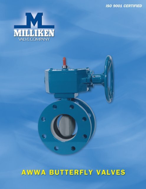
<strong>ISO</strong> <strong>9001</strong> <strong>CertIfIed</strong>
page 2<br />
3" through 20" Butterfly <strong>Valve</strong>s<br />
Scope of Line<br />
511A Flanged — 3" through 20" . . . . . . . . . . . . . . . . . . . . . . . . . . . . . . . . . .3<br />
510A Mechanical Joint — 4" through 20" . . . . . . . . . . . . . . . . . . . . . . . . . . .3<br />
Design Details . . . . . . . . . . . . . . . . . . . . . . . . . . . . . . . . . . . . . . . . . . . . . . . . . . . . .4<br />
Features and Benefits — 20" and smaller . . . . . . . . . . . . . . . . . . . . . . . . . . .5<br />
Cv Values — 20" and smaller . . . . . . . . . . . . . . . . . . . . . . . . . . . . . . . . . . . . .5<br />
Suggested Specifications — 20" and smaller . . . . . . . . . . . . . . . . . . . . . . . . .6<br />
Dimensions<br />
511A Flanged — 3" through 20" . . . . . . . . . . . . . . . . . . . . . . . . . . . . . . . . . .7<br />
510A Mechanical Joint — 4" through 20" . . . . . . . . . . . . . . . . . . . . . . . . . . .7<br />
Actuator Dimensional Data — 20" and smaller . . . . . . . . . . . . . . . . . . . . . . . . . . .8<br />
Optional Accessories . . . . . . . . . . . . . . . . . . . . . . . . . . . . . . . . . . . . . . . . . . . . . . . .8<br />
24" and Larger Butterfly <strong>Valve</strong>s<br />
Scope of Line<br />
511 Flanged — 24" through 72" . . . . . . . . . . . . . . . . . . . . . . . . . . . . . . . . . . .9<br />
510 Mechanical Joint — 24" through 48" . . . . . . . . . . . . . . . . . . . . . . . . . . .9<br />
Features and Benefits — 24" and larger . . . . . . . . . . . . . . . . . . . . . . . . . . . . . . . . .9<br />
Dimensions<br />
511 Flanged — 24" through 72" . . . . . . . . . . . . . . . . . . . . . . . . . . . . . . . . . .10<br />
510 Mechanical Joint — 24" through 48" . . . . . . . . . . . . . . . . . . . . . . . . . .10<br />
Suggested Specifications — 24" and larger . . . . . . . . . . . . . . . . . . . . . . . . . . . . .11
Scope of Line: AWWA Rubber Seated Butterfly <strong>Valve</strong>s<br />
Model 511A Butterfly <strong>Valve</strong><br />
Model 510A Mechanical Joint Butterfly <strong>Valve</strong><br />
Sizes: 4 through 20 inches<br />
Body Style: MJ x MJ ends<br />
Pressure Class:<br />
• Class 150B per AWWA Stan dard C504<br />
Working Pressure: 150 psig<br />
Model 511A Flanged Butterfly <strong>Valve</strong><br />
Sizes: 3 through 20 inches<br />
Body Style: Flanged x flanged ends<br />
Pressure Class:<br />
• Class 150B per AWWA Stan dard C504<br />
Working Pressure: 150 psig<br />
Flanges:<br />
• Flat faced and drilled in ac cor dance with ANSI B16 .1, Class 125<br />
standards .<br />
Rubber Seat: Bonded seat-in-body<br />
Rubber Seat:<br />
• Bonded seat-in-body ex tends over inner surface to form selfgasketing<br />
feature<br />
Actuation Options:<br />
• MDT manual ac tu a tor with AWWA nut<br />
Please see the outside back cover for a listing of other <strong>Milliken</strong> products<br />
Actuation Options:<br />
• MDT manual ac tu a tor with AWWA nut, handwheel or<br />
chainwheel<br />
• Hydraulic or pneumatic cylinder<br />
• Electric actuator<br />
Model 510A Butterfly <strong>Valve</strong><br />
page 3
Design Details: Models 511A and 510A — 20" and Smaller<br />
page 4<br />
Self Adjusting Permanent Packing<br />
Chevron type packing increases sealing<br />
force as line pres sure increases . The self<br />
adjusting pack ing bears on turned, ground<br />
and polished stain less steel, min i miz ing<br />
wear and assuring long life . Pack ing is<br />
ac ces si ble for re place ment with out dis mantling<br />
the valve per AWWA Stan dard C504 .<br />
Lifetime Bearings<br />
Chemically inert nylon bearings are sized<br />
to meet or exceed AWWA specification<br />
pres sure loads . They are self-lu bri cat ing,<br />
require no pe ri od ic main te nance and are<br />
de signed to outlast the life of the pipe line .<br />
Corrosion Resistant Shafts<br />
Shafts in rubber seated butterfly valves, 3”<br />
through 20”, are con struct ed of centerless,<br />
ground ASTM A276 type 304 or type 316<br />
stainless steel bar and thus are not sus cepti<br />
ble to corrosion as are carbon steel or other<br />
similar materials . Shafts are one-piece,<br />
through-shaft con struc tion, sized to meet or<br />
ex ceed the re quire ments of AWWA Standard<br />
C504 for Class 150B butterfly valves .<br />
Streamlined Discs<br />
The lens-shaped discs are designed to mini<br />
mize pres sure drop and turbulence . In<br />
the full open po si tion, the disc creates no<br />
more friction loss than a 45° el bow . Discs<br />
are secured to shafts by stain less steel pins<br />
to trans mit re quired torques and with stand<br />
stress es imposed under a va ri ety of op er ating<br />
con di tions .<br />
Body Seat<br />
Our standard seats are constructed of Buna<br />
N rub ber and bond ed to the valve body .<br />
This mold ing pro cess ensures that the discto-seat<br />
in ter fer ence will not cause ex ces sive<br />
wear or abrasion under normal op er at ing<br />
con di tions . The seat-in-body de sign mini<br />
miz es the ef fects of corrosive build up on<br />
the in side of the valve be cause deposits are<br />
swept away by the hard seal ing edge of the<br />
disc each time the valve is ex er cised .<br />
Heavy Duty Bodies<br />
Both Models 511A and 510A bodies are<br />
heavy duty cast iron . Model 511A flang es<br />
are fully faced and drilled in accordance<br />
with ANSI B16 .1, Class 125 standard for<br />
cast iron flang es . Model 510A mechanical<br />
joint end connections are in accordance<br />
with AWWA C111 and ANSI 21 .11 . The<br />
actuator mounting trun nion is ma chined<br />
and drilled for a 4-bolt connection .
Features and Benefits<br />
of <strong>Milliken</strong> Models 511A and 510A — 20" and Smaller<br />
Feature Benefit<br />
Seat-in-body design • Reduces seat failure due to corrosive buildup<br />
Seat molded in recessed body cavity, in the valve and pipeline . No hard ware to<br />
protected by metal on 3 sides loosen . No periodic maintenance required .<br />
Rubber protected from flow media to increase<br />
seat life .<br />
<strong>Valve</strong> withstood proof-of-design testing • Proven reliability over the life of the valve<br />
of 100,000 cycles - AWWA only requires<br />
10,000 cycle proof-of-design testing<br />
Through-disc pinning • Provides a tight disc-to-shaft pin connection,<br />
greatly reducing the possibility of loosening<br />
through vibration<br />
Symmetrical lens-shaped disc • Higher Cv : lower head loss results in energy<br />
savings for customer’s system<br />
Nonmetallic bearings • Prevents galvanic corrosion and provides lower<br />
coefficient of friction<br />
Chevron V-type packing • Self-adjusting, lasts the life of the valve<br />
<strong>Valve</strong><br />
Size<br />
C v<br />
<strong>Valve</strong><br />
Size<br />
C v<br />
<strong>Valve</strong><br />
Size<br />
3" 323 10" 4458 16" 11413<br />
4" 575 12" 6420 18" 14444<br />
6" 1294 14" 8738 20" 17832<br />
8" 2300 Cv values for the 511A and 510A in the full open position<br />
<strong>Valve</strong> Size Body<br />
Type of Material<br />
Disc Shaft<br />
3" - 4" Ductile Iron CF-8M Type 304SS<br />
6" Cast Iron CF-8M Type 304SS<br />
8" - 20" Cast Iron Cast Iron/316SS Edge<br />
Other materials available upon request<br />
Type 304SS<br />
C v<br />
page 5
Suggested Specification for the <strong>Milliken</strong><br />
Rubber Seated Butterfly <strong>Valve</strong>, Sizes 3 through 20 inches<br />
General<br />
Butterfly valves shall be manufactured in accordance<br />
with the latest revision of AWWA C504, Class 150B<br />
and conform to NSF Standard 61 . The manufacturer<br />
shall have produced AWWA butterfly valves for a<br />
minimum of five years . All valves shall be either 511A<br />
Flanged or 510A Mechanical Joint and comply with<br />
the following details .<br />
<strong>Valve</strong> Bodies<br />
<strong>Valve</strong> bodies shall be constructed of ASTM A126,<br />
Class B cast iron . Flanged valves shall be fully faced<br />
and drilled in accordance with ANSI Stan dard B16 .1,<br />
Class 125 . Mechanical joint end connections are in<br />
accordance with AWWA C111 and ANSI 21 .11 .<br />
<strong>Valve</strong> Seats<br />
Rubber body seats shall be of one piece construction,<br />
si mul ta neous ly mold ed and bond ed into a recessed<br />
cavity in the valve body . Seats may not be located on<br />
the disc or be retained by segments and/or screws .<br />
<strong>Valve</strong> Bearings<br />
<strong>Valve</strong> bearings shall be of a self-lubricating, nonme<br />
tal lic material to ef fec tive ly isolate the disc-shaft<br />
as sem bly from the valve body . Metal-to-metal thrust<br />
bear ings in the flow stream are not allowed .<br />
<strong>Valve</strong> Disc<br />
The disc shall be a lens-shaped design to afford mini<br />
mal pressure drop and line turbulence . Materials of<br />
construction shall be:<br />
• 3"-6" — ASTM A351 Gr. CF8M stainless steel disc<br />
• 8"-20" — ASTM A126, Class B cast iron disc with a<br />
stainless steel type 316 edge<br />
Discs shall be re tained by stain less steel pins which<br />
extends through the full diameter of the shaft to withstand<br />
the spec i fied line pres sure up to valve rating<br />
and the torque re quired to oper ate the valve . Disc<br />
stops located in the flow stream are not allowed .<br />
<strong>Valve</strong> Shafts<br />
<strong>Valve</strong> shafts shall be of stainless steel type 304 . At the<br />
op er a tor end of the valve shaft, a packing gland uti lizing<br />
“V” type chevron packing shall be utilized .<br />
page 6<br />
Painting<br />
All surfaces of the valve interior shall be clean, dry<br />
and free from grease before paint ing . The valve<br />
interior and exterior, except for disc edge, rubber<br />
seat and finished portions shall be evenly coated with<br />
a 2-part liquid epoxy to comply with NSF61 and<br />
AWWA Standard C504 .<br />
Testing<br />
Hydrostatic and seat leakage tests shall be conducted<br />
in strict accordance with AWWA Stan dard C504 .<br />
Proof of Design<br />
The manufacturer furnishing valves under the spec ifi<br />
ca tion shall be prepared to provide Proof of Design<br />
Test reports to illustrate that the valves supplied meet<br />
the design requirements of AWWA C504 .<br />
Manual Actuators: Manual actuators shall be of the<br />
trav el ing nut, self-lock ing type and shall be de signed<br />
to hold the valve in any in ter me di ate position<br />
between ful ly open and ful ly closed without creeping<br />
or flut ter ing . Ac tu a tors shall be equipped with<br />
mechanical stop-limiting devices to pre vent overtravel<br />
of the disc in the open and closed po si tions . Ac tu a tors<br />
shall be ful ly en closed and de signed to produce the<br />
spec i fied torque with a max i mum pull of 80 lb . on the<br />
handwheel or chain wheel . Actuator components shall<br />
with stand an input torque of 450 Lb . Ft . at extreme<br />
op er a tor position without dam age . Manual ac tu a tors<br />
shall conform to AWWA C504 and shall be <strong>Milliken</strong><br />
MDT or an approved equal .
Dimensional Data: Model 511A, Flanged Butterfly <strong>Valve</strong> 3" – 20"<br />
D<br />
E<br />
E<br />
— Available in sizes<br />
3 through 20 inches<br />
Nominal <strong>Valve</strong><br />
Size A B C D E F G<br />
3 43 ⁄4 37 ⁄8 71 ⁄2 5 3<br />
⁄4 4 – 5<br />
⁄8 6<br />
4 51 ⁄2 41 ⁄8 9 5 15 ⁄16 8 – 5 ⁄8 71 ⁄2<br />
6 61 ⁄2 51 ⁄8 11 5 1 8 – 3 ⁄4 91 ⁄2<br />
8 73 ⁄4 61 ⁄2 131 ⁄2 6 11 ⁄8 8 – 3 ⁄4 113 ⁄4<br />
10 9 97 ⁄8 16 8 13 ⁄16 12 – 7 ⁄8 141 ⁄4<br />
12 101 ⁄2 113 ⁄8 19 8 11 ⁄4 12 – 7 ⁄8 17<br />
14 117 ⁄8 123 ⁄4 21 8 13 ⁄8 12 – 1 183 ⁄4<br />
16 131 ⁄2 143 ⁄8 231 ⁄2 8 17 ⁄16 16 – 1 211 ⁄4<br />
18 143 ⁄8 151 ⁄4 25 8 19 ⁄16 16 – 11 ⁄8 223 ⁄4<br />
20 16 167 ⁄8 271 ⁄2 8 111 ⁄16 20 – 11 ⁄8 25<br />
All dimensions shown in inches<br />
Dimensional Data: Model 510A Mechanical Joint End<br />
Butterfly <strong>Valve</strong> — 4" – 20"<br />
PIPE<br />
I.D.<br />
Installation Diagram<br />
Note: The following items to<br />
be furnished by others unless<br />
otherwise specified in contract:<br />
Bolts, Glands, Nuts, Gaskets<br />
R<br />
F=NO. & SIZE OF BOLTS<br />
E E<br />
D A B<br />
X=<br />
LAYING LENGTH<br />
PIPE<br />
O.D.<br />
NOM.<br />
VALVE<br />
SIZE<br />
G=BOLT<br />
CIRCLE<br />
See Note 1.<br />
PIPE PIPE PIPE I.D.<br />
SIZE O.D. MIN.<br />
4 4.80 3.10<br />
6 6.90 5.69<br />
8 9.05 7.65<br />
10 11.10 9.93<br />
12 13.20 11.70<br />
14 15.30 12.91<br />
16 17.40 14.91<br />
18 19.50 16.95<br />
20 21.60 18.96<br />
— Available in sizes<br />
4 through 20 inches<br />
C<br />
Nominal <strong>Valve</strong><br />
Size A B C D E F G X<br />
4 51 ⁄2 31 ⁄2 9 81 ⁄8 1 4 – 3 ⁄4 71 ⁄2 31 ⁄8<br />
6 61 ⁄2 51 ⁄8 11 81 ⁄2<br />
11<br />
⁄16 6 – 3<br />
⁄4 91 ⁄2 31 ⁄2<br />
8 73 ⁄4 61 ⁄2 131 ⁄4 85 ⁄8 11 ⁄8 6 – 3 ⁄4 113 ⁄4 35 ⁄8<br />
10 9 93 ⁄4 159 ⁄16 91 ⁄4<br />
13<br />
⁄16 8 – 3<br />
⁄4 14 41 ⁄4<br />
12 101 ⁄2 113 ⁄8 1715 ⁄16 91 ⁄4 11 ⁄4 8 – 3 ⁄4 161 ⁄4 41 ⁄4<br />
14 117 ⁄8 123 ⁄4 205 ⁄16 111 ⁄2<br />
15<br />
⁄16 10 – 3<br />
⁄4 183 ⁄4 41 ⁄2<br />
16 131 ⁄2 141 ⁄2 229 ⁄16 12 13 ⁄8 12 – 3 ⁄4 21 5<br />
18 143 ⁄8 153 ⁄8 2411 ⁄16 121 ⁄4 13 ⁄8 12 – 3 ⁄4 231 ⁄4 51 ⁄4<br />
20 16 17 273 ⁄32 121 ⁄2 11 ⁄2 14 – 3 ⁄4 251 ⁄2 51 ⁄2<br />
All dimensions shown in inches.<br />
Mechanical joint end is in compliance with ANSI 21.11.<br />
page 7
Actuator Dimensional Data for Models 511A and 510A —<br />
20" and Smaller<br />
MDT Manual Actuator<br />
<strong>Valve</strong><br />
Size<br />
page 8<br />
J<br />
L<br />
MDT<br />
Size<br />
All di men sions<br />
shown in inches<br />
J L M N P Q R S T V W<br />
3 to 12" MDT-2 4 11 ⁄16 2 2 1 ⁄8 2 4 1 ⁄2 4 1 ⁄4 8 1 ⁄4 7 7 ⁄8 7 7 ⁄8 8 9 1 ⁄8 32<br />
14, 16" MDT-3 5 5 ⁄8 2 7 ⁄16 3 1 ⁄4 3 5 ⁄32 5 5 ⁄8 5 3 ⁄8 10 3 ⁄8 10 1 ⁄2 10 1 ⁄8 12 9 1 ⁄8 30<br />
18, 20" MDT-4 6 3 ⁄8 22 7 ⁄32 3 3 ⁄8 4 7 5 ⁄16 6 3 ⁄4 11 5 ⁄16 11 1 ⁄2 11 12 9 1 ⁄8 40<br />
Optional Accessories<br />
# Turns<br />
to Close<br />
<strong>Milliken</strong> offers a variety of actuator extensions to meet our customer’s requirements . The choice of extension<br />
style is determined by the need for valve position indication, location of the actuator and application .<br />
Extension Stem with AWWA Nut<br />
• Used to extend the 2” nut on a buried service<br />
actuator .<br />
Extension Bonnet<br />
• Used to extend the actuator from the valve in<br />
situations when there may be space constraints, or it<br />
is not desirable to mount the actuator directly on the<br />
valve .<br />
• Can be used for submerged service (such as reservoir<br />
inlet) and buried service applications .<br />
Extension Stem<br />
With 2" AWWA Nut<br />
SHOWN IN A<br />
VALVE BOX<br />
Extension<br />
EXTENSION<br />
Bonnet BONNET<br />
1"<br />
Torque tube and<br />
extension bonnet<br />
lengths to be<br />
determined by<br />
customer<br />
Support bracket<br />
when required<br />
Indicating Handwheel<br />
Floorstand<br />
FLOORSTAND<br />
UNIVERSAL<br />
JOINT<br />
CLOSED<br />
Indicating Handwheel Floorstand, Torque Tube Floorstand,<br />
Motor Actuator on Floorstand<br />
• Choice of floorstands or torque tube floorstand are determined<br />
by the need for valve position indication and angular<br />
alignment .<br />
External Packing Bonnet<br />
• There are two styles offered based on valve size . Both styles<br />
serve the same purpose; to allow for the valve packing to be<br />
replaced without removing the actuator .<br />
Stem Guide<br />
• A stem guide is a support designed to restrict the bending of a<br />
long vertical pipe .<br />
Torque Tube<br />
Floorstand<br />
TORQUE TUBE<br />
FLOORSTAND<br />
Motor Actuator<br />
Floorstand<br />
MOTOR OPERATOR<br />
ON FLOORSTAND<br />
UNIVERSAL JOINT<br />
UNIVERSAL JOINT<br />
* To be<br />
determined<br />
by customer<br />
when wall<br />
bracket is<br />
required.<br />
Steady<br />
Bearing
Features and Benefits<br />
<strong>Milliken</strong> Model 511 Flanged/<br />
510 Mechanical Joint<br />
Sizes: 24 through 72 inches<br />
Body Styles:<br />
• Flanged (24" - 72") • Mechanical Joint (24" - 48")<br />
Pressure Class:<br />
• Class 150B per AWWA Standard C504<br />
Actuation Options:<br />
• Handwheel • Buried Service<br />
• Electric Motor • Chainwheel<br />
• Pneumatic or<br />
Hydraulic Cylinder<br />
Materials of Construction:<br />
Body – ASTM A126 CLB cast iron<br />
Disc – ASTM A536 Ductile Iron<br />
Disc Edge – ASTM A276 Type 316 stainless steel<br />
Seat – Buna N/EPDM rubber retained in the body<br />
Seat Segments – ASTM A276 Type 316 stainless steel<br />
Shaft – ASTM A276 Type 304 stainless steel<br />
Bearings – Teflon lined fiberglass backed<br />
Packing – Buna N/EPDM – V type packing<br />
Paint – Liquid epoxy conforming to NSF 61 (lined and coated)<br />
Rubber seat in body • Reduces the chance of seat damage from<br />
tuberculation or other solids<br />
Recessed segmented seat retention • Allows for simple bi-directional point<br />
adjustment on rubber seat while keeping<br />
hardware out of flowstream<br />
Mechanically adjustable seat • No special tools or training required to adjust<br />
and/or replace the seat<br />
Epoxy paint • Reduces potential corrosion and extends valve<br />
life<br />
Flow though disc design • Disc design results in lower head-loss than<br />
solid or hollow disc designs<br />
page 9
page 10<br />
NOMINAL VALVE SIZE<br />
G = BOLT CIRCLE<br />
C = FLANGE OD<br />
A<br />
B<br />
D<br />
E<br />
<strong>Valve</strong><br />
Size<br />
A B C D E F G<br />
24 18 5 ⁄8 16 1 ⁄2 32 8 1 7 ⁄8 20 – 1 1 ⁄4 29 1 ⁄2<br />
30 21 1 ⁄2 24 1 ⁄8 38 3 ⁄4 12 2 1 ⁄8 28 – 1 1 ⁄4 36<br />
36 25 7 ⁄16 28 46 12 2 3 ⁄8 32 – 1 1 ⁄2 42 3 ⁄4<br />
42 29 7 ⁄8 32 11 ⁄16 53 12 2 5 ⁄8 36 – 1 1 ⁄2 49 1 ⁄2<br />
48 34 1 ⁄16 36 7 ⁄8 59 1 ⁄2 15 2 3 ⁄4 44 – 1 1 ⁄2 56<br />
54 37 1 ⁄2 40 11 ⁄16 66 1 ⁄4 15 3 44 – 1 1 ⁄2 62 3 ⁄4<br />
60 41 3 ⁄4 45 3 ⁄16 73 15 3 1 ⁄8 52 – 1 3 ⁄4 69 1 ⁄4<br />
66 46 1 ⁄16 49 1 ⁄2 80 18 3 3 ⁄8 52 – 1 3 ⁄4 76<br />
72 50 53 1 ⁄8 86 1 ⁄2 18 3 1 ⁄2 60 – 1 3 ⁄4 82 1 ⁄2<br />
*Contact <strong>Milliken</strong> for larger sizes<br />
<strong>Valve</strong><br />
Size<br />
A B C D E F G X<br />
24 18 5 ⁄8 16 1 ⁄2 31 9 ⁄16 14 1 ⁄8 1 5 ⁄8 16 3 ⁄4 30 7 1 ⁄8<br />
30 21 1 ⁄2 24 1 ⁄8 39 20 1 13 ⁄16 20 -- 1 36 7 ⁄8 10<br />
36 25 7 ⁄16 28 45 7 ⁄8 22 2 24 -- 1 43 3 ⁄4 14<br />
42 29 7 ⁄8 33 53 22 2 28 -- 1 1 ⁄4 50 5 ⁄8 14<br />
48 34 1 ⁄16 36 7 ⁄8 59 7 ⁄8 24 2 32 -- 1 1 ⁄4 57 1 ⁄2 16<br />
*Contact <strong>Milliken</strong> for larger sizes
Suggested Specification (24" and Larger)<br />
General:<br />
All butterfly valves shall be of the tight closing,<br />
rubber seat type conforming to the design standards<br />
of ANSI/AWWA C504 latest revision . <strong>Valve</strong>s shall<br />
be bubble-tight at the rated pressure in either<br />
direction and shall be suitable for throttling service<br />
and/or operation after long periods of inactivity .<br />
Manufacturer shall have a minimum of five (5) years<br />
experience producing AWWA butterfly valves .<br />
Body:<br />
All valve bodies shall be constructed of ASTM A126<br />
Class B cast iron . Flanged valves shall have ANSI<br />
B16 .1 flanges with class 125# drilling . Mechanical<br />
Joint <strong>Valve</strong>s shall have ends conforming to the<br />
ANSI/AWWA C111/A21 .11 standard .<br />
Seat:<br />
On 24” and larger valves the seat shall be adjustable<br />
and replaceable in the field without the use of<br />
special tools . <strong>Valve</strong> seats on valves 24” and larger<br />
will be designed for bi-directional adjustment<br />
without removal of the seat . <strong>Valve</strong> designs with the<br />
rubber seat on the disc are not acceptable .<br />
Disc:<br />
The discs shall be constructed of ASTM A536<br />
Ductile Iron with a 316 stainless steel edge . 24” and<br />
larger discs will be the flow through design .<br />
Shaft:<br />
The valve shaft shall be constructed of stainless steel<br />
ASTM A276 type 304 . On valves 24” and larger, a<br />
taper pin of 316 stainless steel will be used as the<br />
disc/shaft connection .<br />
Bearings:<br />
All shaft bearing shall be of the self-lubrication,<br />
corrosion-resistant sleeve type . Bearings shall be<br />
designed for horizontal and/or vertical shaft loading .<br />
Packing:<br />
On valves 24” and larger the packing will be<br />
V-type . All packing will be self adjusting and wear<br />
compensating . <strong>Valve</strong> packing arrangement shall be<br />
designed so that actuator removal will not result in<br />
packing seal failure .<br />
Paint:<br />
<strong>Valve</strong>s 24” and larger will be lined and coated with<br />
a liquid epoxy conforming to AWWA C550 and<br />
NSF61 . Coatings will be a minimum of 8 mils DFT .<br />
Testing:<br />
All valves shall be hydrostatic and leak tested in<br />
accordance with ANSI/AWWA C504 .<br />
Manual Actuators:<br />
Manual actuators shall be AWWA approved<br />
worm gear actuators . The actuator incorporates a<br />
hardened worm with bronze heavy duty quadrant<br />
within a ductile iron housing. Gear must be self<br />
locking type and shall be designed to hold the valve<br />
in any intermediate position between fully open and<br />
fully closed without creeping or fluttering . Worm<br />
gear to be rated 450 foot pounds at the stops .<br />
<strong>Valve</strong>s shall be <strong>Milliken</strong> model 511/510 or approved<br />
equivalent .<br />
page 11
Series 600/601<br />
Eccentric Plug <strong>Valve</strong><br />
Welded Nickel Seat<br />
Stainless Steel Bearings<br />
ANSI-B16 .1 Flanges<br />
Solid Ductile Iron Plug<br />
Low Pressure Drop<br />
Flanged & MJ Ends<br />
Sizes 2"-72" FL<br />
Sizes 3"-48" MJ<br />
Series 603<br />
Eccentric Plug <strong>Valve</strong><br />
Solid Ductile Iron Plug<br />
Round Port<br />
Low Pressure Drop<br />
Memory Stop<br />
NPT End Connections<br />
Sizes 1/2"-2"<br />
Model 625<br />
Eccentric Plug <strong>Valve</strong><br />
Available in Threaded<br />
and Flanged Ends<br />
Rated for 175 psi<br />
Sizes 1/2"-4"<br />
UL/CGA Listed<br />
Model 720A<br />
Wafer Check <strong>Valve</strong><br />
Center Guided<br />
Check <strong>Valve</strong><br />
Rated for 250 psi<br />
SS Disc/EPDM Seat<br />
Sizes 2"-12"<br />
Figure 565/566<br />
General Service<br />
Butterfly <strong>Valve</strong><br />
Meets MSS SP 67<br />
Cast Iron Body<br />
Bronze Disc<br />
Other Materials Upon Request<br />
Wrench or Gear<br />
Operated Available<br />
2"-24" Size Range<br />
Flanged and MJ<br />
Threaded End<br />
Bethlehem, PA<br />
Phone (610) 861-8803<br />
Fax (610) 861-8094<br />
Series 601SS<br />
Eccentric Plug <strong>Valve</strong><br />
Integral Stainless Seat<br />
Stainless Bearings<br />
Stainless Steel Body<br />
ANSI B16 .5 Class 150 Flanges<br />
Solid Stainless Steel Plug<br />
Low Pressure Drop<br />
Size: 1/2"-24"<br />
Series 604E<br />
Eccentric Plug <strong>Valve</strong><br />
Epoxy Seat<br />
Solid Ductile Iron Plug<br />
Stainless Steel Bearings<br />
Low Pressure Drop<br />
Lift & Turn NOT Required<br />
High Solids & Flow Capacity<br />
Sizes 3"-16"<br />
Series 8000<br />
AWWA Swing Check<br />
Full waterway<br />
Weight or Spring<br />
Bronze/SS Body Seat Ring<br />
Bronze/Buna/EPDM disc insert<br />
Sizes 2"-36"<br />
Series 700<br />
Wafer Check <strong>Valve</strong><br />
ANSI Class 125/150<br />
High Flow Capacity<br />
Narrow Face-to-Face<br />
Sizes 3"-12"<br />
316 SS Internals<br />
Disc Position Indicator<br />
Figure 740A<br />
Double Disc Check <strong>Valve</strong><br />
Wafer pattern<br />
check valve<br />
rated for 250 psi .<br />
Available in sizes<br />
2"-36" with a<br />
SS Disc/EPDM Seat<br />
Three Way <strong>Valve</strong><br />
Wafer Check <strong>Valve</strong><br />
Series 601RL<br />
Eccentric Plug <strong>Valve</strong><br />
Soft or Hard Rubber Lining<br />
Stainless Steel Bearings<br />
ANSI B16 .1 Flanges<br />
Solid Ductile Iron Plug<br />
Low Pressure Drop<br />
Sizes 3"-54"<br />
Metal Plugs Available<br />
– Consult Factory<br />
Series 606<br />
Eccentric Plug <strong>Valve</strong><br />
Welded Nickel Seat<br />
Stainless Steel Bearings<br />
AWWA C-606 Grooved<br />
Solid Ductile Iron Plug<br />
Low Pressure Drop<br />
Ductile or Steel Pipe<br />
Sizes 3"-24"<br />
Series 8500<br />
AWWA Swing Check<br />
Full waterway<br />
Ductile Iron Construction<br />
Weight or Spring<br />
Air Cushion<br />
SS body seat ring<br />
Buna disc insert<br />
Sizes 3"-24"<br />
Figure 851<br />
Flex Check<br />
Grooved End<br />
Million Cycle Certification<br />
Complete Ductile Iron Construction<br />
285 psi Pressure Rating<br />
Fully Epoxy Lined Interior<br />
No Internal Shafts, Bearings or Bushings<br />
No External Levers, Weights or Springs<br />
Hard or Soft<br />
Rubberlining Available<br />
2"-24" Size Range<br />
Backflush Devices<br />
Proximity Switches<br />
Figure 821A<br />
Globe Style Check <strong>Valve</strong><br />
Center guided<br />
check valve .<br />
SS Disc/EPDM Seat<br />
and is available<br />
in sizes 2"-24" .<br />
Rubber Lined<br />
Series 602<br />
Eccentric Plug <strong>Valve</strong><br />
Welded Nickel Seat<br />
Stainless Steel Bearings<br />
ANSI B16 .1 Class 250 Flanges<br />
Solid Ductile Iron Plug<br />
Low Pressure Drop<br />
Sizes 2-1/2"-54"<br />
Series 611/610<br />
Eccentric Plug <strong>Valve</strong><br />
Ductile Iron Body<br />
ANSI B16 .1 Flanges<br />
MJ AWWA C111<br />
Welded Nickel Seat<br />
Solid Ductile Iron Plug<br />
Low Pressure Drop<br />
Sizes 2"-72" FL<br />
Sizes 3"-48" MJ<br />
Series 9000<br />
AWWA Swing Check<br />
Clear waterway<br />
Weight or Spring<br />
Air or Oil Cushion<br />
Bronze/SS Body seat ring<br />
Bronze/Buna/EPDM disc insert<br />
Sizes 3"-72"<br />
Figure 510A/511A<br />
AWWA Butterfly <strong>Valve</strong><br />
Complies with AWWA C-504<br />
Class 150B Flanged or MJ<br />
Cast iron body and disc<br />
Seat in body<br />
Flow through disc on<br />
24" and larger<br />
Epoxy Paint on all sizes<br />
standard<br />
3" - 72"<br />
High Pressure<br />
Flanged and MJ<br />
• <strong>ISO</strong> <strong>9001</strong>:2000<br />
Certified<br />
• Field Services<br />
Available<br />
• Engineering<br />
Services<br />
MBFV-01-12