Failure Analysis and Defect Review for the 45 nm ... - Carl Zeiss SMT
Failure Analysis and Defect Review for the 45 nm ... - Carl Zeiss SMT
Failure Analysis and Defect Review for the 45 nm ... - Carl Zeiss SMT

You also want an ePaper? Increase the reach of your titles
YUMPU automatically turns print PDFs into web optimized ePapers that Google loves.
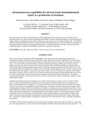
<strong>Failure</strong> <strong>Analysis</strong> <strong>and</strong> <strong>Defect</strong> <strong>Review</strong> <strong>for</strong> <strong>the</strong> <strong>45</strong> <strong>nm</strong> Node Using Extended Accuracy of <strong>the</strong>...<br />
SECOND QUARTER 2005 www.sme.org/ama VOL. 20, NO. 2<br />
<strong>Failure</strong> <strong>Analysis</strong> <strong>and</strong> <strong>Defect</strong> <strong>Review</strong> <strong>for</strong> <strong>the</strong><br />
<strong>45</strong> <strong>nm</strong> Node Using Extended Accuracy<br />
of <strong>the</strong> CrossBeam Technology<br />
Peter Gnauck, PhD, <strong>Carl</strong> <strong>Zeiss</strong> NTS GmbH (Oberkochen, Germany) <strong>and</strong><br />
Christian Boit, PhD, Berlin University of Technology (Berlin, Germany)<br />
As we look <strong>for</strong>ward to <strong>the</strong> 65 <strong>nm</strong> <strong>and</strong> <strong>45</strong> <strong>nm</strong> technology nodes, challenges<br />
arise in virtually every aspect of <strong>the</strong> semiconductor industry. The push to<br />
smaller dimensions puts dem<strong>and</strong>s on lithography <strong>and</strong> mask making, as well<br />
as etching processes. The push <strong>for</strong> new materials to increased frequencies<br />
creates challenges with deposition, patterning, integration <strong>and</strong> inspection, as<br />
well as packaging. Fab automation continues to be important, not only in<br />
terms of optimizing yield <strong>and</strong> fab efficiency, but also in terms of supply chain<br />
management. Equipment <strong>and</strong> materials suppliers, <strong>and</strong> <strong>the</strong>ir own suppliers of<br />
components <strong>and</strong> subsystems, are developing tools to meet <strong>the</strong>se challenges.<br />
Without a doubt, process control is a major metrology obstacle facing those<br />
considering technology requirements <strong>for</strong> work at <strong>the</strong> <strong>45</strong> <strong>nm</strong> node. One of <strong>the</strong><br />
most important means of controlling that process is precision. When design<br />
engineers contemplate work in dimensions below 50 <strong>nm</strong>, <strong>the</strong>y must deal with<br />
tolerances in <strong>the</strong> range of ~5 <strong>nm</strong>.<br />
These requirements put a high dem<strong>and</strong> on <strong>the</strong> inspection tools with regard to<br />
accuracy <strong>and</strong> resolution. The resolution of single-beam focused ion beam<br />
(FIB) instruments [1] is not sufficient anymore to deal with <strong>the</strong> necessary<br />
accuracy. To overcome this problem, <strong>the</strong> FIB tool must be combined with a<br />
high-resolution SEM that is used to monitor <strong>the</strong> FIB work on a nanometer<br />
scale. These integrated CrossBeam ® tools enable <strong>the</strong> observation <strong>and</strong> direct<br />
control of <strong>the</strong> FIB operation in real time. In addition to <strong>the</strong> improved accuracy<br />
<strong>and</strong> resolution, <strong>the</strong> electron beam adds analytical capabilities, such as STEM,<br />
EDS <strong>and</strong> EBSP, to <strong>the</strong> instruments.<br />
System Layout<br />
The CrossBeam tools combine <strong>the</strong> imaging <strong>and</strong> analytical capabilities of a<br />
high-resolution field emission SEM (FESEM) with a high-per<strong>for</strong>mance FIB<br />
column into one integrated instrument (Figure 1). In <strong>the</strong> case of <strong>the</strong><br />
CrossBeam tool, <strong>the</strong> final lens of <strong>the</strong> FESEM is designed as a<br />
magnetic/electrostatic compound lens. This layout has <strong>the</strong> advantage of no<br />
magnetic field interfering with <strong>the</strong> ion beam, <strong>and</strong> <strong>the</strong> FESEM can be operated<br />
at nanometer resolution during <strong>the</strong> ion milling process. This layout allows full<br />
control over <strong>the</strong> total process <strong>and</strong> gives an excellent endpoint detection <strong>and</strong><br />
cut localization <strong>for</strong> defect review <strong>and</strong> failure analysis.<br />
file://W:\Pub\MemPub\helkdia\em\2q05em01.html<br />
Page 1 of 6<br />
4/26/2005
<strong>Failure</strong> <strong>Analysis</strong> <strong>and</strong> <strong>Defect</strong> <strong>Review</strong> <strong>for</strong> <strong>the</strong> <strong>45</strong> <strong>nm</strong> Node Using Extended Accuracy of <strong>the</strong>...<br />
Figure 1. Schematic layout of <strong>Zeiss</strong> CrossBeam tool. The electron<br />
<strong>and</strong> ion beam coincide at 5 mm below <strong>the</strong> final lens of FESEM.<br />
Toge<strong>the</strong>r with a multichannel gas injection system <strong>for</strong> metal <strong>and</strong> insulator<br />
deposition <strong>and</strong> <strong>for</strong> enhanced <strong>and</strong> selective etching, <strong>the</strong> CrossBeam<br />
workstation is a very powerful analytical <strong>and</strong> imaging tool <strong>for</strong> a wide range of<br />
applications within <strong>the</strong> semiconductor industry.<br />
SEM Cross Sections<br />
Cross sectioning in a st<strong>and</strong>ard FIB workstation is basically a blind process.<br />
The sample surface is imaged with <strong>the</strong> FIB be<strong>for</strong>e cutting to determine <strong>the</strong><br />
area of interest. Afterward, <strong>the</strong> sample is milled <strong>and</strong> polished with a<br />
predefined milling pattern. Without <strong>the</strong> possibility of monitoring <strong>the</strong> milling<br />
process directly, <strong>the</strong> area of interest can easily be destroyed.<br />
The unique capability of <strong>the</strong> CrossBeam tools to image <strong>the</strong> sample in real<br />
time at high resolution during <strong>the</strong> ion milling process gives <strong>the</strong> operator a<br />
direct interactive control to <strong>the</strong> ion milling process (Figure 2). This results in<br />
an extended accuracy on site-specific cross sections. The milling <strong>and</strong><br />
polishing process can be directly imaged <strong>and</strong> stopped exactly at <strong>the</strong> detail of<br />
interest (Figure 3). Especially in <strong>the</strong> case of TEM sample preparation, <strong>the</strong><br />
danger of destroying <strong>the</strong> fine lamella is reduced to a minimum.<br />
file://W:\Pub\MemPub\helkdia\em\2q05em01.html<br />
Page 2 of 6<br />
4/26/2005
<strong>Failure</strong> <strong>Analysis</strong> <strong>and</strong> <strong>Defect</strong> <strong>Review</strong> <strong>for</strong> <strong>the</strong> <strong>45</strong> <strong>nm</strong> Node Using Extended Accuracy of <strong>the</strong>...<br />
Figure 2. Three-dimensional analysis of a semiconductor device.<br />
The image was taken during ion milling.<br />
Figure 3. Cross section through tungsten plugs in a semiconductor device.<br />
The image was taken during ion milling. The milling process<br />
can be stopped exactly in <strong>the</strong> center of <strong>the</strong> plugs.<br />
Ano<strong>the</strong>r advantage of <strong>the</strong> CrossBeam technology is <strong>the</strong> time-saving cut-<strong>and</strong>see<br />
operation—<strong>the</strong> sample is imaged during or immediately after <strong>the</strong><br />
polishing. This results in extremely short inspection times <strong>for</strong> each cross<br />
section. In addition, digital video, recorded during <strong>the</strong> cutting process, can be<br />
used <strong>for</strong> three-dimensional reconstruction of <strong>the</strong> sample.<br />
TEM Sample Preparation<br />
Several TEM sample preparation techniques using FIB, such as prethinning<br />
(Figure 4) <strong>and</strong> lift-out techniques (Figures 5 <strong>and</strong> 6) have been published [2-4].<br />
The FIB lift-out technique allows thin membranes to be extracted from bulk<br />
material, which saves a lot of sample prethinning time <strong>and</strong> is very successful<br />
in <strong>the</strong> preparation of site-specific cross sections <strong>and</strong> planar samples.<br />
Although TEM sample preparation can be automated by using scripts <strong>and</strong><br />
macros, <strong>the</strong> best accuracy is achieved if <strong>the</strong> milling is done manually with<br />
direct SEM observation. (Keep in mind that an automated process is a blind<br />
process.) In a first step, <strong>the</strong> sample is milled <strong>and</strong> polished from <strong>the</strong> front side<br />
under continuous SEM control until <strong>the</strong> detail of interest is visible. In <strong>the</strong><br />
second step, <strong>the</strong> sample is rotated by 180°, <strong>and</strong> <strong>the</strong> backside of <strong>the</strong> sample is<br />
milled <strong>and</strong> polished under continuous SEM control until <strong>the</strong> desired thickness<br />
is achieved (Figure 4).<br />
file://W:\Pub\MemPub\helkdia\em\2q05em01.html<br />
Page 3 of 6<br />
4/26/2005
<strong>Failure</strong> <strong>Analysis</strong> <strong>and</strong> <strong>Defect</strong> <strong>Review</strong> <strong>for</strong> <strong>the</strong> <strong>45</strong> <strong>nm</strong> Node Using Extended Accuracy of <strong>the</strong>...<br />
Figure 4. Steps <strong>for</strong> prethinned TEM sample preparation<br />
using CrossBeam technology.<br />
Figure 5. TEM lift-out sample preparation using CrossBeam technology. After<br />
<strong>the</strong> final polish, <strong>the</strong> lamella is cut out of <strong>the</strong> substrate by three cuts <strong>and</strong> is<br />
transferred to a TEM grid by use of a micromanipulator <strong>and</strong> a glass needle.<br />
Figure 6. TEM lift-out sample after milling <strong>and</strong> polishing.<br />
The sample is cut out of <strong>the</strong> substrate <strong>and</strong> is ready <strong>for</strong> lift-out.<br />
Note <strong>the</strong> electron transparency of <strong>the</strong> thin area.<br />
By imaging <strong>the</strong> TEM sample in <strong>the</strong> SEM, <strong>the</strong> danger of destroying <strong>the</strong> TEM<br />
lamella due to drift <strong>and</strong> so on is minimized. Ano<strong>the</strong>r opportunity of <strong>the</strong> direct<br />
file://W:\Pub\MemPub\helkdia\em\2q05em01.html<br />
Page 4 of 6<br />
4/26/2005
<strong>Failure</strong> <strong>Analysis</strong> <strong>and</strong> <strong>Defect</strong> <strong>Review</strong> <strong>for</strong> <strong>the</strong> <strong>45</strong> <strong>nm</strong> Node Using Extended Accuracy of <strong>the</strong>...<br />
SEM imaging is a very straight control of <strong>the</strong> specimen thickness <strong>and</strong> electron<br />
transparency during <strong>the</strong> ion milling process (Figure 7).<br />
Figure 7. TEM sample during ion milling. The lamella can be positioned<br />
exactly at <strong>the</strong> area of interest. Note <strong>the</strong> electron transparency of <strong>the</strong> thin area.<br />
The best result concerning time <strong>and</strong> accuracy is achieved if different samples<br />
are prethinned automatically overnight to a thickness of about 1 µm <strong>and</strong> <strong>the</strong>n<br />
polished manually under high-resolution SEM observation.<br />
STEM Imaging<br />
By inserting a multimode STEM detector into <strong>the</strong> instrument, analysis on a<br />
subnanometer level is possible. Toge<strong>the</strong>r with <strong>the</strong> real-time imaging<br />
capabilities, extremely accurate <strong>and</strong> site-specific cross sections can be<br />
per<strong>for</strong>med <strong>and</strong> analyzed at a sub <strong>nm</strong> level. Figure 8 shows an example of a<br />
sub-µm defect in a semiconductor sample that could be located by using <strong>the</strong><br />
live imaging possibilities of <strong>the</strong> CrossBeam. The image was taken using <strong>the</strong><br />
STEM mode of <strong>the</strong> CrossBeam system.<br />
Figure 8. 30 kV bright field STEM image of a semiconductor structure.<br />
A very small defect was hit exactly in <strong>the</strong> center.<br />
file://W:\Pub\MemPub\helkdia\em\2q05em01.html<br />
Page 5 of 6<br />
4/26/2005
<strong>Failure</strong> <strong>Analysis</strong> <strong>and</strong> <strong>Defect</strong> <strong>Review</strong> <strong>for</strong> <strong>the</strong> <strong>45</strong> <strong>nm</strong> Node Using Extended Accuracy of <strong>the</strong>...<br />
References<br />
[1] Orloff, J. "High-Resolution Focused Ion Beams." <strong>Review</strong> of Scientific<br />
Instruments (v64, n5, May 1993), pp1105-1130.<br />
[2] Herlinger, L.R.; Chevacharoenkul, S.; <strong>and</strong> Erwin, D.C. "TEM Sample<br />
Preparation Using a Focused Ion Beam <strong>and</strong> a Probe Manipulator." Proc.<br />
of 22nd Int'l Symp. <strong>for</strong> Testing <strong>and</strong> <strong>Failure</strong> <strong>Analysis</strong>, Materials Park, Ohio:<br />
ASM Int'l, 1996, pp199-205.<br />
[3] Rai, R.; Subramanian, S.; Rose, S.; Conner, J.; <strong>and</strong> Schani, P.; <strong>and</strong><br />
Moss, J. "Specific Area Planar <strong>and</strong> Cross-Sectional Lift-Out Techniques:<br />
Procedures <strong>and</strong> Novel Applications." Proc. of 26th Int'l Symp. <strong>for</strong> Testing<br />
<strong>and</strong> <strong>Failure</strong> <strong>Analysis</strong>, ASM Int'l, Nov. 12-15, 2000, Bellevue, Wash.,<br />
p415-421.<br />
[4] Shofner, T.L.; Drown, J.L.; Brown, S.R.; Rossie, B.B.; Decker, M.A.;<br />
Obeng, Y.S.; <strong>and</strong> Stevie, F.A. "Planar TEM <strong>Analysis</strong> of Nanoindented<br />
Samples Using <strong>the</strong> Focused Ion Beam Lift-out Technique." Proc. of 26th<br />
Int'l Symp. <strong>for</strong> Testing <strong>and</strong> <strong>Failure</strong> <strong>Analysis</strong>, ASM Int'l, Nov. 12-15, 2000,<br />
Bellevue, Wash., p<strong>45</strong>9-461.<br />
file://W:\Pub\MemPub\helkdia\em\2q05em01.html<br />
Page 6 of 6<br />
4/26/2005