Inspiring experiments exploit strong attraction of magnets
Inspiring experiments exploit strong attraction of magnets
Inspiring experiments exploit strong attraction of magnets

You also want an ePaper? Increase the reach of your titles
YUMPU automatically turns print PDFs into web optimized ePapers that Google loves.
F RONTLINE<br />
M AGNETISM<br />
<<strong>strong</strong>>Inspiring</<strong>strong</strong>> <<strong>strong</strong>>experiments</<strong>strong</strong>> <<strong>strong</strong>>exploit</<strong>strong</strong>><br />
<strong>strong</strong> <strong>attraction</strong> <strong>of</strong> <strong>magnets</strong><br />
The extra strength <strong>of</strong> neodymium iron boron <strong>magnets</strong><br />
provides opportunities for several <<strong>strong</strong>>experiments</<strong>strong</strong>><br />
(Featonby 2005). Here is a further selection that<br />
should encourage you to think <strong>of</strong> even more.<br />
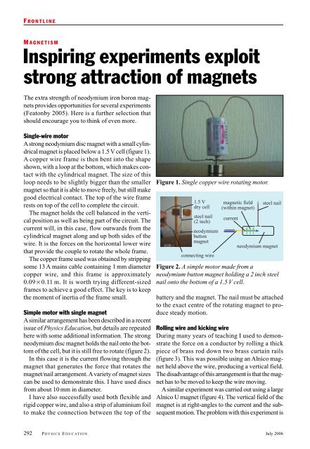
Single-wire motor<br />
A<strong>strong</strong> neodymium disc magnet with a small cylindrical<br />
magnet is placed below a 1.5 V cell (figure 1).<br />
A copper wire frame is then bent into the shape<br />
shown, with a loop at the bottom, which makes contact<br />
with the cylindrical magnet. The size <strong>of</strong> this<br />
loop needs to be slightly bigger than the smaller<br />
magnet so that it is able to move freely, but still make<br />
good electrical contact. The top <strong>of</strong> the wire frame<br />
rests on top <strong>of</strong> the cell to complete the circuit.<br />
The magnet holds the cell balanced in the vertical<br />
position as well as being part <strong>of</strong> the circuit. The<br />
current will, in this case, flow outwards from the<br />
cylindrical magnet along and up both sides <strong>of</strong> the<br />
wire. It is the forces on the horizontal lower wire<br />
that provide the couple to rotate the whole frame.<br />
The copper frame used was obtained by stripping<br />
some 13 A mains cable containing 1 mm diameter<br />
copper wire, and this frame is approximately<br />
0.09 × 0.11 m. It is worth trying different-sized<br />
frames to achieve a good effect. The key is to keep<br />
the moment <strong>of</strong> inertia <strong>of</strong> the frame small.<br />
Simple motor with single magnet<br />
Asimilar arrangement has been described in a recent<br />
issue <strong>of</strong> Physics Education, but details are repeated<br />
here with some additional information. The <strong>strong</strong><br />
neodymium disc magnet holds the nail onto the bottom<br />
<strong>of</strong> the cell, but it is still free to rotate (figure 2).<br />
In this case it is the current flowing through the<br />
magnet that generates the force that rotates the<br />
magnet/nail arrangement. Avariety <strong>of</strong> magnet sizes<br />
can be used to demonstrate this. I have used discs<br />
from about 10 mm in diameter.<br />
I have also successfully used both flexible and<br />
rigid copper wire, and also a strip <strong>of</strong> aluminium foil<br />
to make the connection between the top <strong>of</strong> the<br />
Figure 1. Single copper wire rotating motor.<br />
1.5 V<br />
dry cell<br />
steel nail<br />
(2 inch)<br />
neodymium<br />
button<br />
magnet<br />
connecting wire<br />
magnetic field<br />
(within magnet)<br />
current<br />
steel nail<br />
neodymium magnet<br />
Figure 2. A simple motor made from a<br />
neodymium button magnet holding a 2 inch steel<br />
nail onto the bottom <strong>of</strong> a 1.5 V cell.<br />
battery and the magnet. The nail must be attached<br />
to the exact centre <strong>of</strong> the rotating magnet to produce<br />
steady motion.<br />
Rolling wire and kicking wire<br />
During many years <strong>of</strong> teaching I used to demonstrate<br />
the force on a conductor by rolling a thick<br />
piece <strong>of</strong> brass rod down two brass curtain rails<br />
(figure 3). This was possible using an Alnico magnet<br />
held above the wire, producing a vertical field.<br />
The disadvantage <strong>of</strong> this arrangement is that the magnet<br />
has to be moved to keep the wire moving.<br />
Asimilar experiment was carried out using a large<br />
Alnico U magnet (figure 4). The vertical field <strong>of</strong> the<br />
magnet is at right-angles to the current and the subsequent<br />
motion. The problem with this experiment is<br />
292 P HYSICS E DUCATION July 2006
Figures 3 and 4. The rolling wire (top image): a<br />
demonstration <strong>of</strong> the force on a conductor<br />
achieved by rolling a thick piece <strong>of</strong> brass rod along<br />
a pair <strong>of</strong> brass curtain rails using an Alnico<br />
magnet held above the wire to produce a vertical<br />
field. The kicking wire (bottom): a large Alnico U<br />
magnet is used to produce a vertical field at rightangles<br />
to the current and to the subsequent motion.<br />
the expense <strong>of</strong> the large Alnico magnet, but a similar<br />
effect can be obtained with magnadur <strong>magnets</strong>.<br />
With neodymium iron boron <strong>magnets</strong> a kicking<br />
wire can be set up for less than £5 by mounting<br />
a single round neodymium magnet in a hole in a<br />
block <strong>of</strong> wood and using a trapeze-style copper<br />
frame (figure 5).<br />
Double magnet roller<br />
We can use neodymium disc <strong>magnets</strong> as both the<br />
wheels <strong>of</strong> a roller and the source <strong>of</strong> the magnetic<br />
field. In this set-up (figure 6) two discs are placed<br />
carefully on the smoothed, flat end <strong>of</strong> a nail with its<br />
head cut <strong>of</strong>f. It is important that the nail axle is<br />
aligned exactly with the centres <strong>of</strong> the <strong>magnets</strong> to<br />
produce a good run. The strength <strong>of</strong> the neodymi-<br />
July 2006<br />
F RONTLINE<br />
Figure 5. Kicking wire set-up using a neodymium<br />
magnet and a copper wire trapeze frame. The<br />
wire carries the current across the top <strong>of</strong> the<br />
magnet and the force causes the frame to move.<br />
nail shaft<br />
aluminium foil<br />
neodymium magnet<br />
magnetic field<br />
inside magnet<br />
current<br />
Figure 6. Rolling motor (shaft <strong>of</strong> nail) with two<br />
neodymium disc <strong>magnets</strong>, with explanation.<br />
ums enables them to be fixed with like poles facing<br />
each other. This is essential to produce a turning<br />
force on both wheels in the same sense. The tracks<br />
are two strips <strong>of</strong> aluminium foil, stuck to the bench<br />
with overhanging ends for electrical contacts. The<br />
current flows down the aluminium and up through<br />
one magnet, along the nail and down through the<br />
P HYSICS E DUCATION 293
F RONTLINE<br />
Figure 7. Another simple motor that uses a<br />
neodymium magnet with a bolt through its centre.<br />
Figure 9. ‘Loudspeaker’with cardboard box.<br />
other. The forces arise within the magnetic wheels<br />
and the arrangement accelerates down the track.<br />
Other motors<br />
In figure 7 a ring magnet has a bolt through its centre<br />
and lies on a copper circuit board. The magnet makes<br />
contact outside a circle etched in the board and a pin<br />
though the centre enables contact to be made there.<br />
In figure 8 a strip <strong>of</strong> aluminium foil rotates rapidly<br />
on top <strong>of</strong> the <strong>magnets</strong>. Contact is made to the<br />
central part <strong>of</strong> the rotating foil with some pencil lead,<br />
while the foil touches the outside <strong>of</strong> the <strong>magnets</strong>.<br />
Loudspeaker<br />
The strength <strong>of</strong> the neodymium magnet can be<br />
shown with a simple ‘loudspeaker’(figure 9). Acoil<br />
<strong>of</strong> thin copper wire is taped to the surface <strong>of</strong> a shoe<br />
box with the leads connected to the earphone output<br />
<strong>of</strong> a portable hi-fi. Simply bring up a neodymium<br />
magnet and the forces on the coil move it to produce<br />
sound from the box. Varying the position <strong>of</strong><br />
the magnet and hence the strength <strong>of</strong> the field at the<br />
coil greatly affects the volume <strong>of</strong> the sound.<br />
Figure 8. A motor arrangement using a piece <strong>of</strong><br />
aluminium foil rotating rapidly on top <strong>of</strong> <strong>magnets</strong>.<br />
Figure 10. A simple<br />
but effective loudspeaker<br />
unit that uses<br />
a piece <strong>of</strong> aluminium<br />
foil over a large<br />
neodymium magnet<br />
and passes the<br />
output from a radio<br />
through the<br />
aluminium foil layer.<br />
Even simpler is to lay a small piece <strong>of</strong> aluminium<br />
foil over a large neodymium magnet and pass the<br />
output from a radio through the foil (figure 10). The<br />
sound from the radio is clearly heard. This set-up<br />
can also be used as a simple microphone.<br />
You may by now be thinking that neodymium <strong>magnets</strong><br />
are the best thing since sliced bread, but with<br />
their strength come disadvantages. Neodymium iron<br />
boron is susceptible to corrosion if unprotected,<br />
though this will not be <strong>of</strong> great concern to us because<br />
commercially available <strong>magnets</strong> are coated.<br />
Curie temperature<br />
Of more concern is the Curie temperature. At only<br />
120 ºC neodymium <strong>magnets</strong> cease to be magnetic,<br />
although this loss can be recovered by remagnetization.<br />
The comparable temperature for ferrite<br />
<strong>magnets</strong> is 250 ºC and for Alnico it is 550 ºC. The<br />
loss in magnetism in neodymium is irreversible at<br />
320 ºC compared with 860 ºC for Alnico.<br />
This low Curie temperature for neodymium can<br />
be demonstrated simply by using a tealight candle<br />
as a heat source (figure 11). A small neodymium<br />
294 P HYSICS E DUCATION July 2006
Figure 11. Demonstration <strong>of</strong> the Curie temperature.<br />
ring magnet is suspended on a swing cradle made<br />
<strong>of</strong> thick copper wire, which is in turn suspended on<br />
a frame <strong>of</strong> the same copper wire. This small magnet<br />
is attracted to a larger, fixed neodymium magnet<br />
(25 × 5 mm). When the candle is lit, it heats up<br />
the small magnet, which then loses its magnetism<br />
and falls back with the swing in the vertical position.<br />
This, however, takes it out <strong>of</strong> the flame and<br />
enables it to cool, be remagnetized and attracted<br />
once more to the larger magnet. Here it is again in<br />
the flame, so it heats and loses its magnetism again,<br />
F RONTLINE<br />
and the cycle repeats. The overall size <strong>of</strong> my demonstration<br />
can be seen from the size <strong>of</strong> the tealight<br />
used. Considerable testing is required to produce a<br />
reliable demonstration.<br />
Safety warning<br />
Neodymium <strong>magnets</strong> are dangerous because <strong>of</strong> their<br />
strength and the fact that they shatter easily. They<br />
should not be given to children to use unsupervised.They<br />
should be kept away from electronic<br />
apparatus and the magnetic strips on bank cards.<br />
References<br />
Featonby D 2005 Phys. Educ. 40 505–8<br />
Neodymium <strong>magnets</strong> are available from<br />
www.power<strong>magnets</strong>tore.co.uk<br />
www.sci-toys.com/scitoys/electro has<br />
instructions about how to construct a number <strong>of</strong><br />
<<strong>strong</strong>>experiments</<strong>strong</strong>> using neodymium <strong>magnets</strong><br />
www.wondermagnet.com also has some<br />
interesting <<strong>strong</strong>>experiments</<strong>strong</strong>><br />
www.amasci.com/neodemo.html includes some<br />
neodymium demonstrations<br />
David Featonby, North East Teacher Network<br />
coordinator.