OP-769 16" Three Gun Turrets Part 2 - Personal Page of GENE ...
OP-769 16" Three Gun Turrets Part 2 - Personal Page of GENE ...
OP-769 16" Three Gun Turrets Part 2 - Personal Page of GENE ...

Create successful ePaper yourself
Turn your PDF publications into a flip-book with our unique Google optimized e-Paper software.
<strong>OP</strong> <strong>769</strong> 16 INCH THREE GU N TURRETS<br />
and 16.5 feet above the axes <strong>of</strong> the r ollers <strong>of</strong> the r olle<br />
r path. Turret structural supports for the lugs are<br />
spaced to locate the s lides and their guns as follows:<br />
The axis <strong>of</strong> the center gun bore is on the turret cent<br />
erline. The axes <strong>of</strong> the right and left gun bores are<br />
parallel to that <strong>of</strong> the center gun and are each spaced<br />
122 inches from it.<br />
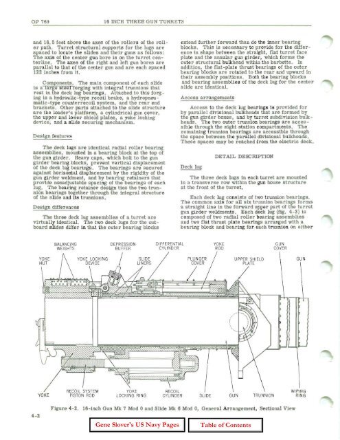
Components. The main component <strong>of</strong> each s lide<br />
is a large steel for ging with integral trunnions that<br />
rest in the deck lug bearings. Attached to this forging<br />
is a hydraulic-type r ecoil brake, a hydropneu <br />
matic -type counterrecoil system, and the r ear end<br />
brackets. other parts attached to the s lide structure<br />
are the loader's platform, a cylindrical gun cover,<br />
the upper and lower shield plates 1 a yoke locking<br />
device, and a slide securing mecnanism.<br />
Design features<br />
The deck lugs are identical radial roller bearing<br />
assemblies, mounted in a bearing block at the top <strong>of</strong><br />
the gun girder. Heavy caps, which bolt to the gun<br />
girder bearing blocks, prevent vertical displacement<br />
<strong>of</strong> the deck lug bearings. The bearings are secured<br />
against hor izontal displacement by the rigidity <strong>of</strong> the<br />
gun girder weldment, and by bea ring r etainers that<br />
provide nonadjustable spacing <strong>of</strong> the bearings <strong>of</strong> each<br />
lug. The bearing r etainer design ties the two trunnion<br />
bearings together through the integral structure<br />
<strong>of</strong> the s lide and its t runnions.<br />
Design differences<br />
The three deck lug ass emblies <strong>of</strong> a turret are<br />
virtually identical. The two deck lugs for the out <br />
board slides differ in that the outer bearing blocks<br />
4-2<br />
YOK E<br />
BALANCING<br />
WEIGHTS<br />
DEPRESSION<br />
BU FFER<br />
DIFFERENTIAL<br />
CY LIND ER<br />
extend further forward than do the inner bearing<br />
blocks. This is necess ary to provide for the difference<br />
in shape between the str aight , flat turret face<br />
plate and the arulUlar gun girder , which forms the<br />
outer structural bulkhead within the barbette. In<br />
addition, the flat-plate thrust bearings <strong>of</strong> the outer<br />
bearing blocks are r otated to the r ear and upward in<br />
their ass embly pOSitions. Both the bearing blocks<br />
and bearing assemblies <strong>of</strong> the deck lug for the center<br />
slide are identical.<br />
Access arrangements<br />
Access to the deck lug bearings 1s provided for<br />
by parallel divisional bulkheads that are formed by<br />
the gun girder boxes, and by tur r et subdivision bulkheads.<br />
The two outer trunnion bearings are accessible<br />
through the sight st ation compartments . The<br />
remaining t runnion bearings are accessible through<br />
the space between the parallel divisional bulkheads .<br />
These spaces may be reached fr om the electric deck.<br />
Deck lug<br />
DETAIL DESCRIPTION<br />
The thr ee deck lugs in each tur ret are mounted<br />
in a transverse row within the gun house structure<br />
at the front <strong>of</strong> the turret.<br />
Each deck lug consists <strong>of</strong> two trunnion bearings.<br />
The common axis for all six t runnion bearings forms<br />
a straight line in the forward upper part <strong>of</strong> the turret<br />
gun girder weldments. Each deck lug (fig. 4-3) is<br />
composed <strong>of</strong> two radial r oller bear ing assemblies<br />
and two flat thr ust plate bearings ar ranged with a<br />
bearing block and bear ing for each trunnion on either<br />
SLIDE<br />
YOKE<br />
ROD<br />
UPPER SH I ELD<br />
PLATE<br />
GUN TRUNNI ON<br />
GUN<br />
COVER<br />
Figure 4-2. 16 -inch <strong>Gun</strong> :MIt 7 Mod 0 and Slide :MIt 6 Mod 0, General Arr angement, Sectional View<br />
GUN<br />
WIPI NG<br />
RING